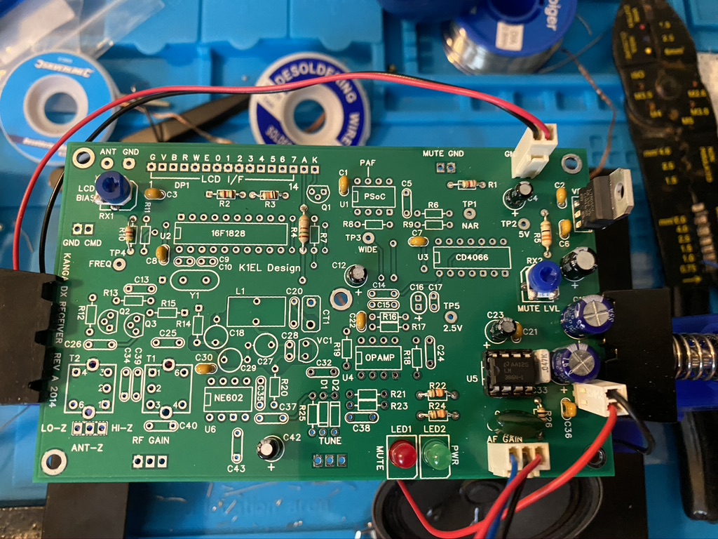
The next stage in the kit was to complte the Variable-frequency oscillator (VFO) & VFO Buffering. The first part of this is quiet detailed and delicate, and wanted to do it seperate from the regular resistor and capactiors stages. The instructions do say to add the Toroid towards the end of mounting but given its positon on the center of the board, it wont get in the way from what I can see.
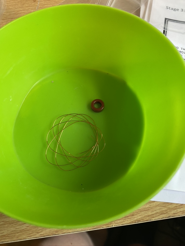
I done my usual task of seperateing the parts out in the small bowl I have, even tho there are only two parts at this stage, the magent and the 28SWG copper wire.
Firstly i straightend the wire out to remove any kinks, and using a combination of tweezers and my hand started to thread the wire thru. I kept 10mm (maybe +/- 2~3mm) as the winding start. After 10 winds, and still keeping a tight hold of the magnet and wire, not knowing how it would ‘behave’ i took a look at how it was ‘forming’ on the magnet. So far so good, so kept winding. I found that towards the end it was getting quiet tight, but not difficult, sliding the wire up and around the magnet gave me the space I needed.
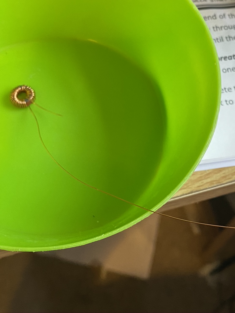
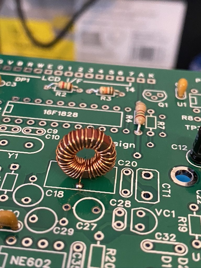
the wound toroid
I felt having none done this before, it hadn’t turned out too bad, there was one little kink in the wire, but in 33 turns, thought that was an ok ratio for a newbie toroid winder like me !
I then set about how to mount the toroid on the PCB. I used a reference picture of how other people (or person) had mounted it. The next step was to cut then tin, so i trimmed the wire back to a length that would help with mounting ahead of tinning.
For tinning to work, i turned my soldering station upto its max power of 450c which created the desired ‘bead’ of solder and melted thru the coating on the wire, leaving a nicely tinned wire to solder to.
‘top side’ soldering
My soldering workstation is great in being able to ‘flip’ so i can easily solder components when pushed thru form the top. The Toroid presented a channege as there was no real way to exert any ‘force’ and flip the board over, nor did I really want to try the method of putting a small blob on one hole then to heat and push thru, as I thought the pressure would disfigure the winding. I’ve not used this ‘technique’ before, but I decided to use a ‘holding’ weld solder spot from the top on both sides. Indeed, rather than even move the board from the holder, I roated the entire board 360 so I could top-solder the other side in. From what I could see, this has worked very well with a secure toroid and good spaceing between the start and the finish.
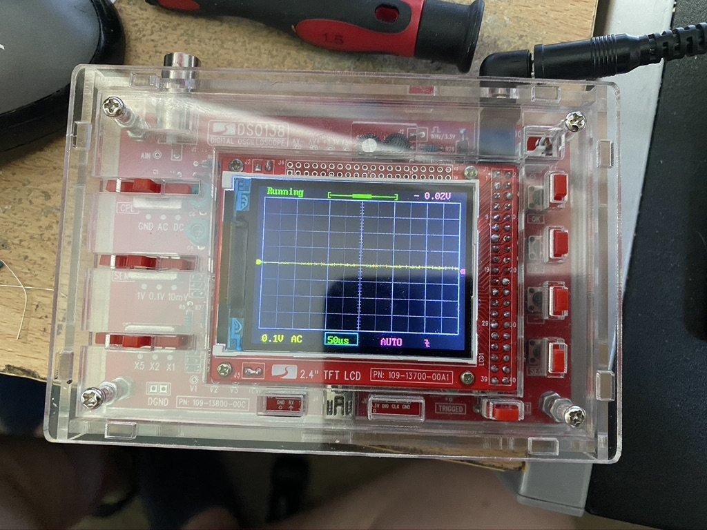
I also spent yesterday afternoon following this rather good tutorial on how to build the case for the DSO138 scope. Whilst I did face some challenges (one switch broke, which required a fair bit of rework to replace) It went really well and enjoyed using my frequency generator and following this good tutorial on how ot use it. This will be very useful when I need to test the VFO when the rest of the components are complete.