40m propagation / Kanga Kit / Intermediate Exam news !

Its been a lovely warm weekend down in Dorset, and that seems to have affected the propagation. I had a great time on FT8 and JS8 Call, reaching amazing distances and really good signals being put out and received. I had many logged contacts and good signal reports.

40m got *busy*

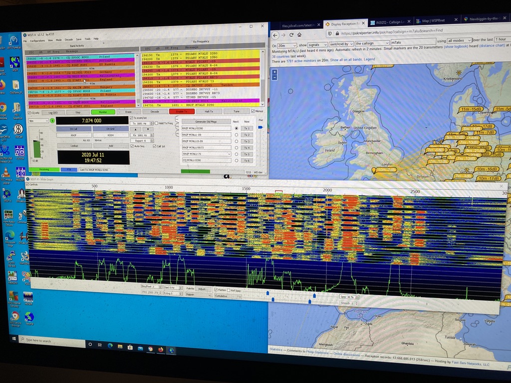
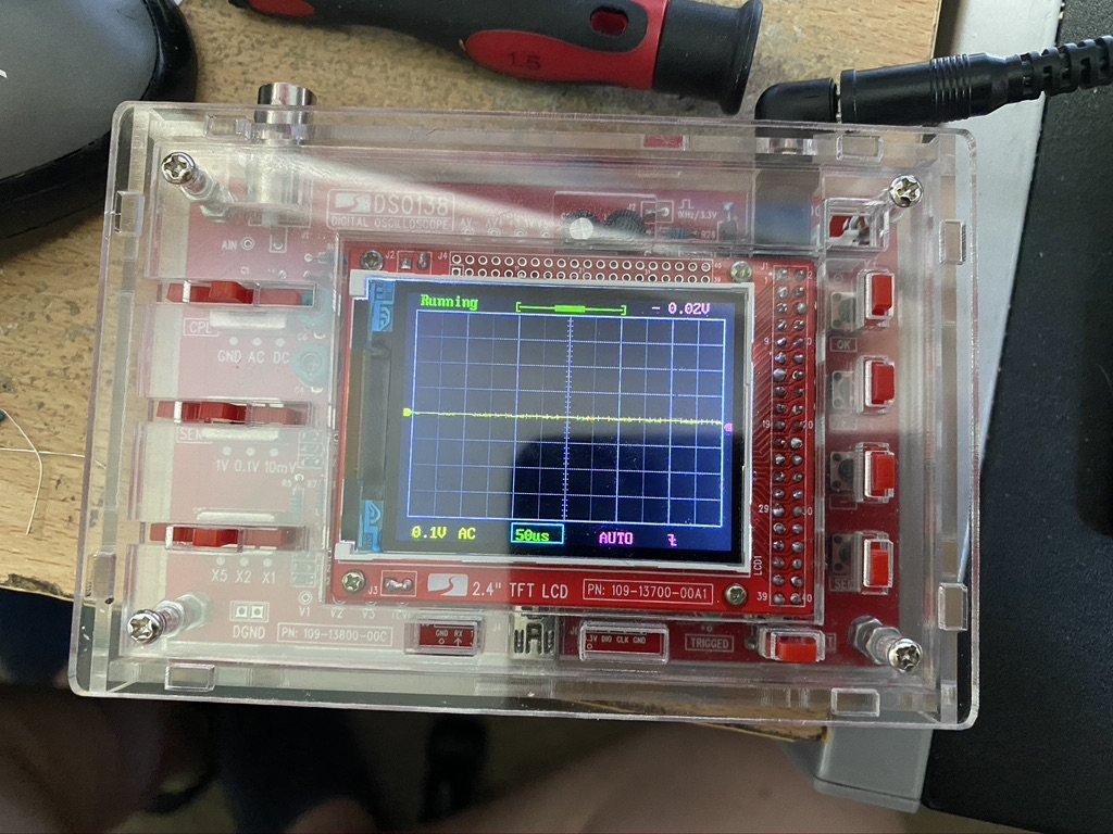
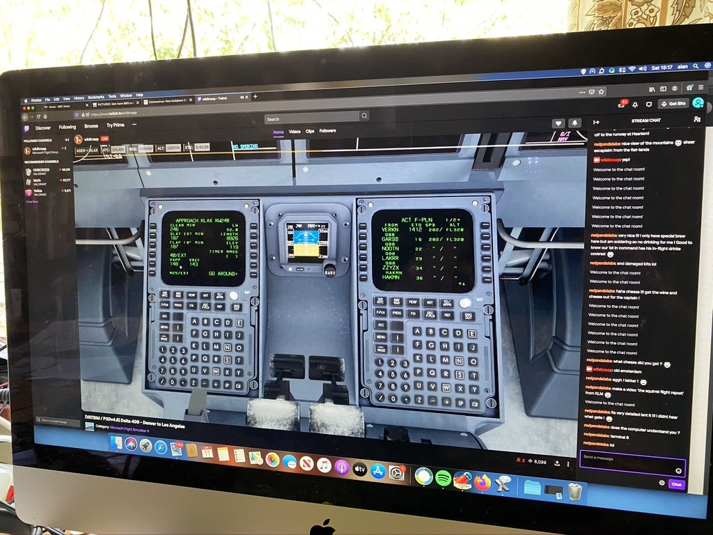
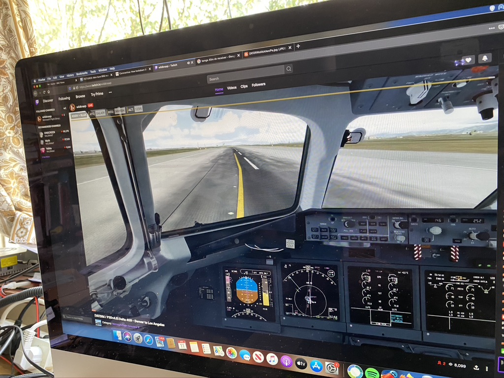
By the evening 40M got as busy as I have *ever* seen it, as shown in the picture above i switched about the bands and was making contacts on 15M as well, it was the best conditions I had seen so far !

Resume work on the Kanga Kit !

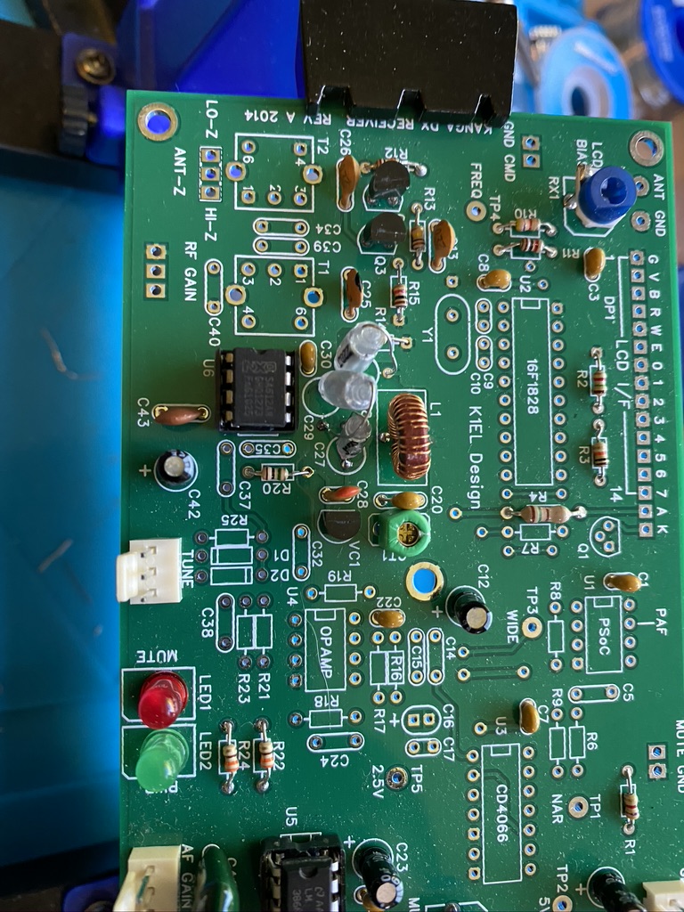
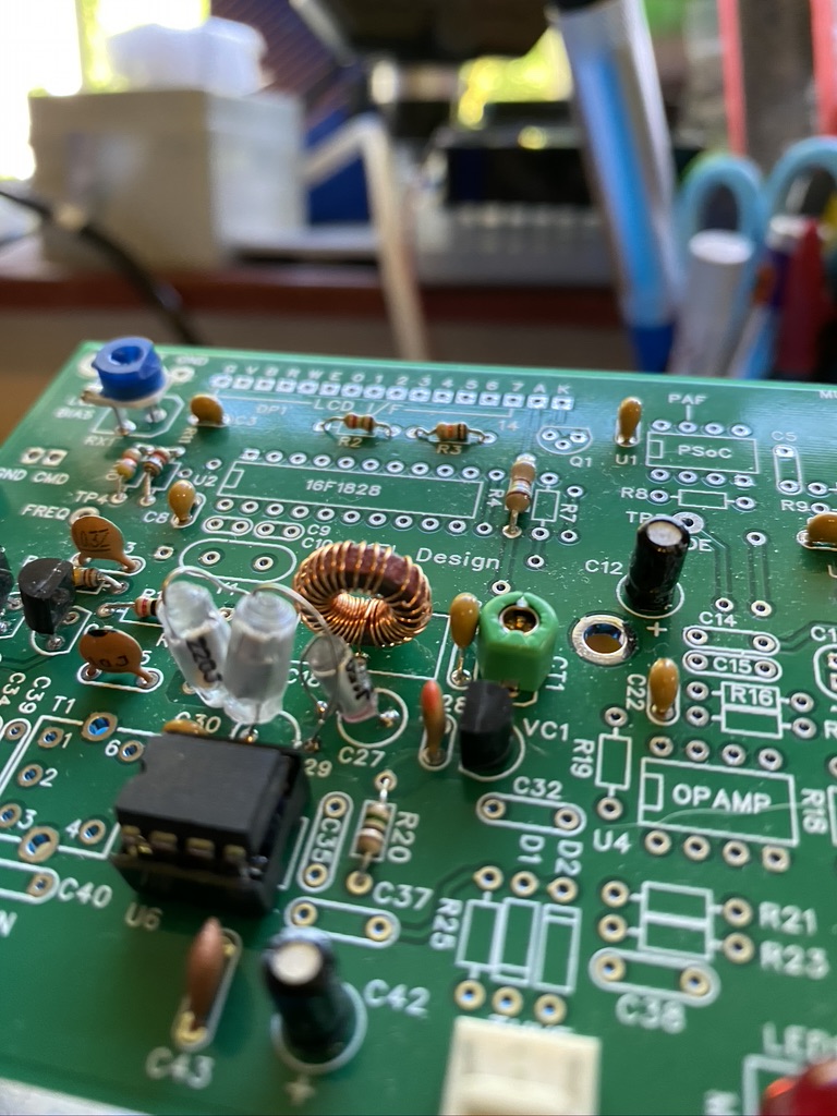
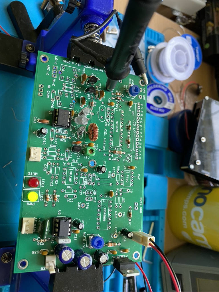
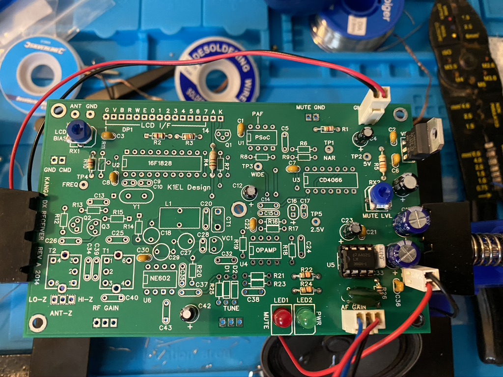
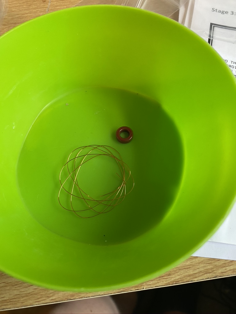
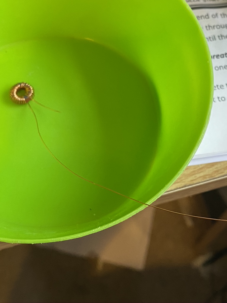
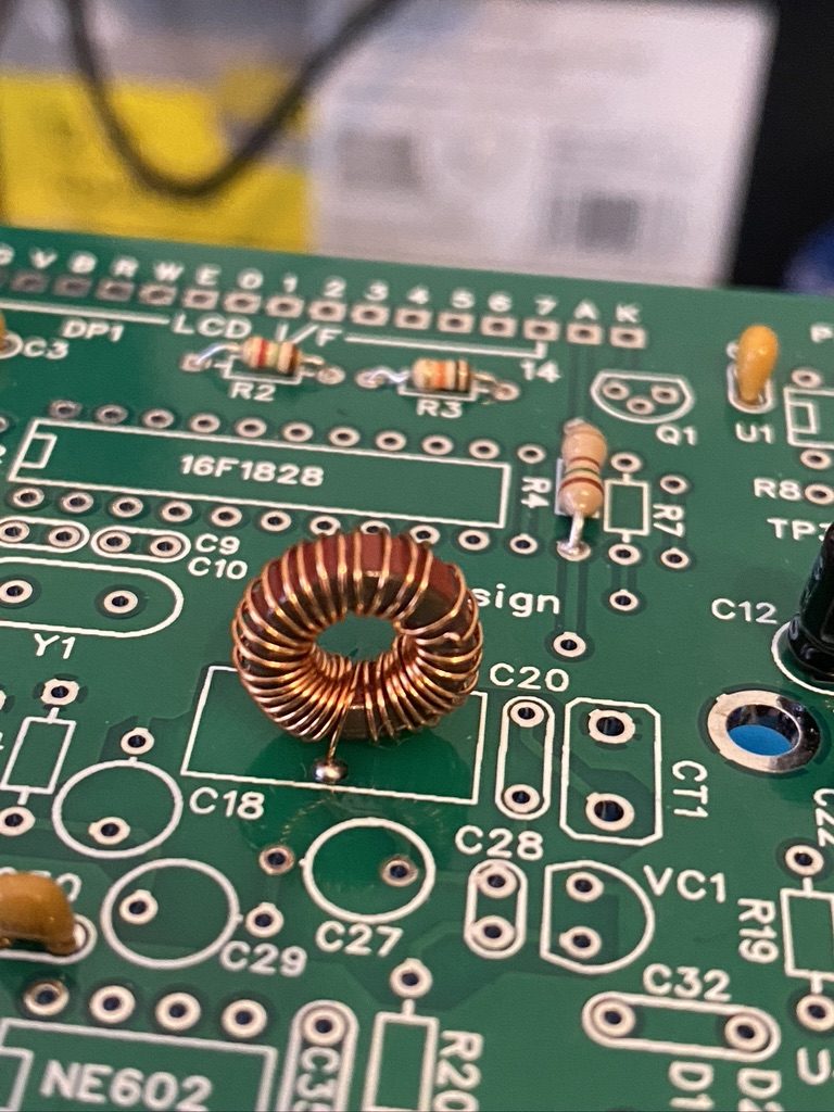
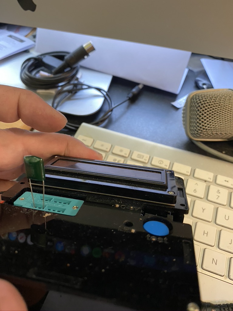
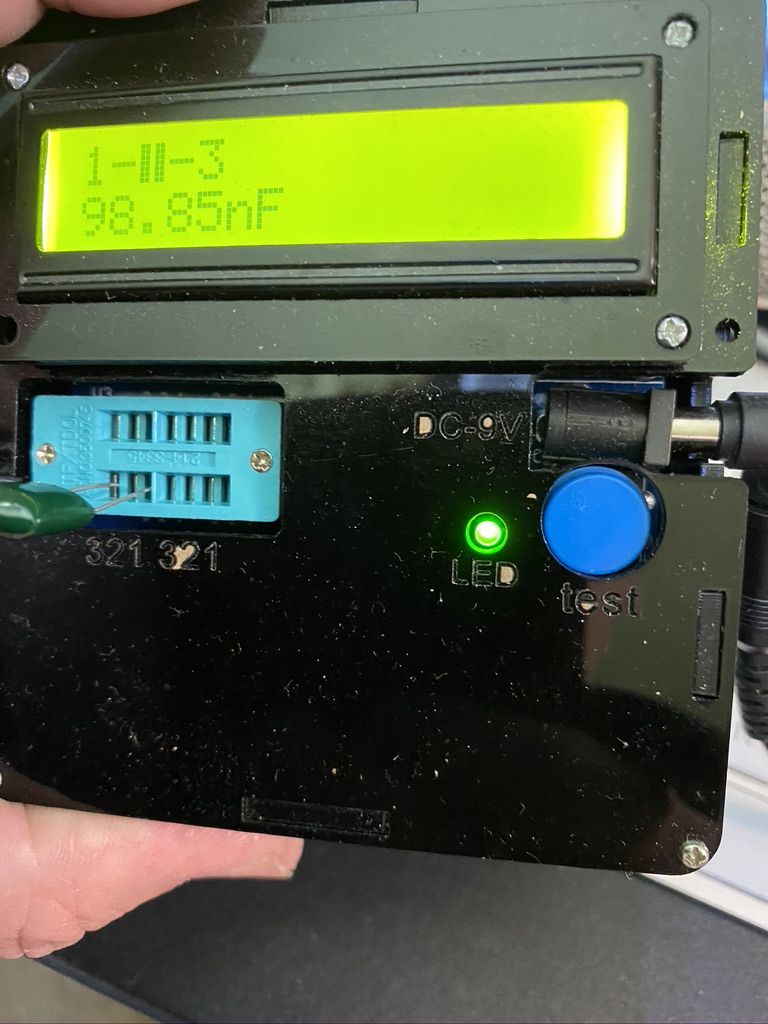
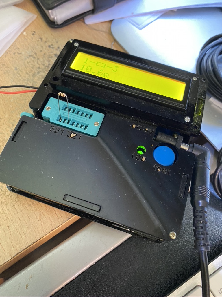
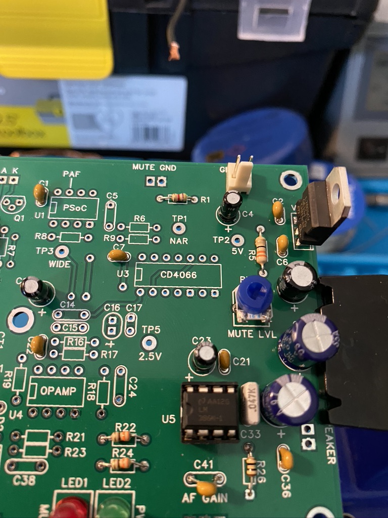
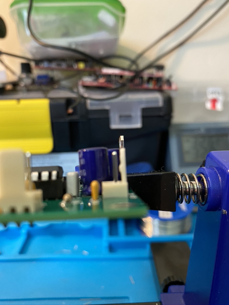
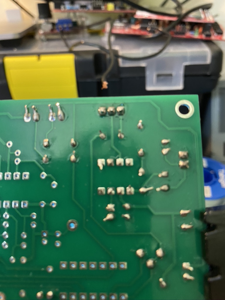
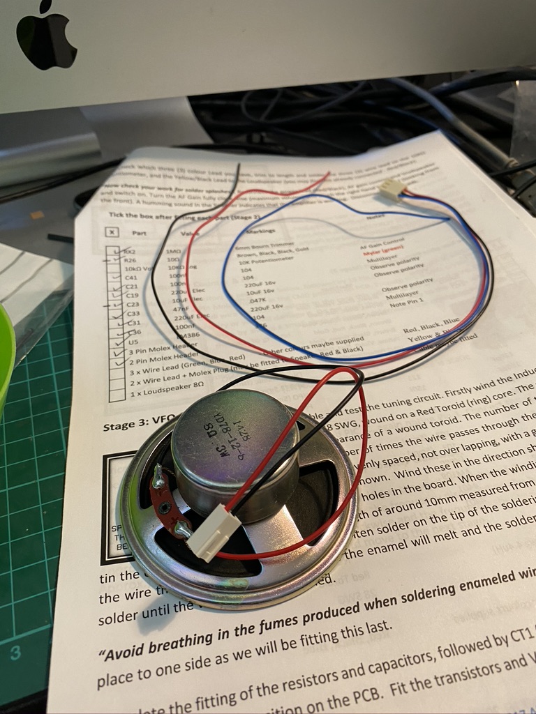
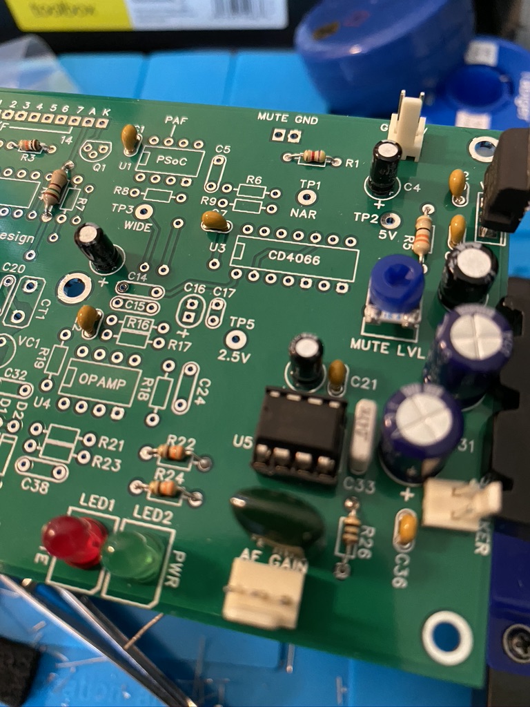
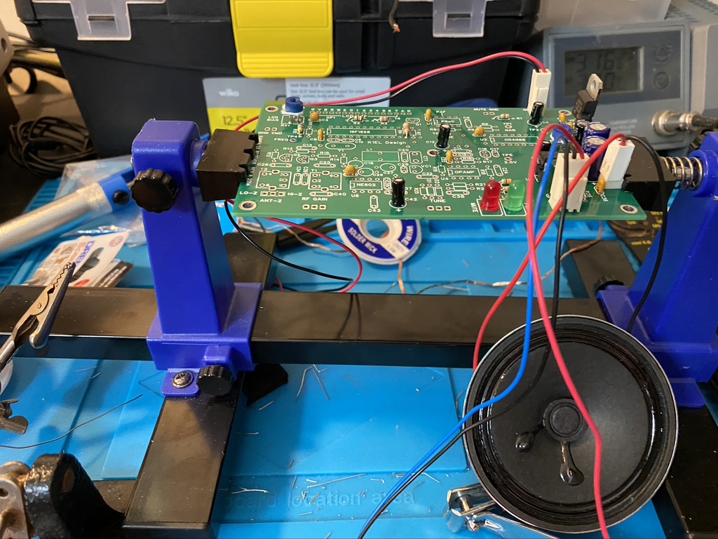
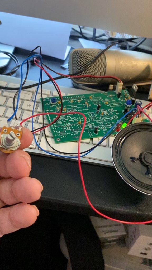
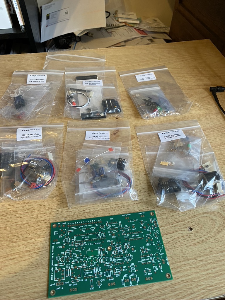
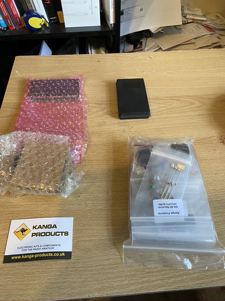
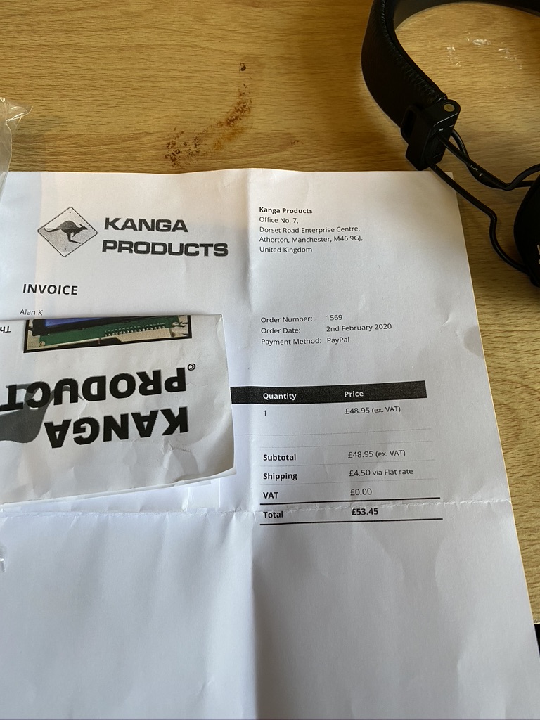
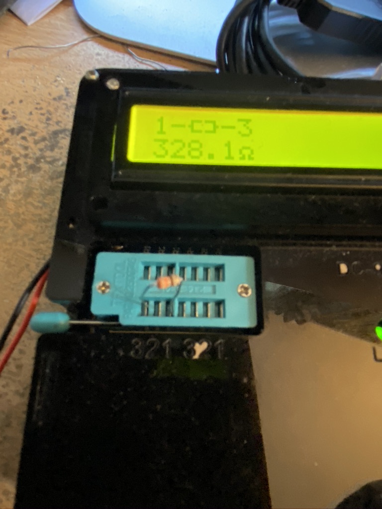
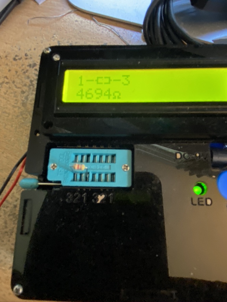
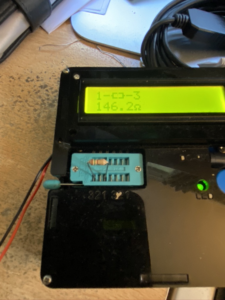
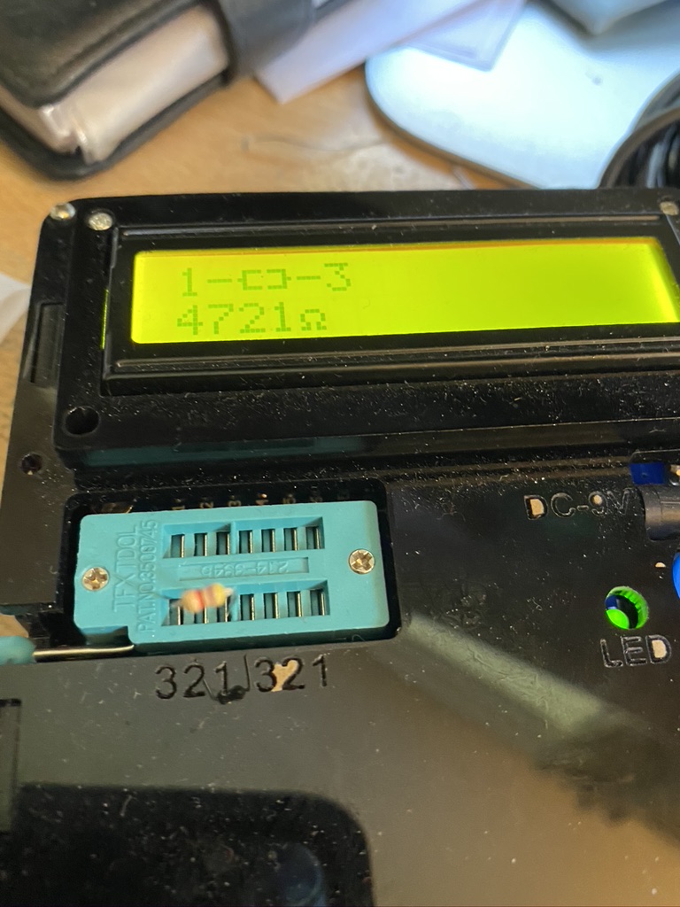
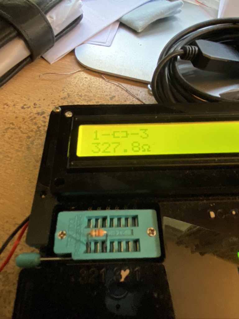
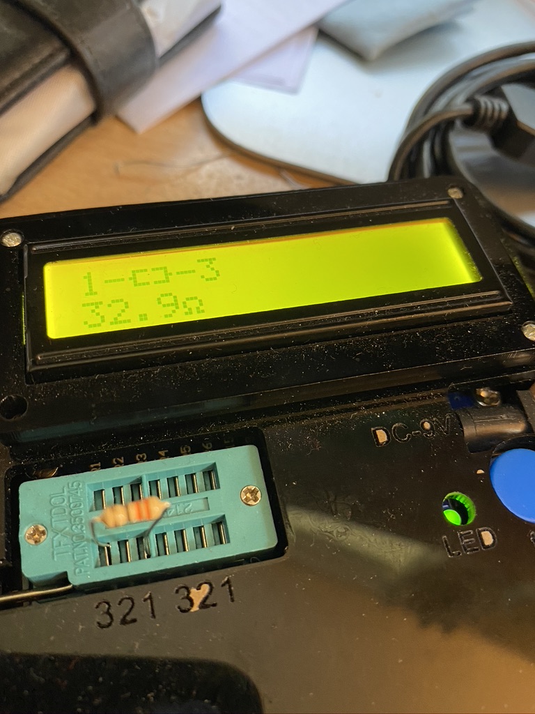
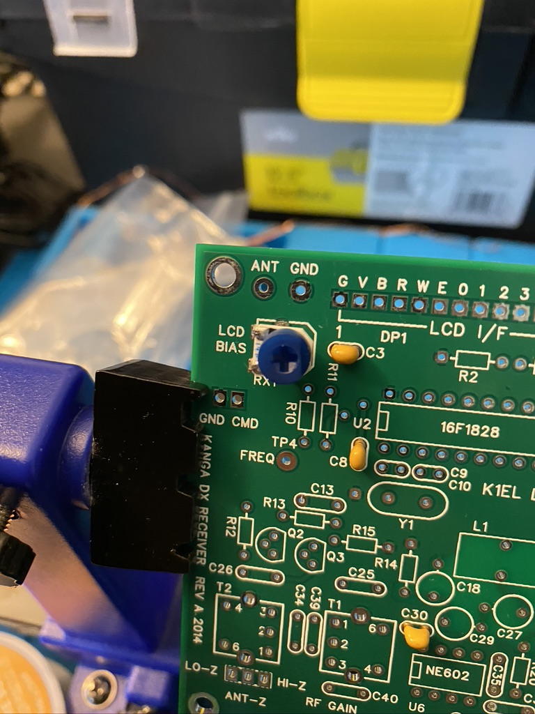
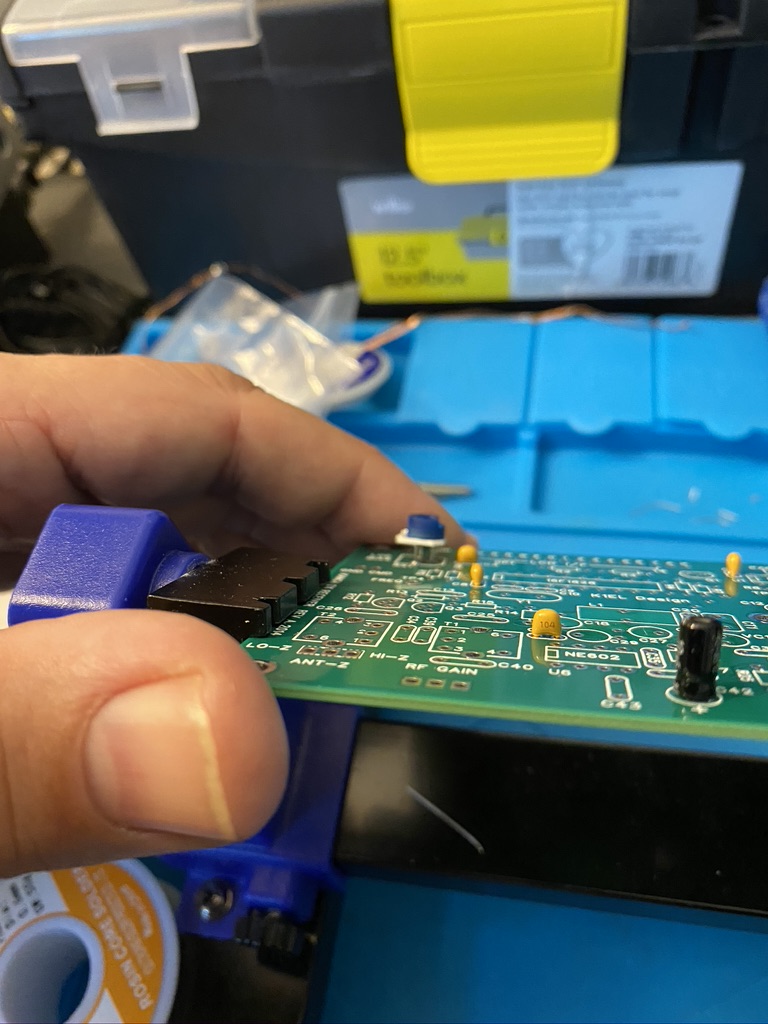
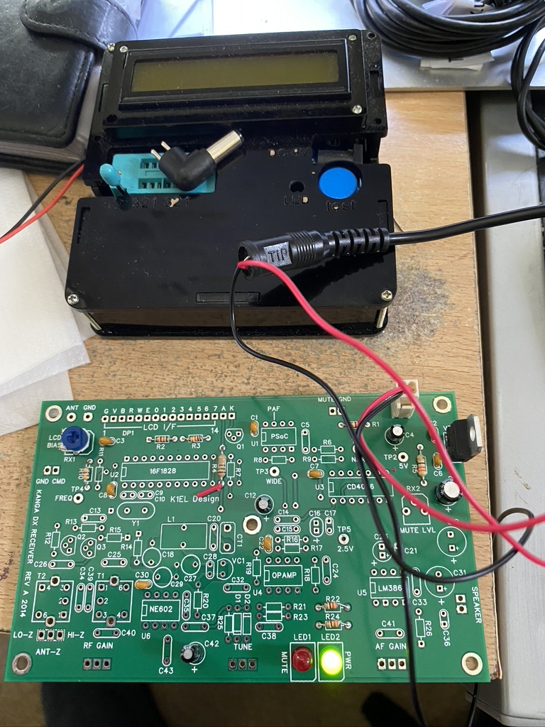
After a break of sometime, I have resumed work on my Kanga Kit – this fits in with the news I’m putting below, but I have a big thanks to John Clements who helped me fix a fault with the kit I was unable to locate. John found the issue (soldered pin-header together – hidden by the plastic) and returned the now working Kanga kit to me ! I have resumed work and am taking my time – I’ve completed more work on the resistors and capacitors on the Active BPF.

kanga kit with added capacitors for BPF stage

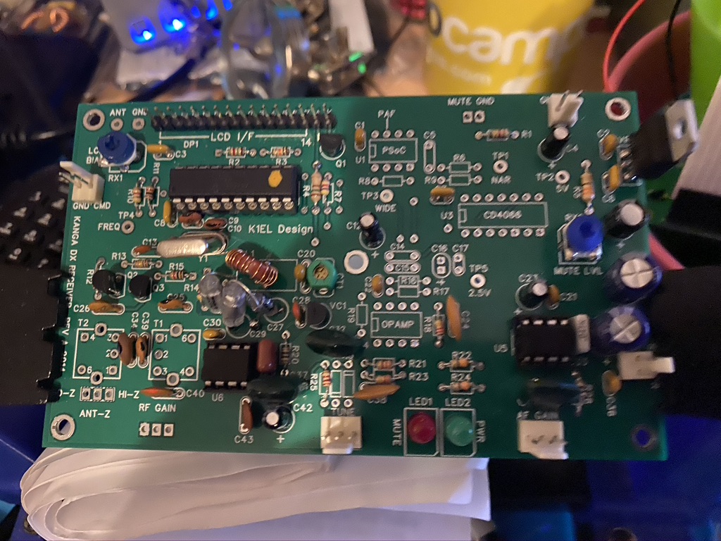
I’m taking my time, esp as the board is now quite ‘busy’ – the next step is to add diodes and IC’s. Its really close to completing the build, but taking my time to ensure no more mistakes !

RSGB Announce Intermediate Exams on-line !

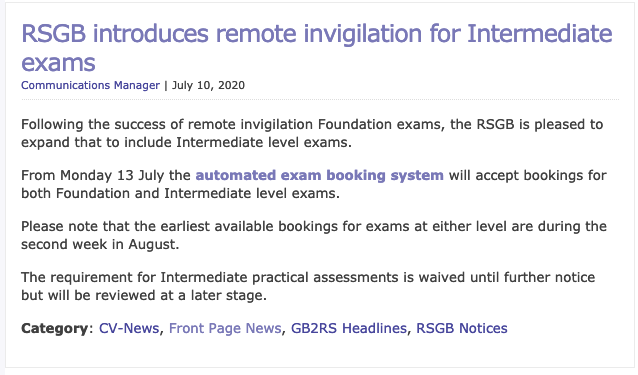
As shown in the picture above from the RSGB site Intermediate exams will be available from the 13th ! (in 8 minutes time as of writing) i’m very excited that i will be able to book my exam and get use more wattage but also gain more insight to a very interesting hobby as I continue my amateur radio development.

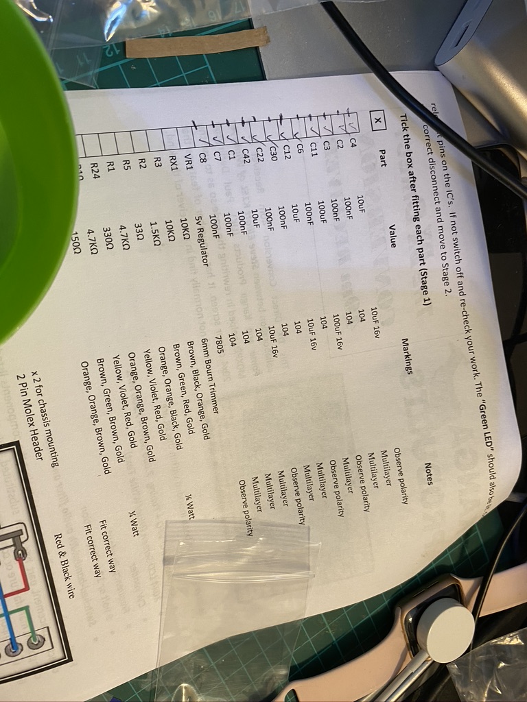
Whilst the practial assessment is waived currently, i will continue to build my Kanga Kit, so if the issue did come up of what Kit I did build, this is well recorded and documented.

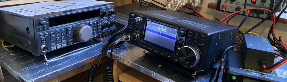
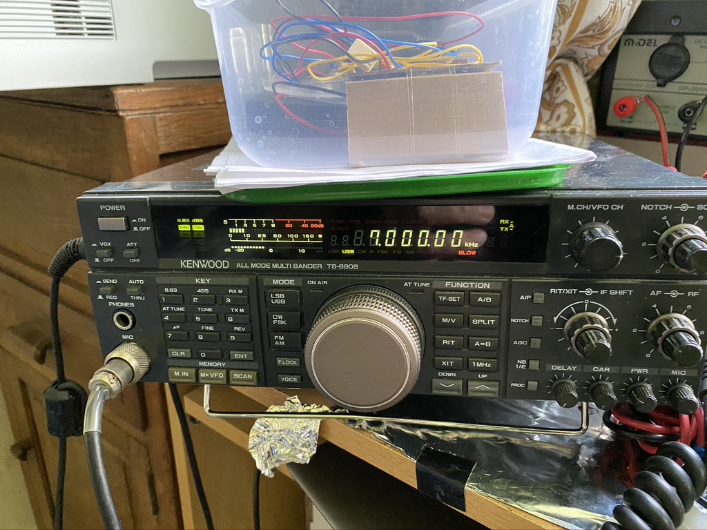
To close the evening off I had a splendid evening enjoying the good propergation and just listening to the QSO’s on 40m. The ICOM’s filter and noise blanker are amazing, SSB has never sounded so good.

The waterfall is incredibly useful for visualising contacts

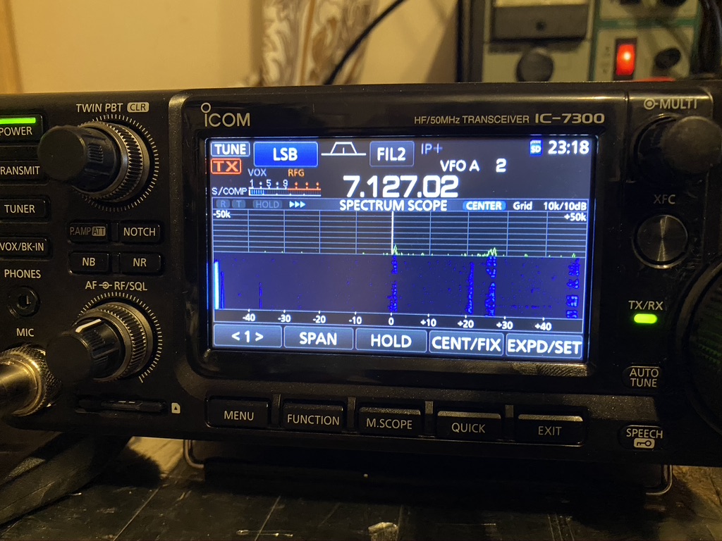
What i really like about the 7300 is the ability to visualize all or in very close range the frequency. I can easily find conversations happening and enjoy what is being talked about and the signal reports. Almost everyone i hear on 40m is using 100W but the distances are still several hundreds of miles – in particular hearing about life on Guernsey was very interesting – seems they are Covid free and back to some ‘normality’.

Well, heres waiting on being able to book my Intermediate Exam and enjoy more contacts around the world !

  • UPDATE – Have booked Intermediate exam today (13 June) for in August for more time to do a structured revision plan and passing !
  • Am still planning to finish my Kanga Kit ! making daily progress !

73 / Alan / M7ALU

Kanga DX Direct Conversion 40m Receiver Kit – Stage 3: VFO & VFO Buffering – Tuning and use of oscilloscope

So having got the lab somewhat tidy (pics and a full reveal will come soon !) i can continue working on my 40m Receiver Kit – having wound the toroid and secured it previously, the next step was to add the components and buffer around the tuning circuit.

I would like to point out (maybe again) that one thing that i think is very much missing from this kit is a schematic of the ‘blocks’ of the decoder. At this stage it would be very much helpful to understand what components and how the modules worked together, in particular when we get to the stage of the ‘decoder’.

Capactors, IC’s and variactor Diode !

I found getting most components on the ‘push-thru’ was easy enough, the only components which presented a ‘challenge were the NPO and Polystyrene capacitors. As you can see the round circles for C27,C28 and C30 are ’round’ enough when the capactiors are verticle.

Capacitor mounting

On the first attempt i tried the ‘test’ method of using a radio tuned to 7Mhz and got nothing at all. It also didnt help that I didnt know what i would be looking, or in this case listening for. I took a break and came back to it the next day.

visually looks fine, but actally a dry join on the trim.

Tracing my work I found that i had left a slight dry join on the trimmer. As i have now aquired an oscilliscope I thought it was the perfect use to find the frequency and adjust it.

We have a 7.5Mhz frequency!

I was so happy to even see a signal on the oscilliscope and also the read on the frequency was not so far out from the 7Mhz. I was lucky enough that the oscilliscope probes come with tuning screwdrivers which are the ‘safe’ type required to tune the trim. I set about tuning to 7Mhz !

Close to 7Mhz

On the scope i could the frequency to read between 6.90nnn and 7.000nn. I thought about trying to see if I could hear anything on my handheld standard (AM) and my transceiver which has more modes (including CW & PSK) as well as specific filters.

7Mhz = beeep

I was very happy to pick up a clear signal on 7Mhz. What was interesting also was that where i have the probe into the VFO / Decoder board, it had turned the ‘wire’ into a small resonant circuit – in fact I could turn my VFO into a theramin ! After 15 minutes of playing wooping noises I set about completing/and tidying the kit up.

I’m really glad that the receiver is going so well – its been all the work I thought it would be but its now very satisifying, esp as its gets more complex.

Kanga DX Direct Conversion 40m Receiver Kit – Stage 3: VFO & VFO Buffering (Toroids)

The next stage in the kit was to complte the Variable-frequency oscillator (VFO) & VFO Buffering. The first part of this is quiet detailed and delicate, and wanted to do it seperate from the regular resistor and capactiors stages. The instructions do say to add the Toroid towards the end of mounting but given its positon on the center of the board, it wont get in the way from what I can see.

Toroid poisition is L1

I done my usual task of seperateing the parts out in the small bowl I have, even tho there are only two parts at this stage, the magent and the 28SWG copper wire.

wire and magnet – how ti comes out the pack

Firstly i straightend the wire out to remove any kinks, and using a combination of tweezers and my hand started to thread the wire thru. I kept 10mm (maybe +/- 2~3mm) as the winding start. After 10 winds, and still keeping a tight hold of the magnet and wire, not knowing how it would ‘behave’ i took a look at how it was ‘forming’ on the magnet. So far so good, so kept winding. I found that towards the end it was getting quiet tight, but not difficult, sliding the wire up and around the magnet gave me the space I needed.

I felt having none done this before, it hadn’t turned out too bad, there was one little kink in the wire, but in 33 turns, thought that was an ok ratio for a newbie toroid winder like me !

I then set about how to mount the toroid on the PCB. I used a reference picture of how other people (or person) had mounted it. The next step was to cut then tin, so i trimmed the wire back to a length that would help with mounting ahead of tinning.

For tinning to work, i turned my soldering station upto its max power of 450c which created the desired ‘bead’ of solder and melted thru the coating on the wire, leaving a nicely tinned wire to solder to.


‘top side’ soldering

My soldering workstation is great in being able to ‘flip’ so i can easily solder components when pushed thru form the top. The Toroid presented a channege as there was no real way to exert any ‘force’ and flip the board over, nor did I really want to try the method of putting a small blob on one hole then to heat and push thru, as I thought the pressure would disfigure the winding. I’ve not used this ‘technique’ before, but I decided to use a ‘holding’ weld solder spot from the top on both sides. Indeed, rather than even move the board from the holder, I roated the entire board 360 so I could top-solder the other side in. From what I could see, this has worked very well with a secure toroid and good spaceing between the start and the finish.

Oscilliscope – now in case.

I also spent yesterday afternoon following this rather good tutorial on how to build the case for the DSO138 scope. Whilst I did face some challenges (one switch broke, which required a fair bit of rework to replace) It went really well and enjoyed using my frequency generator and following this good tutorial on how ot use it. This will be very useful when I need to test the VFO when the rest of the components are complete.

Kanga DX Direct Conversion 40m Receiver Kit – Stage 2: Audio Amplifier

I set about the same method of splitting out the pre-packed components into a bowl making selection and testing easier. The instructions again are quiet clear, with good values of the resistors and capacitors.

I did have to overcome a few mistakes, but whilst it was a ‘mistake’ for the board, its a good exercise for me in being able to correct issues, in this case the Mylar 100nF capacitor. The mistake I made was getting in confused with the smaller 104 labelled capacitors. I looked up a picture of a completed board, and can see that the ‘mylar’ (green) capicator was needed to be changed. Using some solder braid and solder sucker, I was able to cleanly correct the incorrect component.

So I had an email ping me that my recently re-aquatined friend Pablo was flying (in real time), and was able to watch the video of his flight and the real-time radio transmissions. It was utterly amazing as people responded to the flight requests ! It was good having some ‘chat’ banter as well.

I set about fitting the one IC at this stage, the LM380, a simple audio amplifier and the required molex heads to connect the loudspeaker and variable resistor, all which went on well using the ‘solder a little’ then push thru method to get them nicely aligned and snug to the board.

So by now it was abou (I think) an hour into the build and i re-checked my work, having had an issue on an IC holder on the frequncy counter, didnt want to repeat the same issue. I found that i was a little light on the solder, so add a tap more just to make sure the pin would have good conductivity. Pablo had given us a great filght over the Rocky Mountains and had landed his jet via his controls, with an massive to taxi to the gate !

So time had come to test, i hooked up the PCB to the mains adaptor on 12v and hey presto, a healtly static sound came out the speaker. I could use the variable resistor to control the volume, so everything was worknig perfectly !

I had a great time building so far, more so thanks to the relaxing flight and chat with Pablo. I headed off to relax a little more with some wine and cheese myself 🙂

Kanga DX Direct Conversion 40m Receiver Kit – Stage 0 & 1

Its a long weekend here in England (Friday and Monday off work) so am starting on the Kanga DX Conversion Kit. I’ve bought this for when I can have my practical assement as part of my Intermediate Radio Licence.

Stage 0 has been getting enough practice and all the other pre-reqresuits ready, of course these are not in the build instructions, but faciliated the purpose and ability to build and test once complete.

  • Setup Mast to Receive on 40m – DXCommander
  • Receive Morse on TS-690 on 40m
  • Build up soldering skills on other kits (Volt Tester, Oscilliscope, Frequency Generator, Frequency Counter)
  • Lab Equipmemnt – have added a USB Microscope as I think this will be very useful

With that I laid out the kit and also pictures of my details so when the assement comes, they can see I have actually built the kit.

I printed out the instructions from here which are practical, but one criticisim I have is there is lack of a circuit and block diagram. As this kit is built for radio amateurs I think that should be included.

I was very impressed with the clarity of the instructions, in particular giving the colour codes for the resistors. As I have a tester I used that to confirm the values, but it is a great way of ‘learning’ the resistance bands.

I found getting the trimmer ‘RX1’ to be quite fiddly, as it sits a little off the board and the ‘legs’ bend in a little. Using a fine pair of tweezers allowed the legs to be put into place with the correct height adjustment.

I then set about putting the LED’s in making sure that I got the +/- the correct way around. I used this site to confirm and from the markings on the PCB assume the ‘notch’ edge to be negative/flat as per the picture.

its alive!

It had taken me about 2 hours of patient and methodical building to get all the components in. I did find however that *ahem* someone had left the voltmeter on and the battery had run flat. I popped out for my daily ‘essentials’ hoping to get a PP9 but no luck, so have ordered a pack of 8 from Amazon here. In the mean time i adjusted my variable PSU and hooked the stage-1 completed board up and huzzah – I have LED’s – which i think confirms the power circuit is working correctly !