- bit of a longer post today so grab a cup of tea is recommend, else scroll through the page until you get to the bit you want to know about
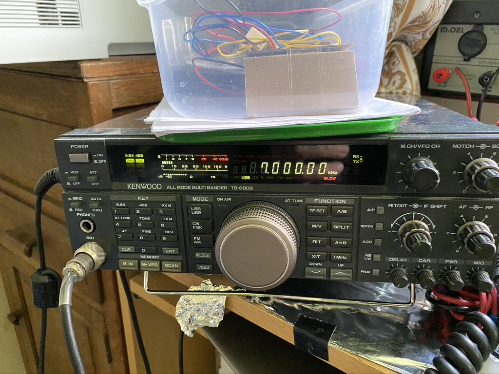
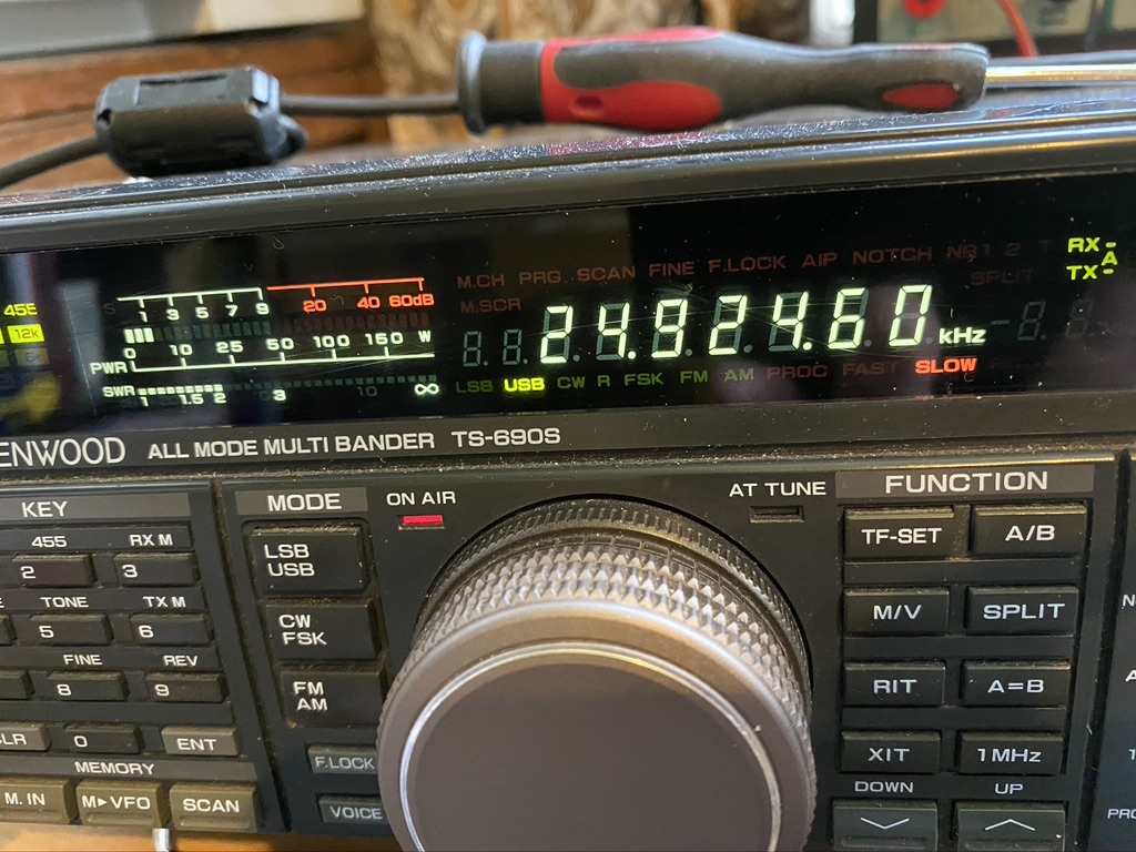
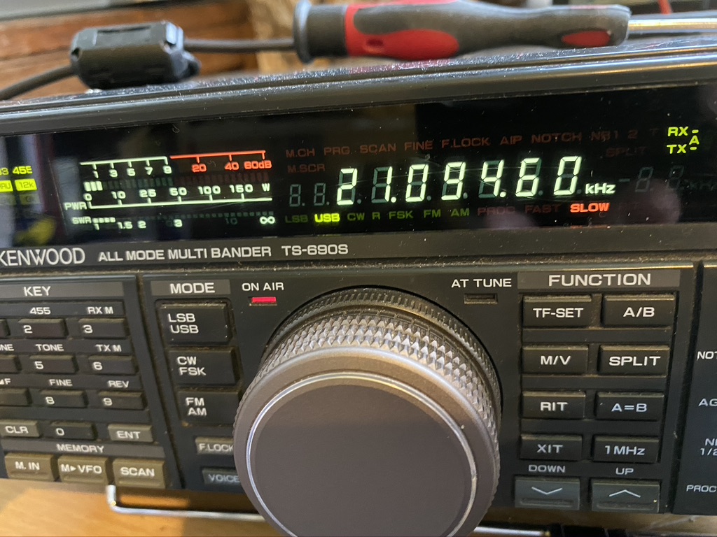
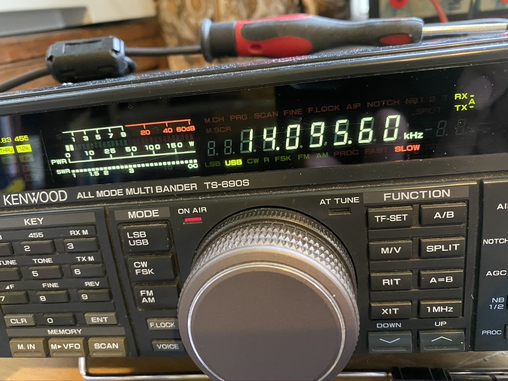
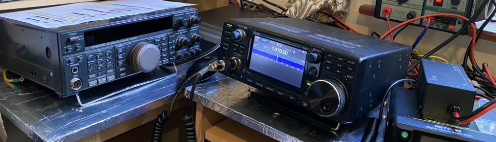
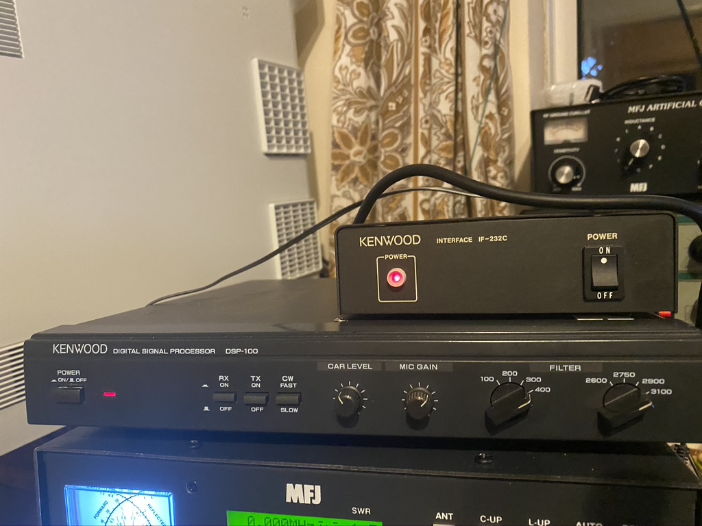
Several weeks ago I was browsing the local 2nd hand radio shop where my TS690 came from, and amazingly they had the DSP-100.
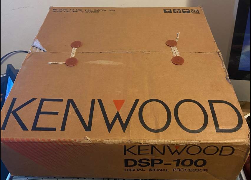
The DSP-100 is one of the first ever Digital Signal Processors. Kenwood were pretty ahead of the game when they released it. You will see all the filters and features you see in this unit in most modern transceivers, but this is (I guess) about 20+ years old, and are hard to come by. I dont mind saying this unit, 2nd hand was £333 ,which is only £40 different of what I paid for the TS690S, but what it brings to the radio is RF filtered and processed. The promise of ‘hi-fi’ quality SSB, AM, CW and RTTY was too good to pass up. And it looks gorgeous too 🙂
When I first set it up with my TS-690s I connected in my xggcomms Kenwood interface I started running into issues. I honestly believe this is no fault of the xggcomms device, but moreso on how the RS232 signal from the DSP-100 unit is processed and fed into the transceiver. Its fair to say whilst I was overjoyed in having the DSP, alot of what i do requires a good CAT connection to constantly adjust the frequency (FT8 & WSPR), so I reverted back to the Xggcomms interface only and started investigating.
Upon searching, other people had experience similar, but not identical issues. The key to fix this was the IF-232C. This translates the serial input into signals at the correct levels for the DSP & the TS690s.
Up until now I have been using a laptop, which had become increasingly over burdened with USB dongles/hubs coming out of it, also getting the computer to be ‘RF Friendly’ and grounded proved a challenge. The only way i could see to easily and reliably RF was via the USB port, and this little lenovo laptop computer already had *alot* coming out of the USB ports.
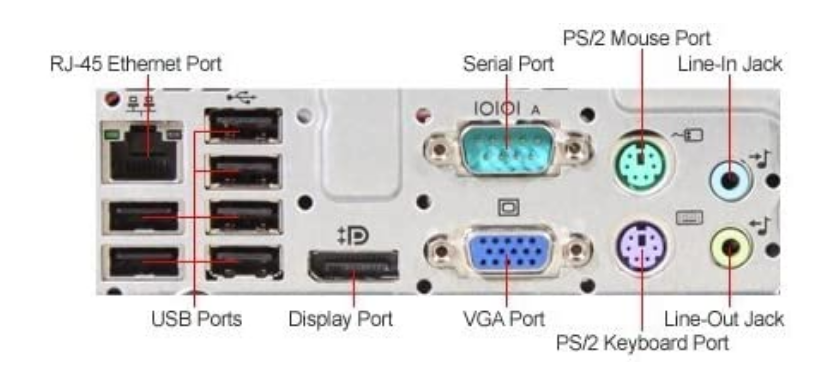
With that I decided to get a dedicated full-size ham-radio PC. Nothing expensive or new, in fact I was looking for ‘older’ models with a native DB9 Serial interface so USB to Serial issues would no longer be a problem. This HP Elite 8200 met the specification needs for what I would be using the computer for and was a reasonable price/availablity. I could add all the audio inputs and outputs to the native connectors and also use the on-board serial (or so he thought…)
Having migrated PC i went about installing first the apps I know, namely Fl Digi and FL Rig. I have been using these for sometime for WeFax and love getting the images in. The good thing about reducing the QRM, i can visually see it has been reduced, as I will show later.
I did run into some issues with communicating with the PC, the Serial Port settings had to be changed on the PC also, by now I had also discovered i had ordered the wrong cable from RS Electronics, but have a replacement on the way. I went back to using a USB to RS232C interface for now, which after some tweaking worked. I’m sure I’m not the only person who would still setup a IF-232C, so here are the settings I used between my PC and the RS232C.
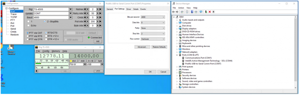
Incase its hard to read on the screen, heres the tabulated form
| Setting | Value |
| Bits Per Second | 4800 |
| Data Bits | 8 |
| Parity | None |
| Stop Bits | 2 |
| Flow Control | Hardware |
| Advanced | Leave FIFO Buffers at max and on |
In the FL Rig for the Serial port the settings are as follows (Select TS450S as the transceiver) :-
| Setting | Value |
| Baud | 4800 |
| 2-StopBits | Enabled |
| PTT via CAT | Enabled |
| RTS/CTS | Enabled |
| Retries..Byte intv | Defaults |
| Init (Click) | Connected |
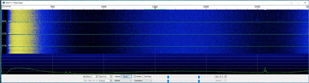
Now I dont mind saying that I’m still learning, so understanding what filter to use when is very much a case of ‘try it and see’, but i will show a comparison between before I started all the QRM clean up and the acculmation of what I have done so far *plus* the use of the DSP-100.
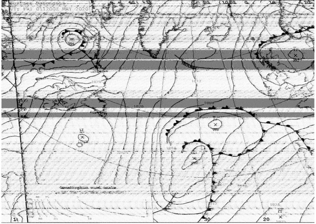
As you can see in the above image, there is alot of QRM in the picture, the ‘banding’ consistant across the image, in this case probably caused by the Ethernet over Power adaptors, is very clear.
Here is a scan today, same antenna, but will all the additonal work to reduce QRM and the DSP in Receive mode filtering.
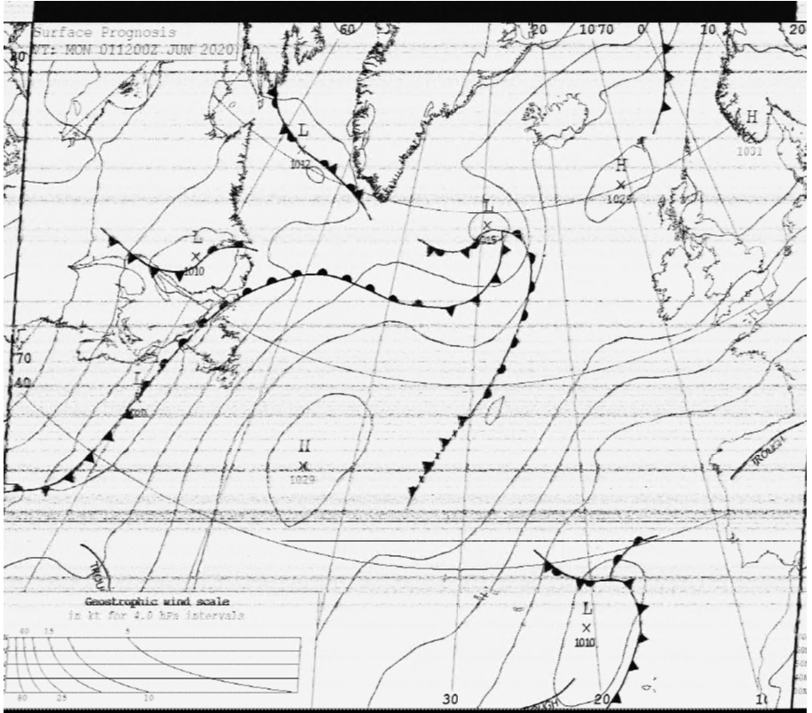
When less electical items in the house are running, namely fans, washing machines and the like here is an example image. Again, this is the same antenna, same external line filters/chokes and the DSP and recent QRM work outcome.
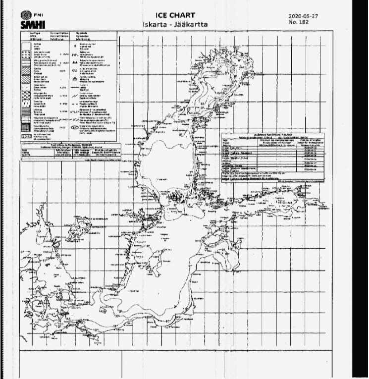
The ice-chart from Hamburg is the equivlant for me as the last row on the eye-test exam. The letters on it are incredbly small and the details/dots equally so. Whilst with a zoom there is some slight distortion (so more to be gained!) there is a total absence of the QRM which was so present in the first WeFax image shown.
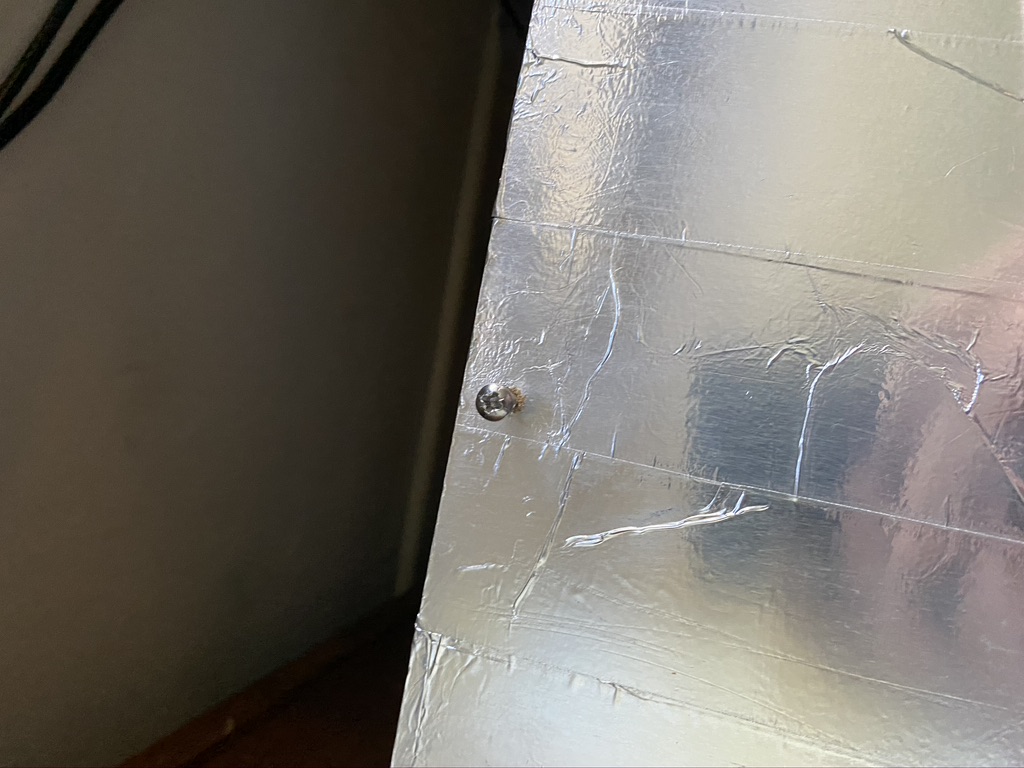
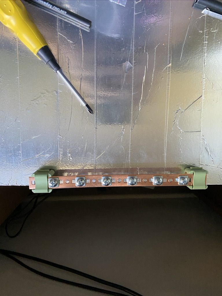
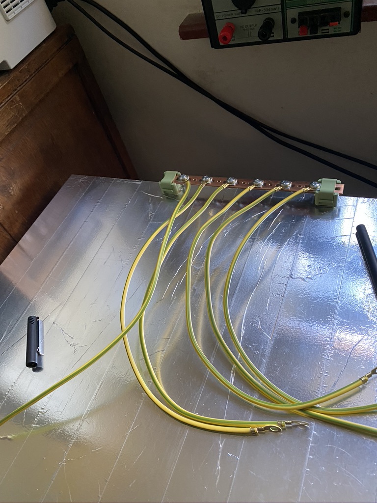
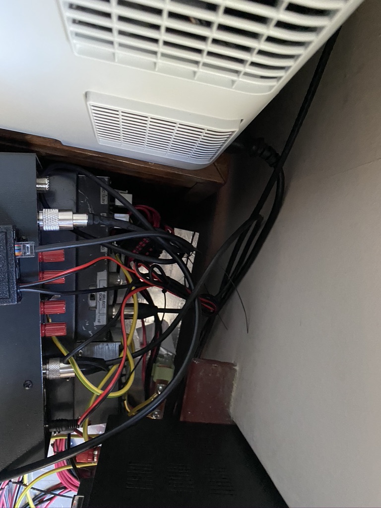
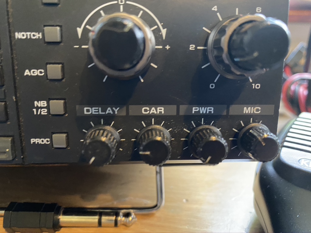
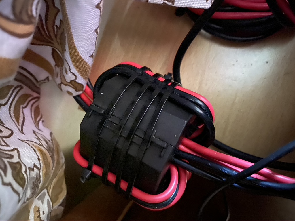
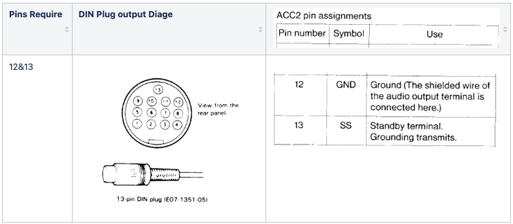
I am adding a MFJ-1026 to the mix now (Thank you Nevada radios, you are doing a great job during the lockdown !) and I cannot thank Steve from Xggcomms enough for the assistance he has given me. I asked Steve for some help on how would I go about connecting both the xggcomms and mfj-1026 at the same time, as they need access to the T/R Control line present on the ACC-2 port. Sure enough Steve was good enough to reply on how to do this, by way of opening up the connector and adding a connection to pin 13 and ground (I used pin 12 for ground).
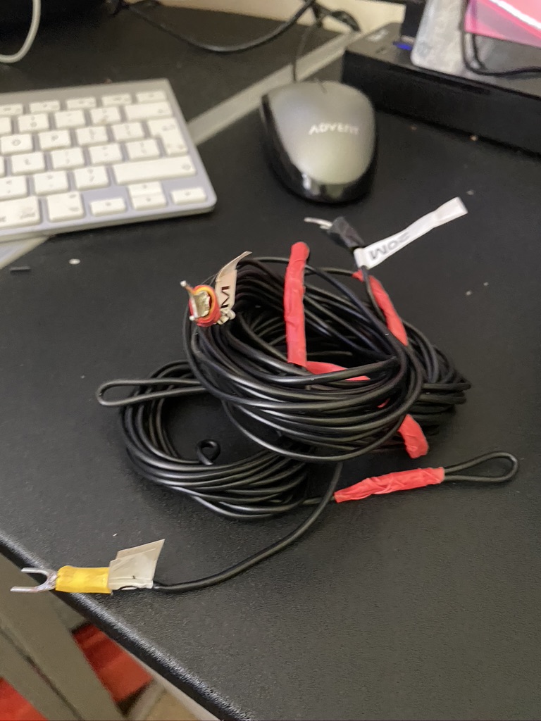
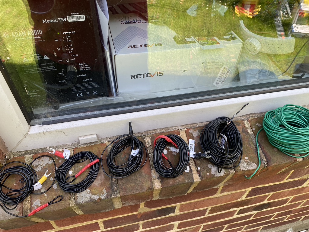
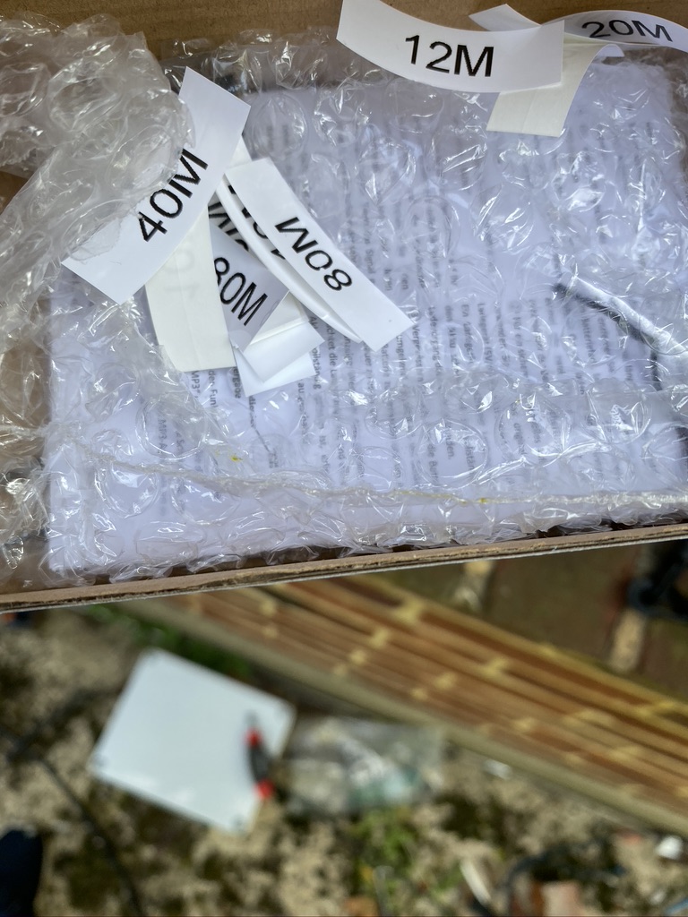
I had recently performed an inventory of all the wires/cables,etc I had, so it was easy to find the phono socket I required to connect the back of the MFJ-1026 phono socket to the ACC2 DIN plug.
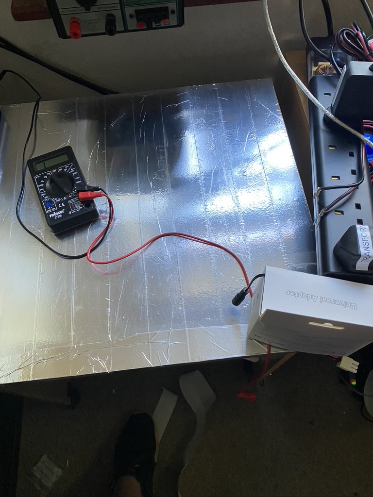
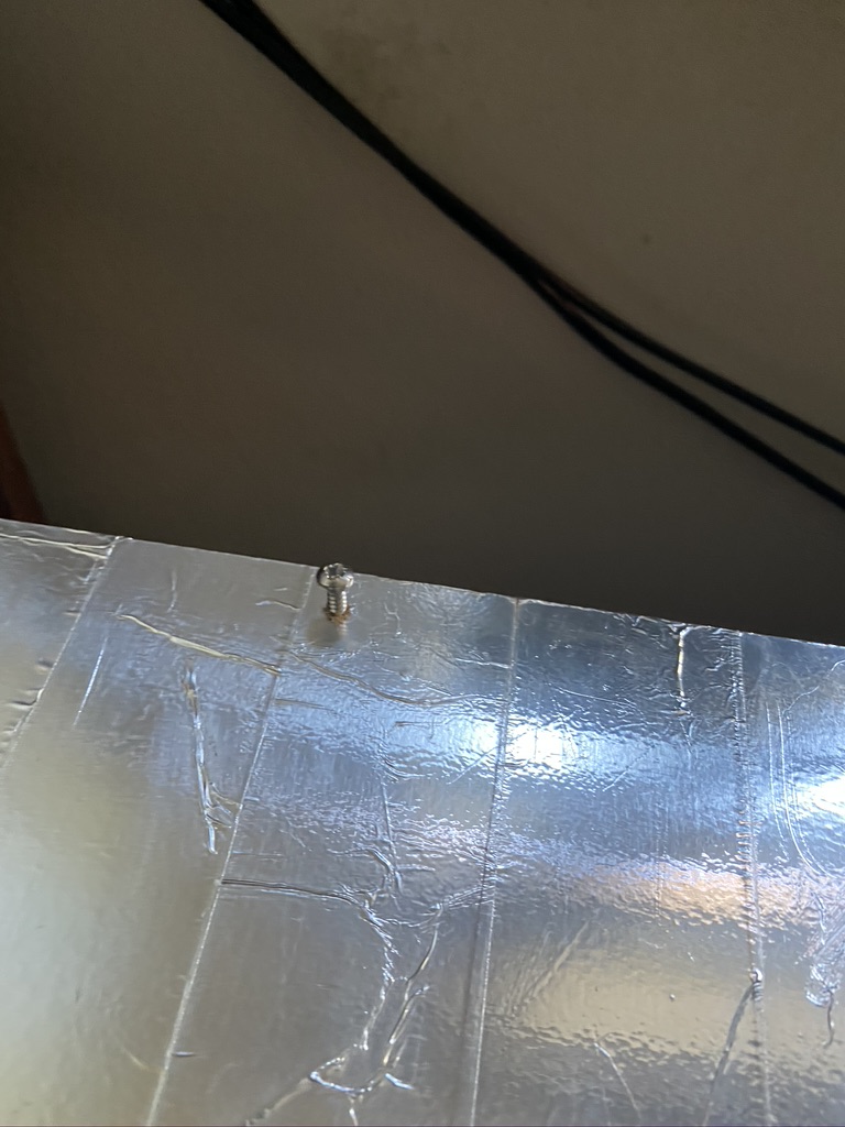
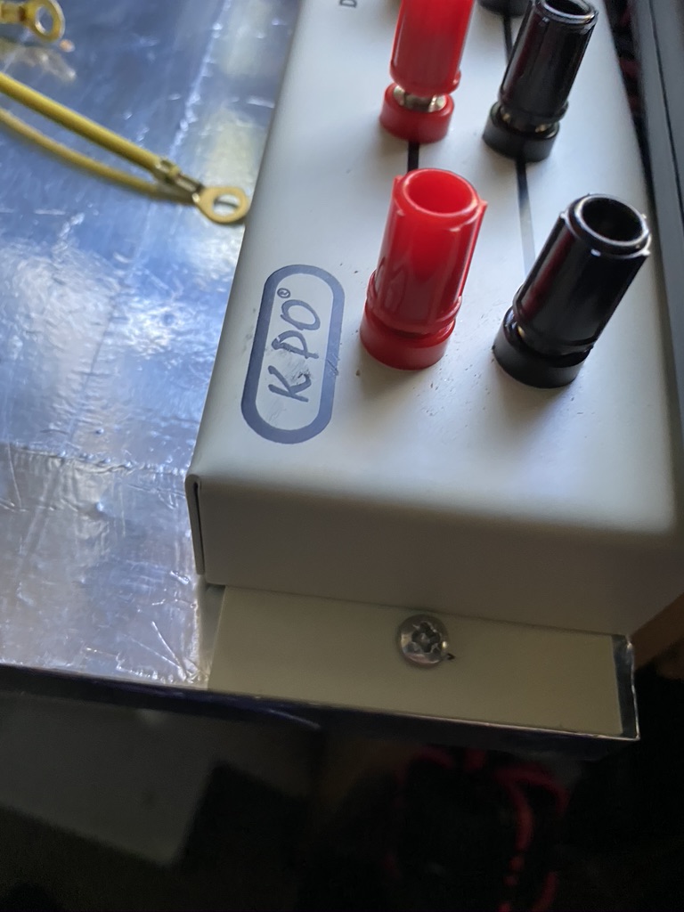
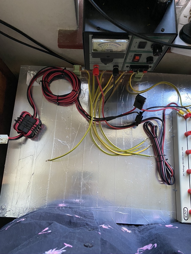
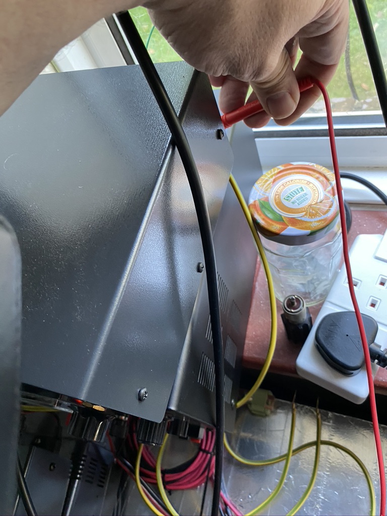
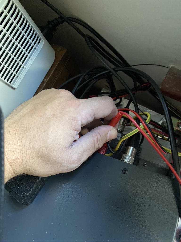
I first tested the connectivity between socket and plug, to ensure it would work correcly before opening up the xggcomms. I am generally unhappy about opening working equipment in that I could break it and make it unoperational, but as Steve had already offered his support should anything go wrong, i bit the bullet and went for it. Needless to say, it wasnt an easy job for me who doesnt do this type of soldering reguarly.
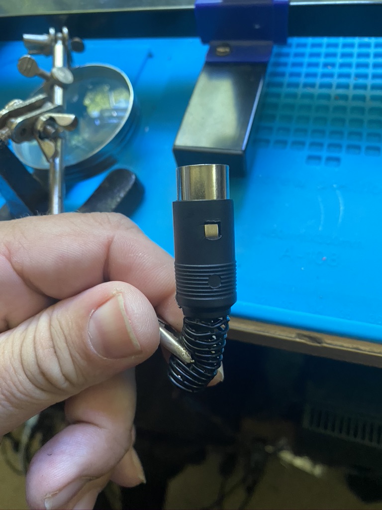
xggcomms intact 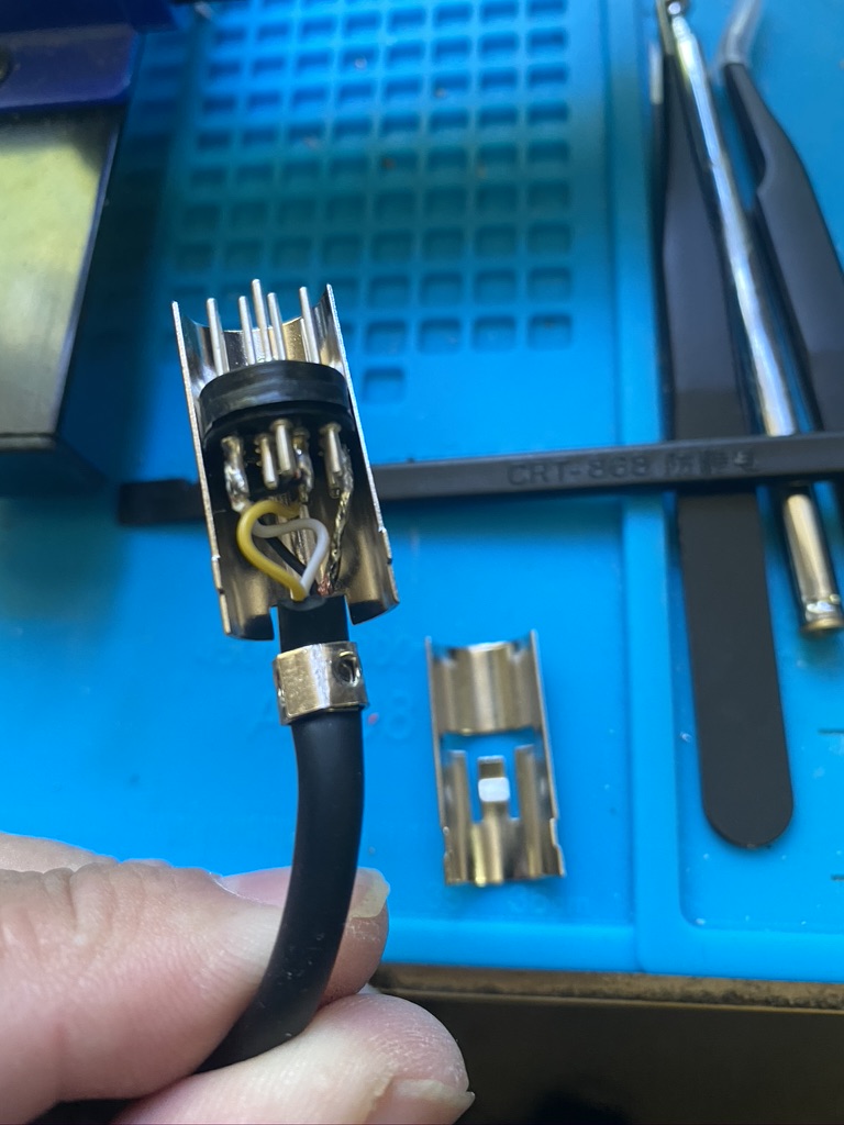
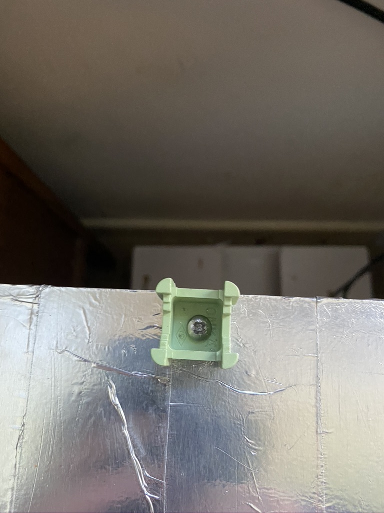
removing the flexible case allowed easy access 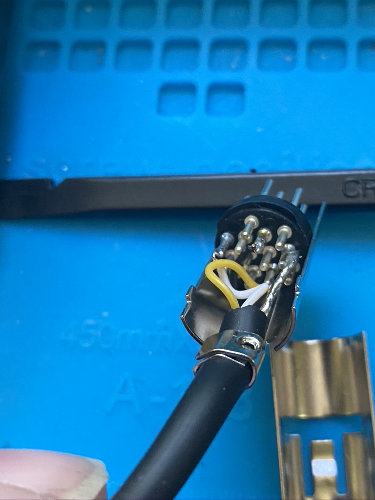
respect for that soldering 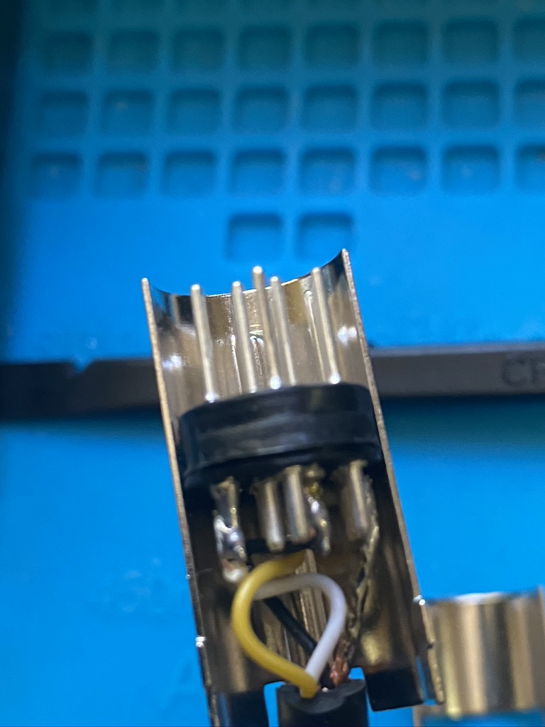
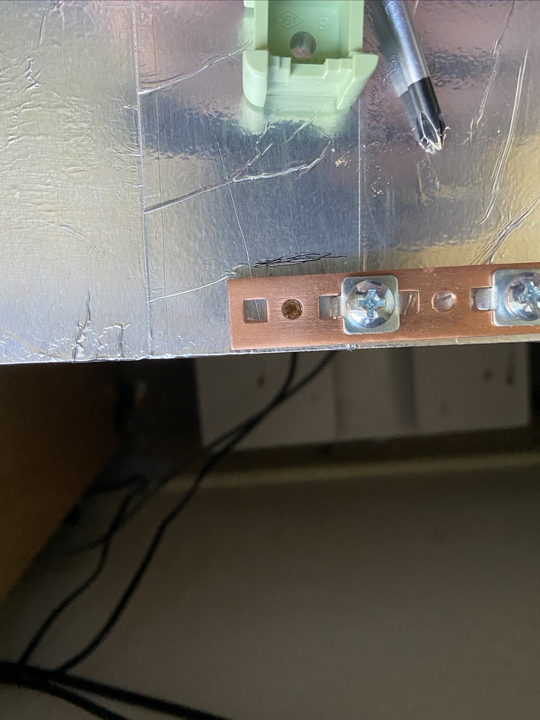
this is going to be interesting.. 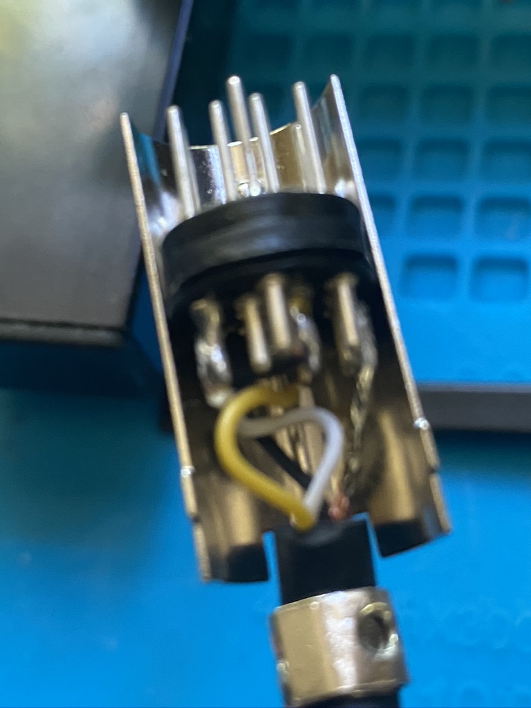
pin 13 & 12… 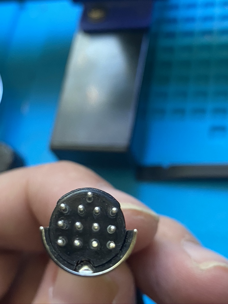
there they are…
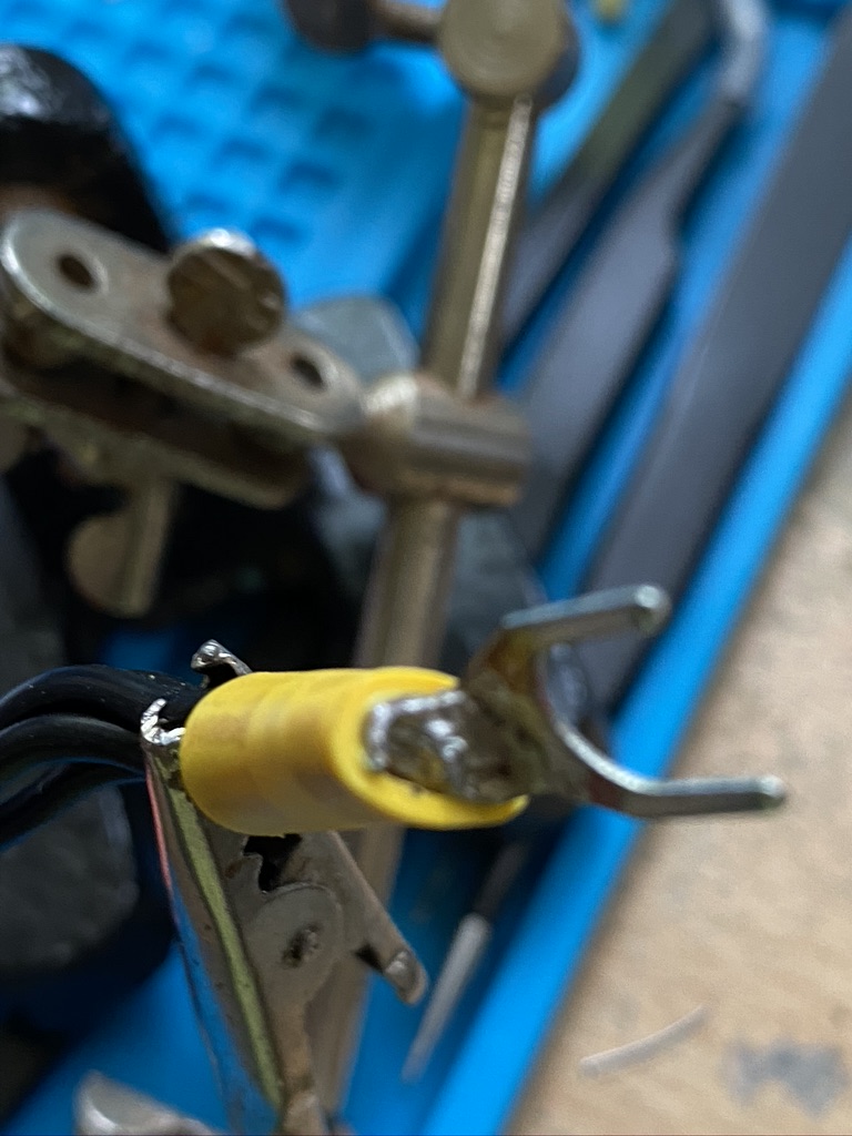
I had already pre-tinned and checked the continuity between socket and wire on the phono socket, so was confident that as long as I was careful I would be able to add the necessary wires to the respective pins.
a good start 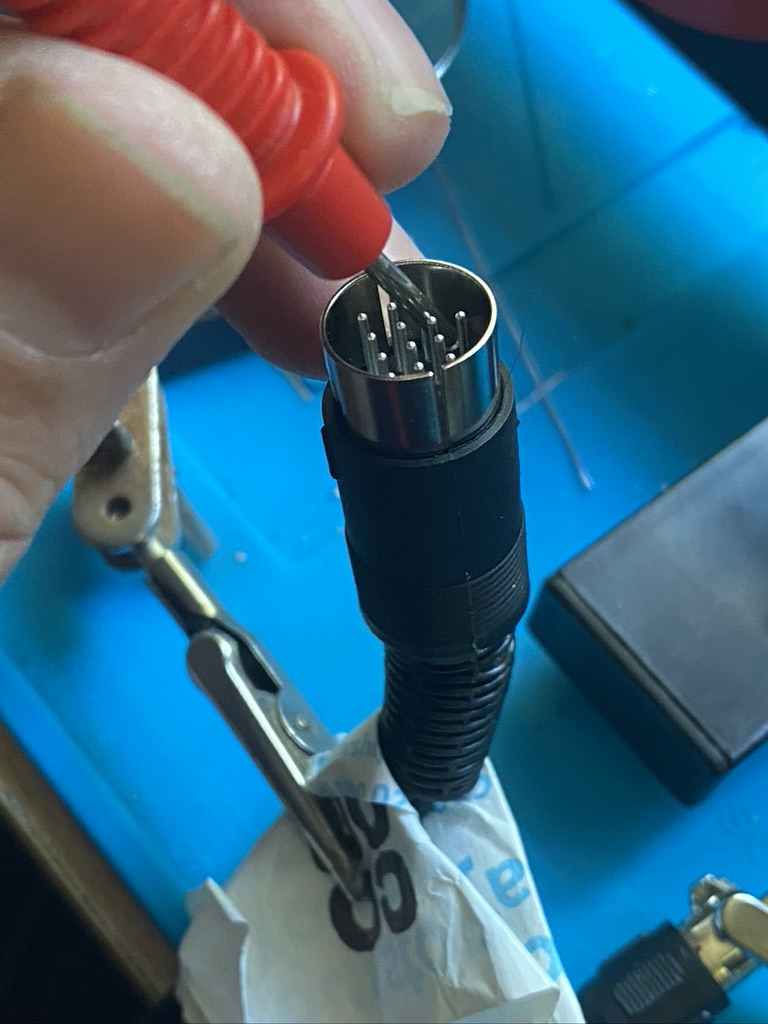
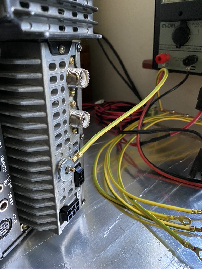
nice on the earth 
crock clip on shielding 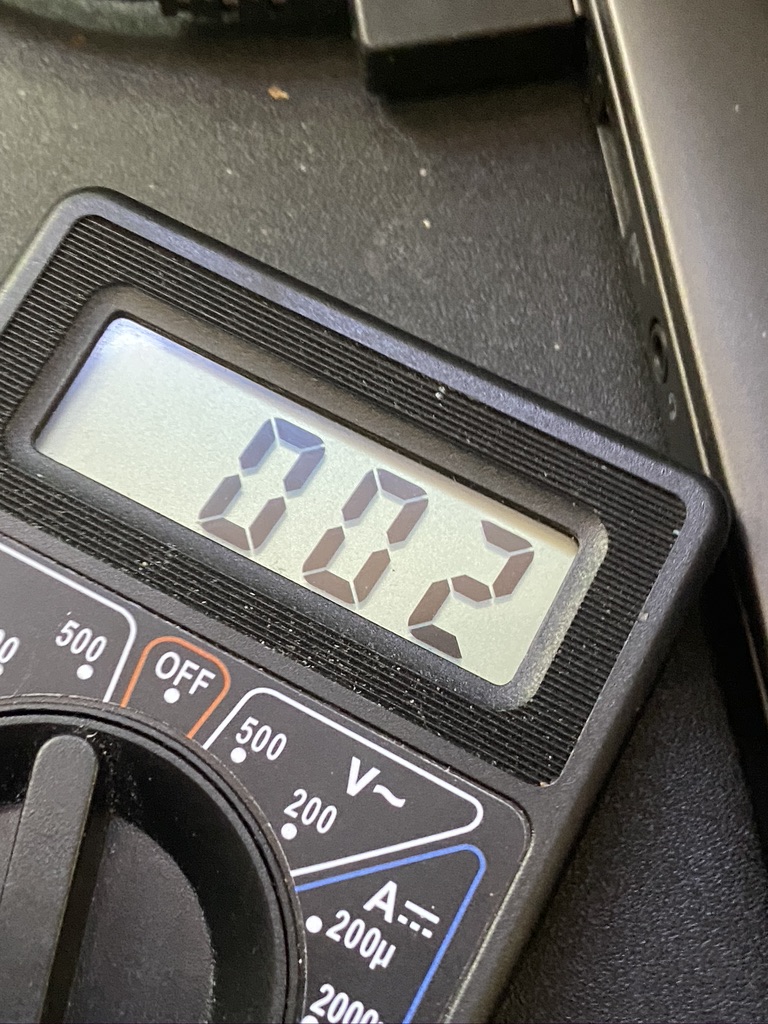
pin 13 result 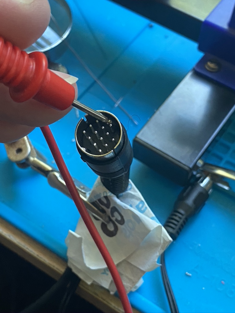
pin 13 checking 
phono live pin 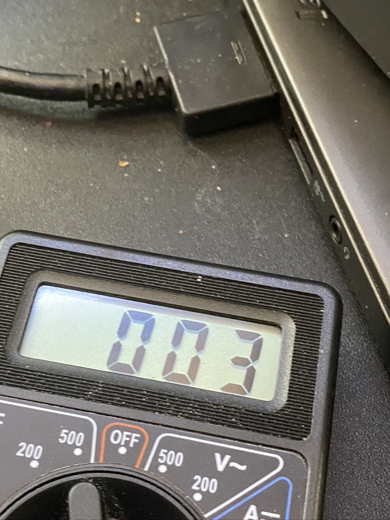
another nice result 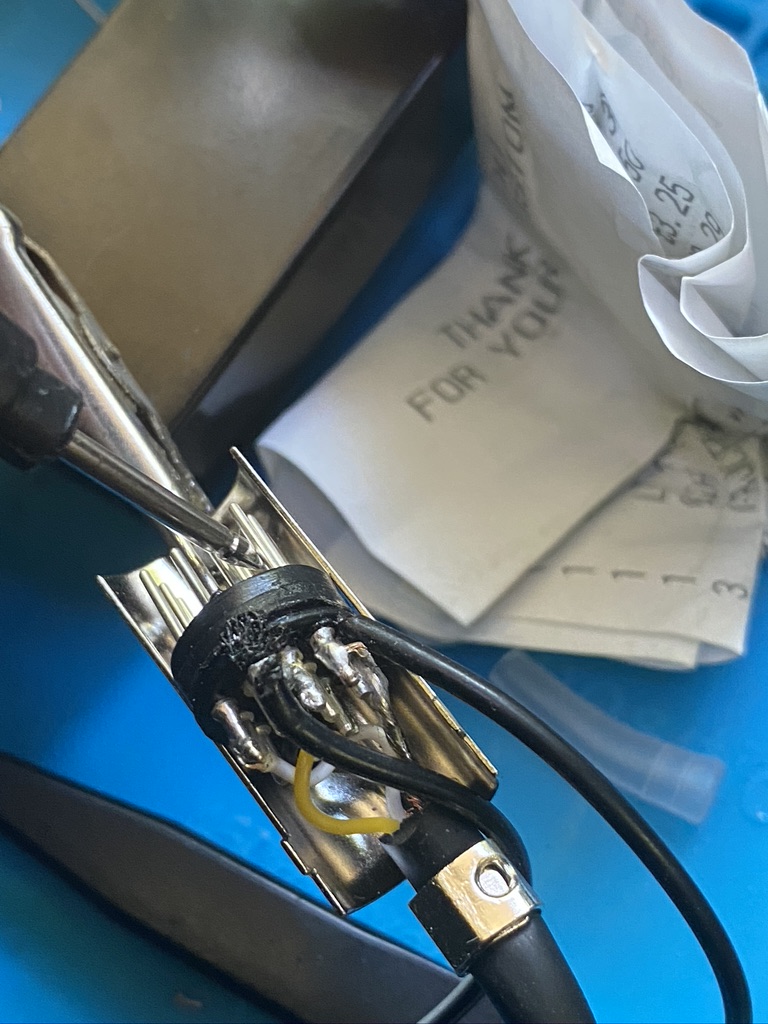
soldering was a challenge 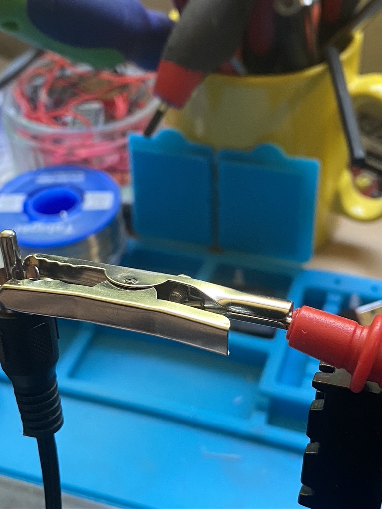
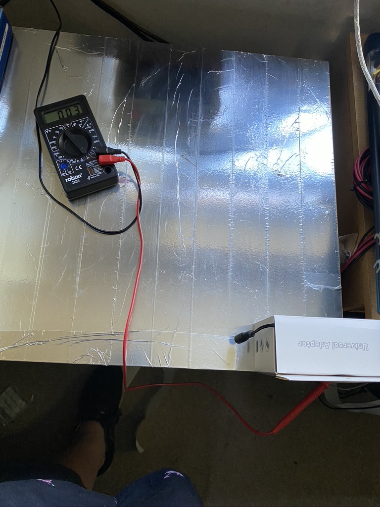
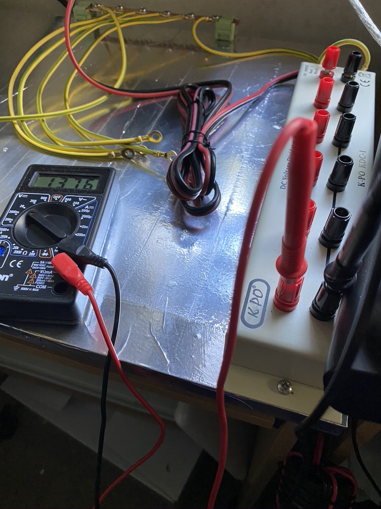
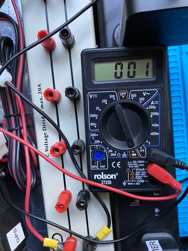
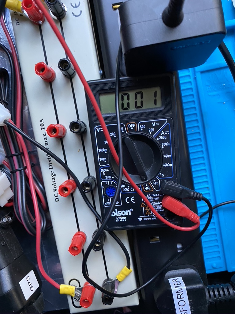
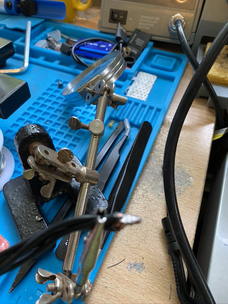
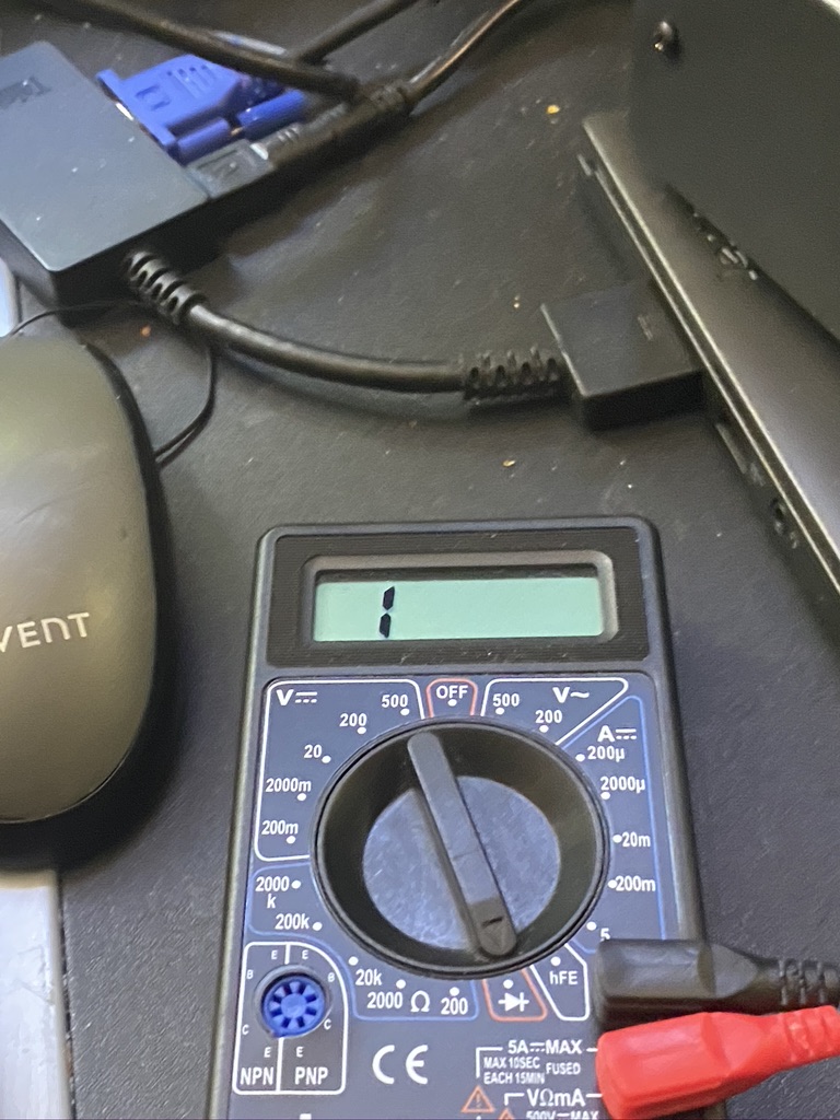
using a croc-clip helped the measurements 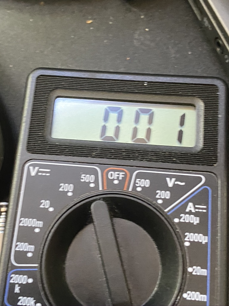
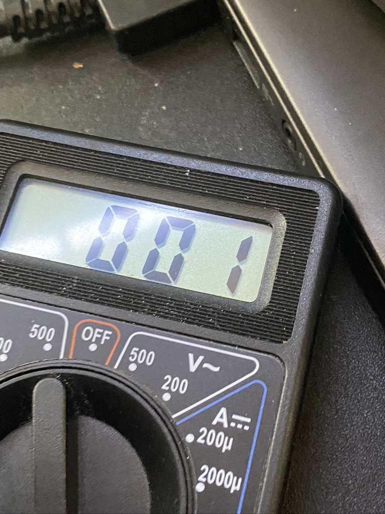
down to 001 with a better fit of testing equipment 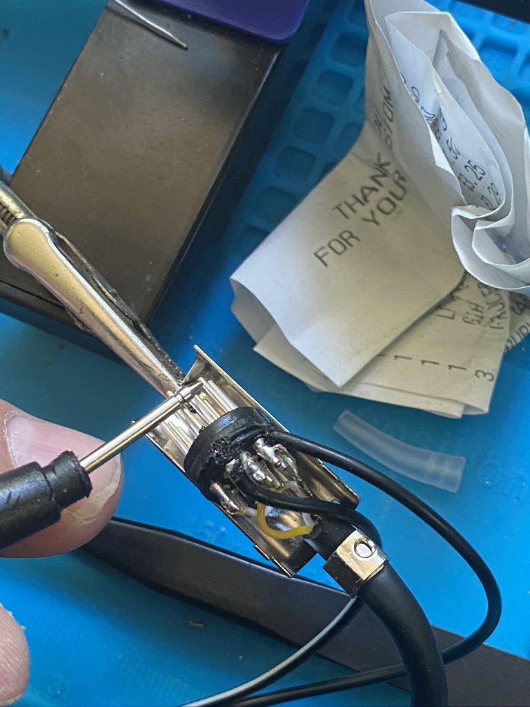
ensuring the pins are level and connected 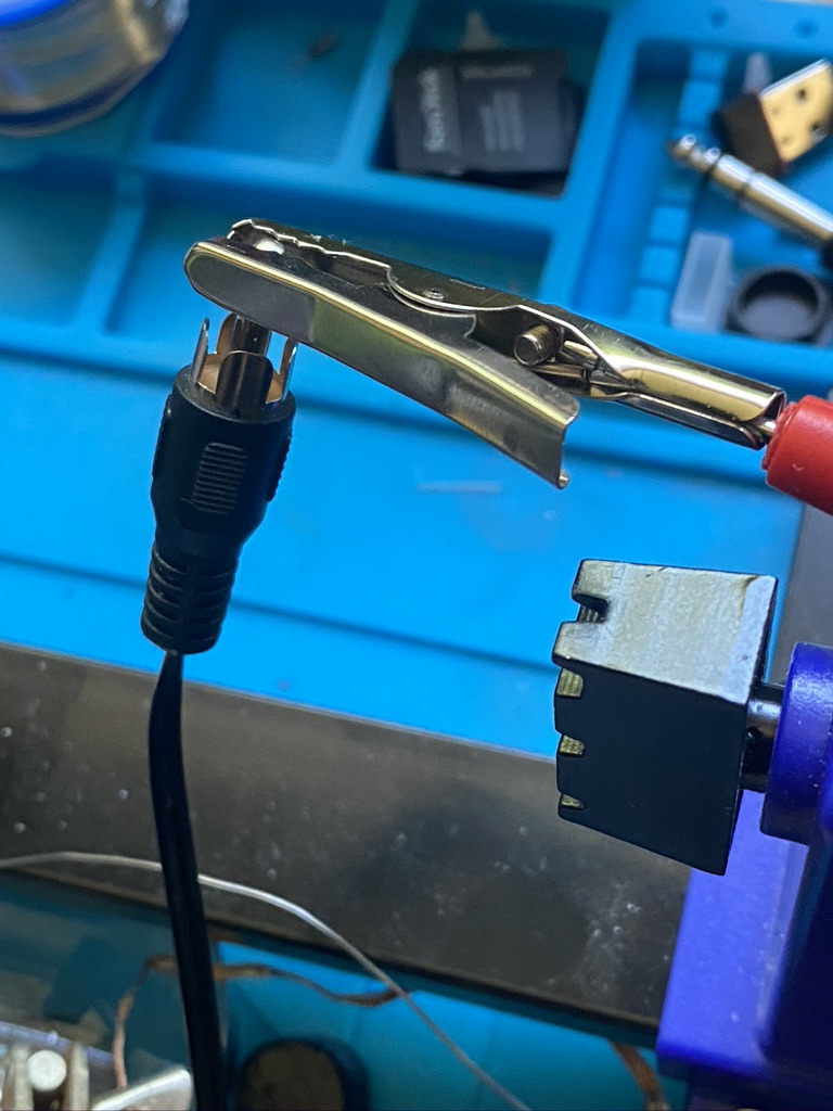
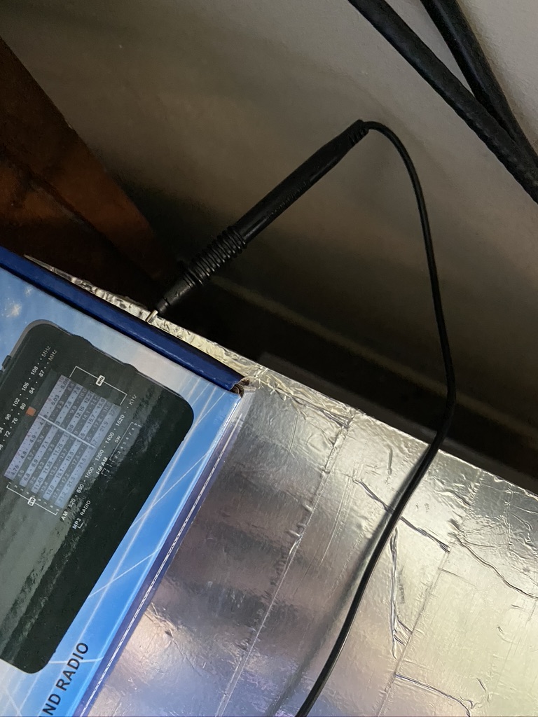
‘live’ socket 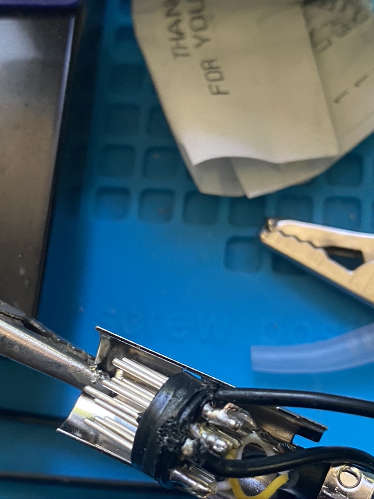
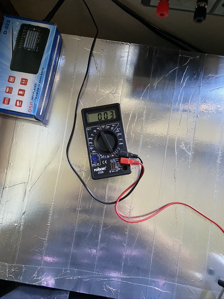
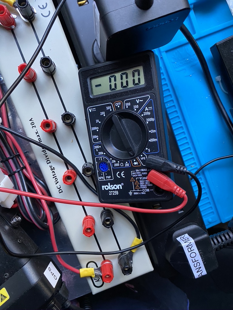
testing for no interference, result!
I dont mind saying that upon putting the shielding on and checking before plugging in that i found that the case (which should be grounded/seperate) ended up being ‘shorted’ and no resistance was shown on the voltmeter. Undeterred I undone the case and carefully applied a small piece of masking tape across the top pins ‘tucking’ between pins to give some isolation. I apologize i didnt take a picture of this. This had the required effect and that when the casing and flexible connector were restored, the isolation between pins had been restored.
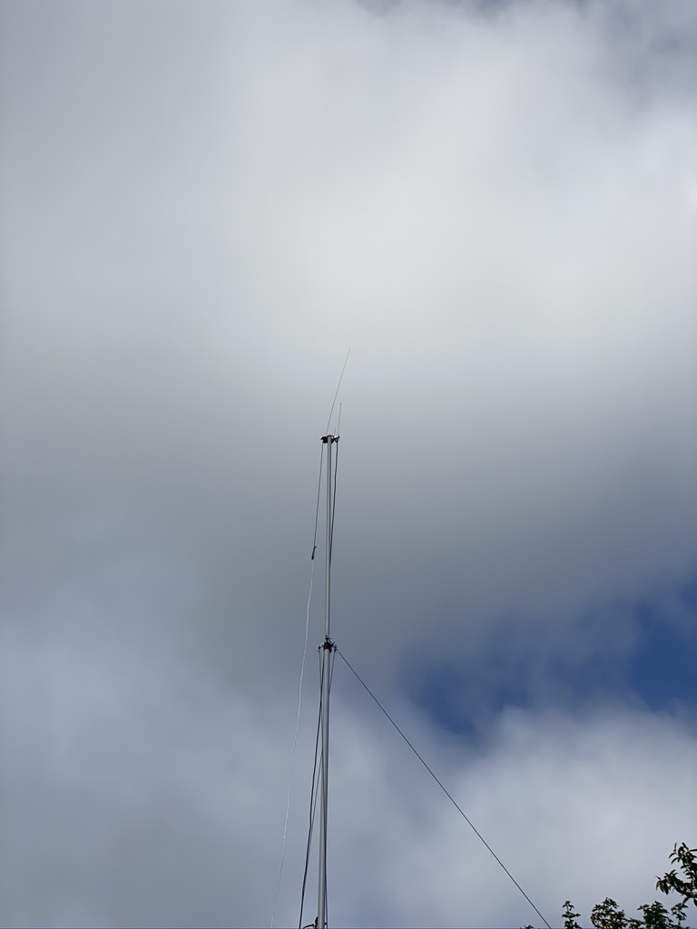
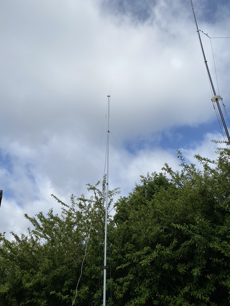
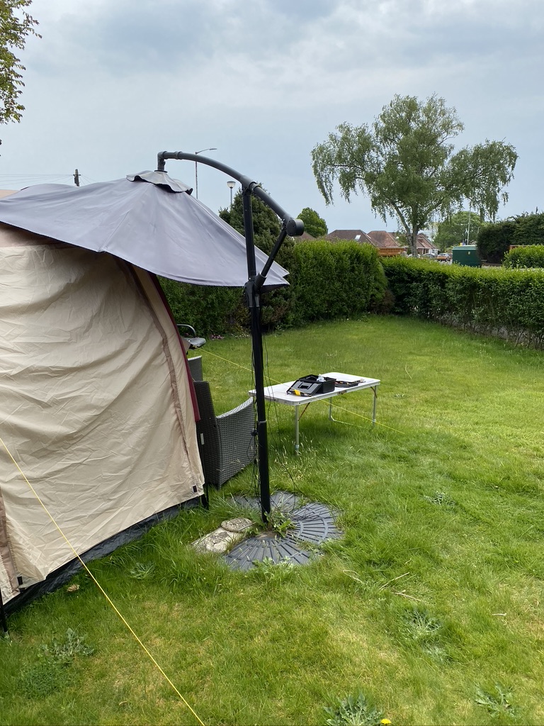
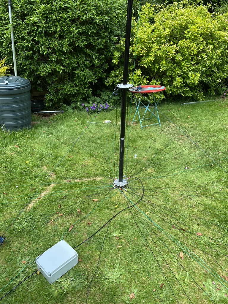
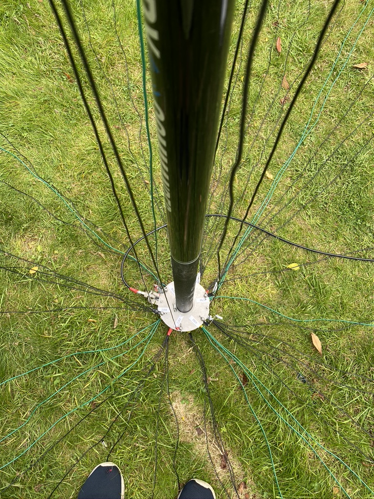
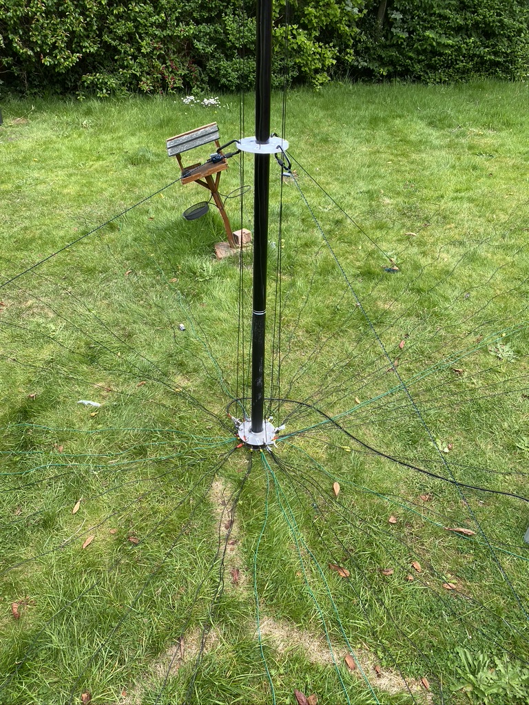
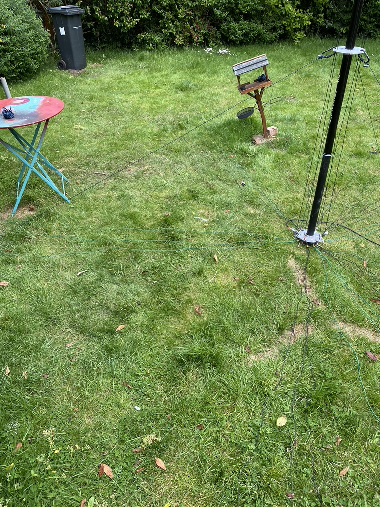
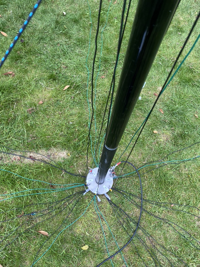
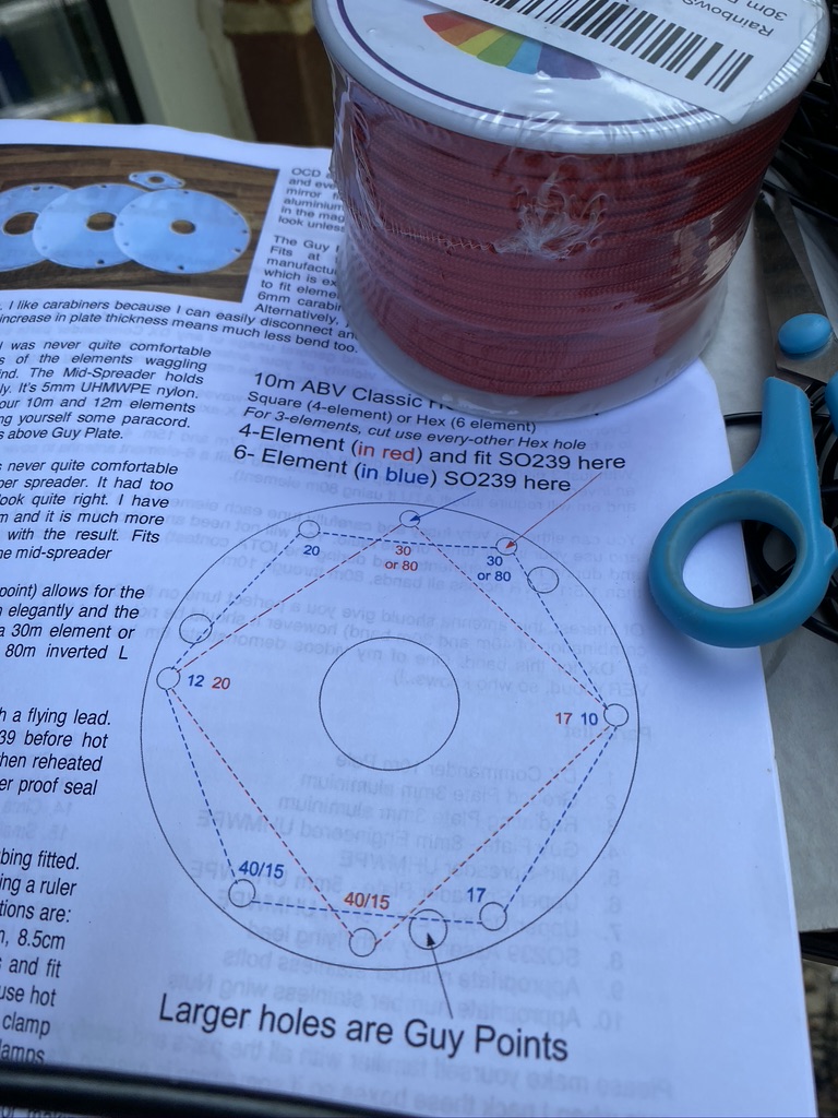
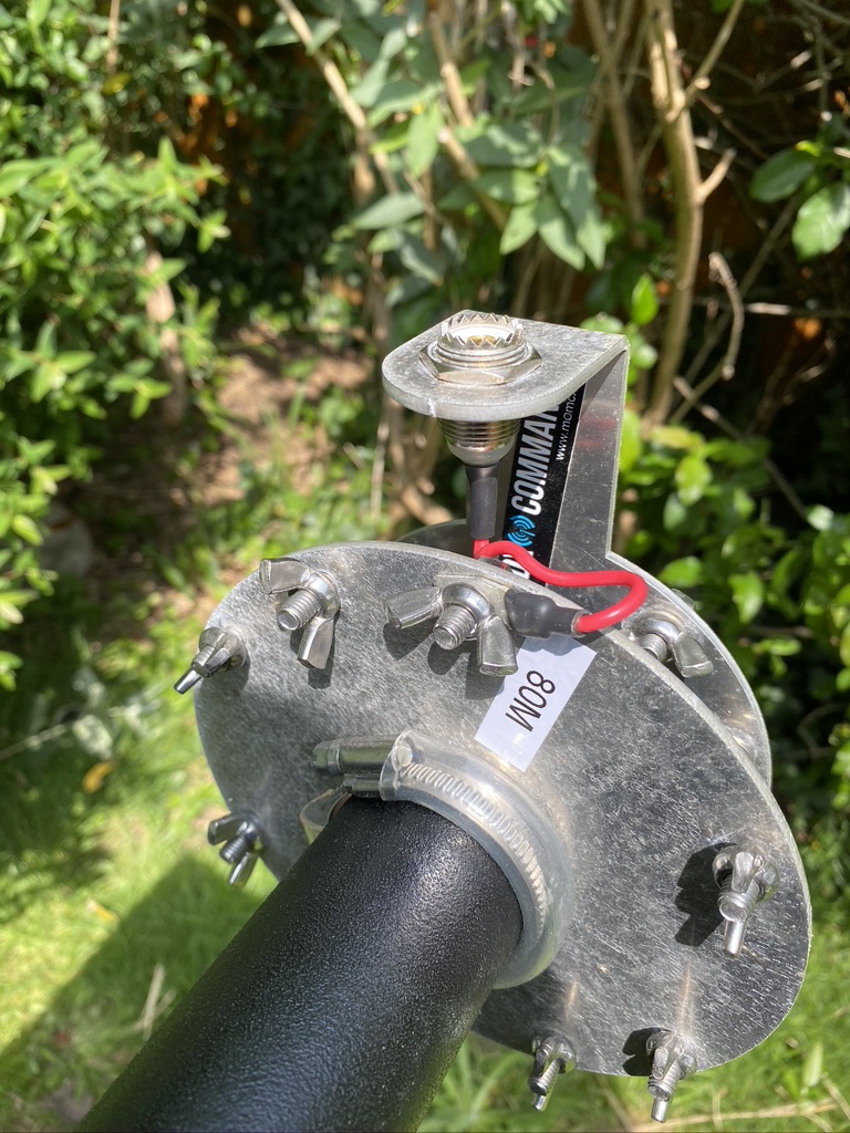
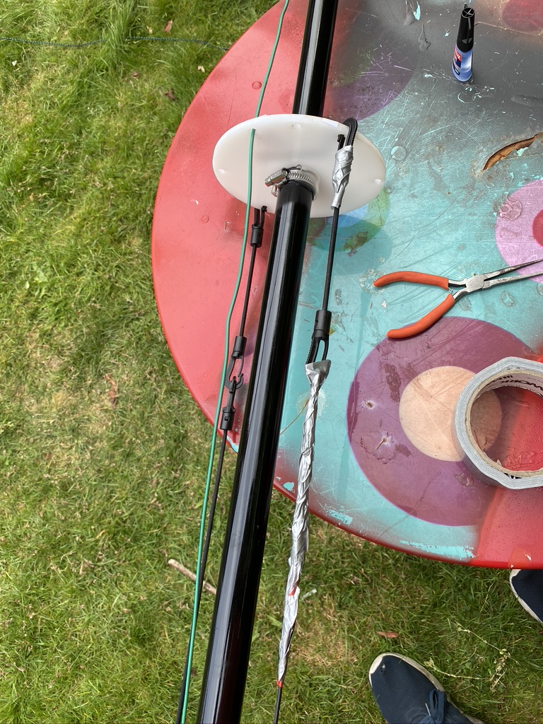
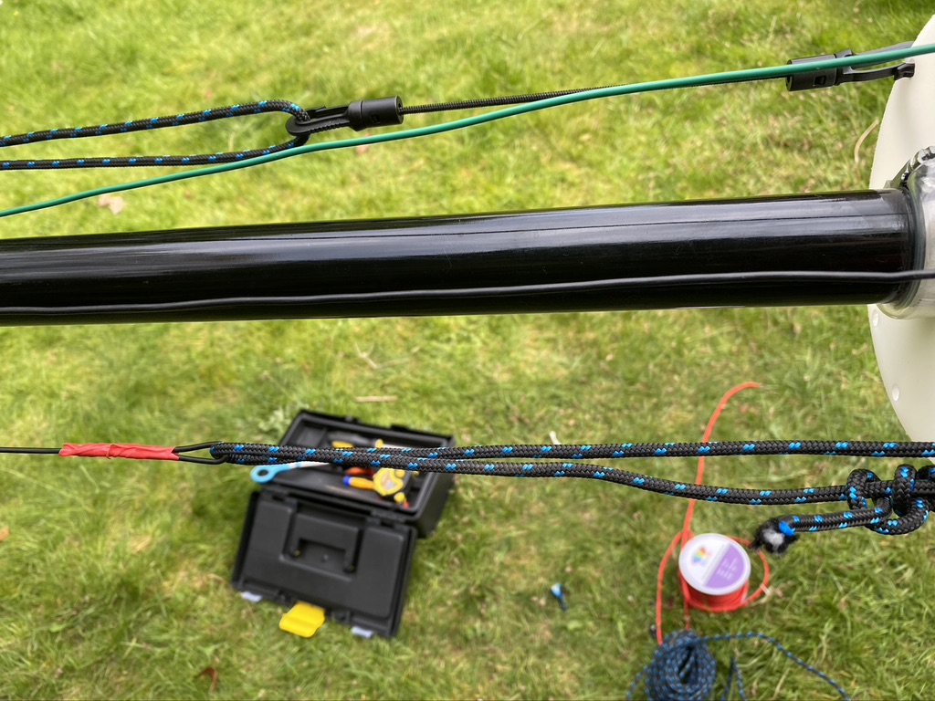
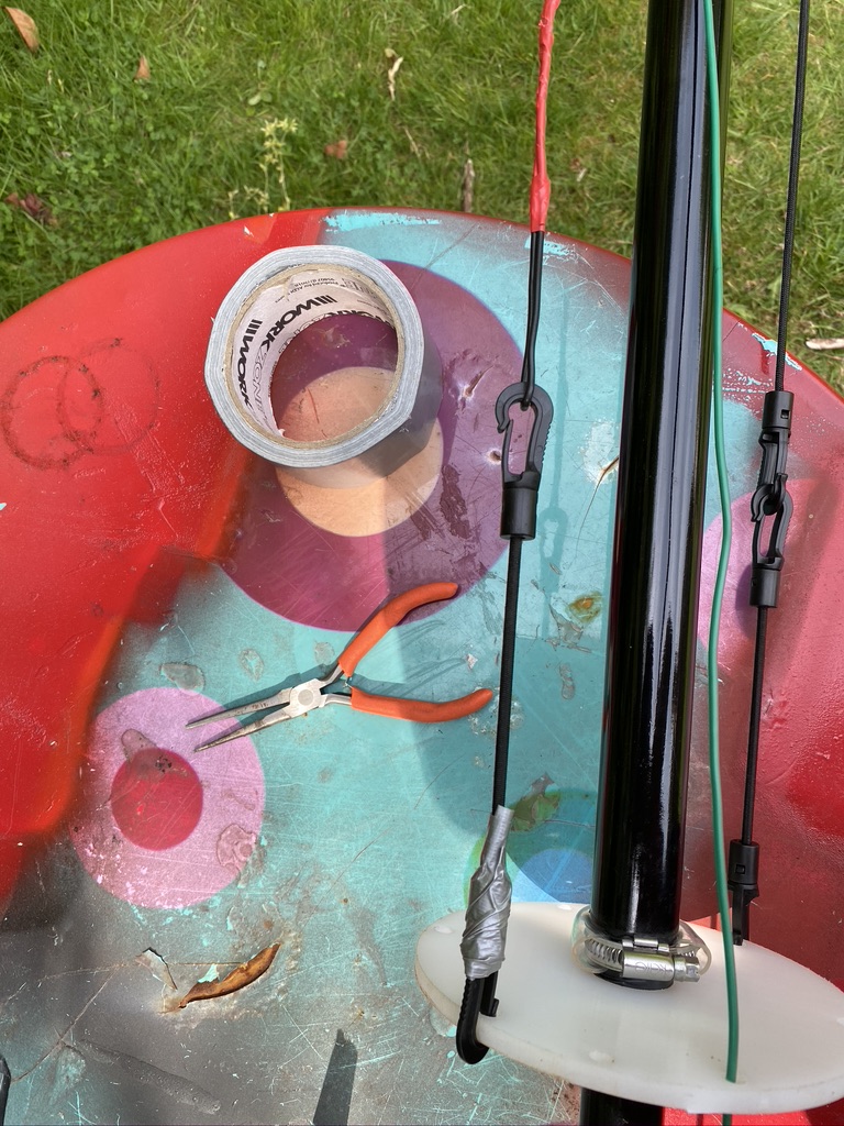
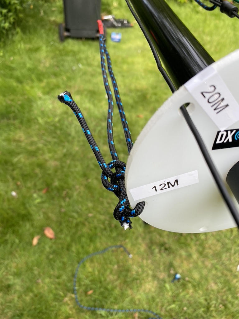
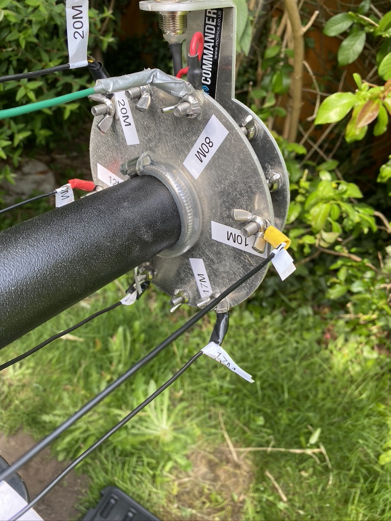
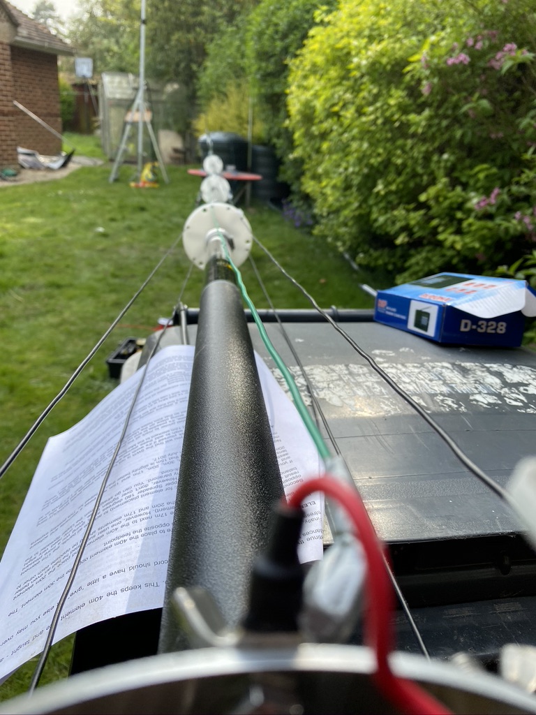
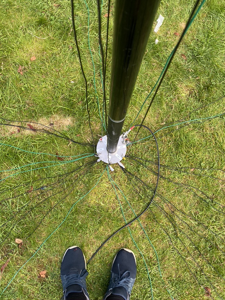
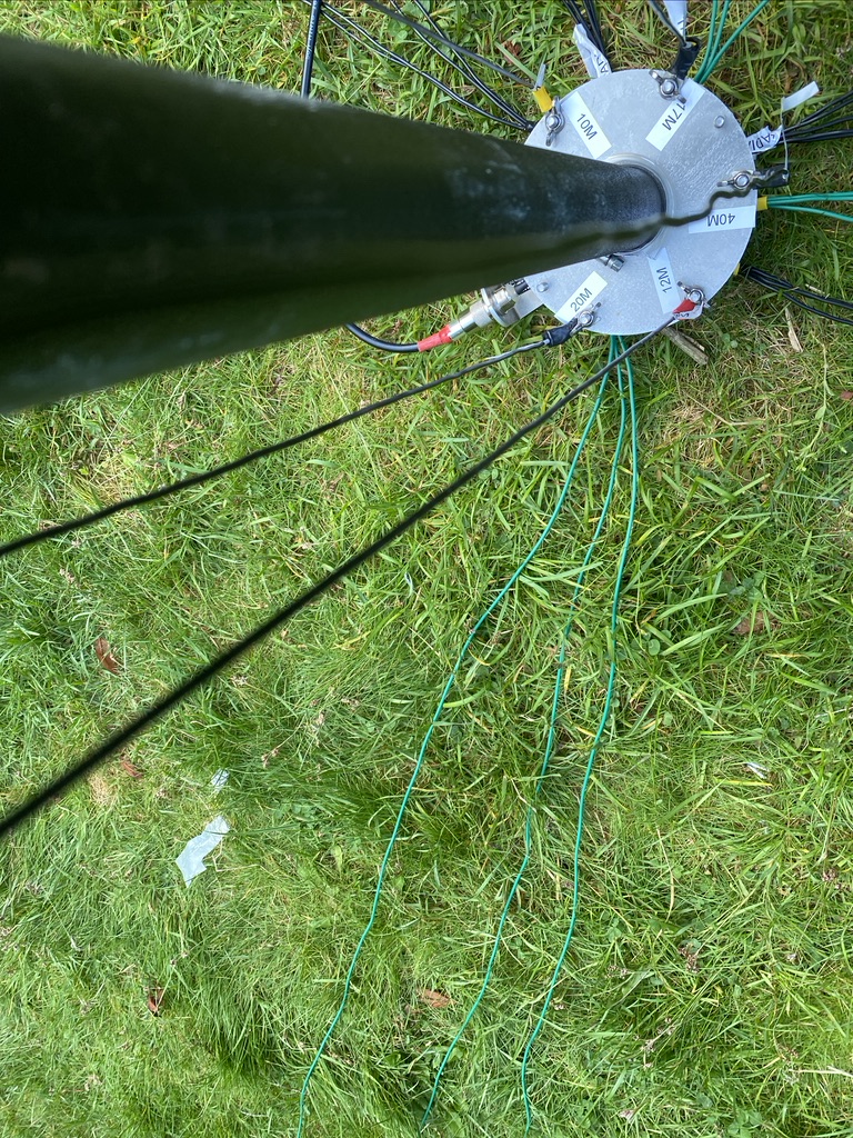
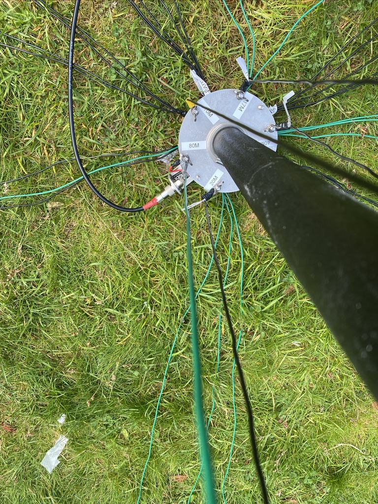
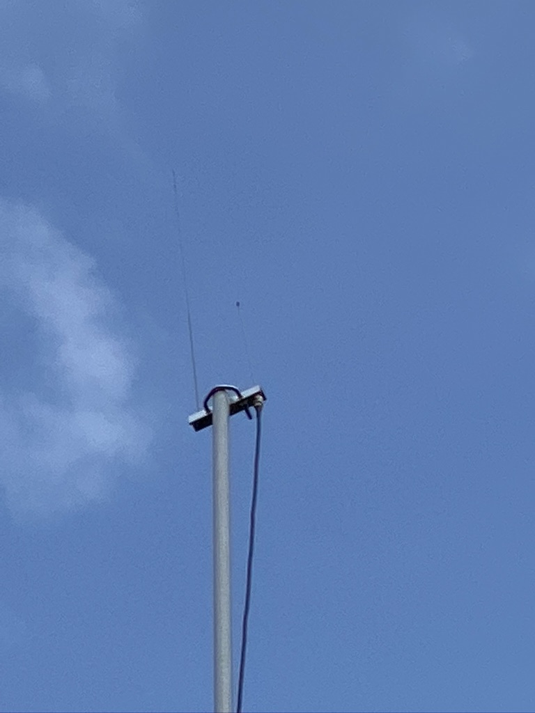
Having completed the cable, the next step is to install an external auxiliary antenna for the MFJ-1028 to match against. I considered several ideas, as in just using a simple end-fed piece of wire, to a range of ‘small’ antennas from Russia that attracted QRM to be used in this way. In the end I decided to get another DX Commander. Whilst I wont totally multi-band this will all 6 elements (in particular 80m requires alot of space) I can setup the 2nd vertical ‘auxiliary’ about 2~3 meters from the ‘transmit’. With this I should be able to ‘phase out’ both any local QRM as well as distant QRM meaning I should not only be able to get out more cleanly, i should also be able to hear and filter those very feint remote signals that currently sit ‘below’ the noise table.
As ever, I will keep posting with my battle with QRM, which I think I am winning one week at a time.