So having got the lab somewhat tidy (pics and a full reveal will come soon !) i can continue working on my 40m Receiver Kit – having wound the toroid and secured it previously, the next step was to add the components and buffer around the tuning circuit.
I would like to point out (maybe again) that one thing that i think is very much missing from this kit is a schematic of the ‘blocks’ of the decoder. At this stage it would be very much helpful to understand what components and how the modules worked together, in particular when we get to the stage of the ‘decoder’.
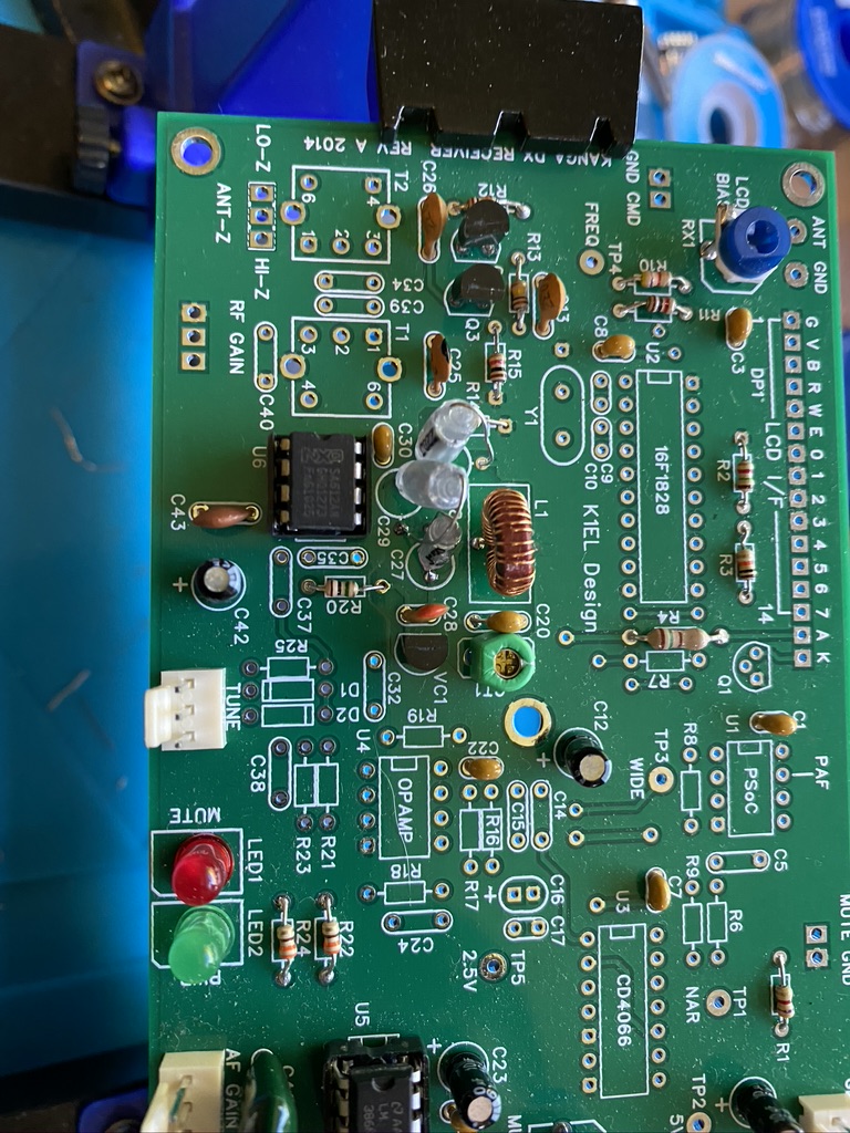
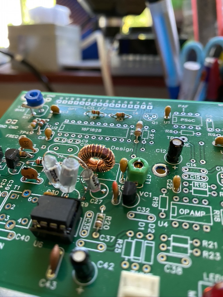
I found getting most components on the ‘push-thru’ was easy enough, the only components which presented a ‘challenge were the NPO and Polystyrene capacitors. As you can see the round circles for C27,C28 and C30 are ’round’ enough when the capactiors are verticle.
On the first attempt i tried the ‘test’ method of using a radio tuned to 7Mhz and got nothing at all. It also didnt help that I didnt know what i would be looking, or in this case listening for. I took a break and came back to it the next day.
Tracing my work I found that i had left a slight dry join on the trimmer. As i have now aquired an oscilliscope I thought it was the perfect use to find the frequency and adjust it.
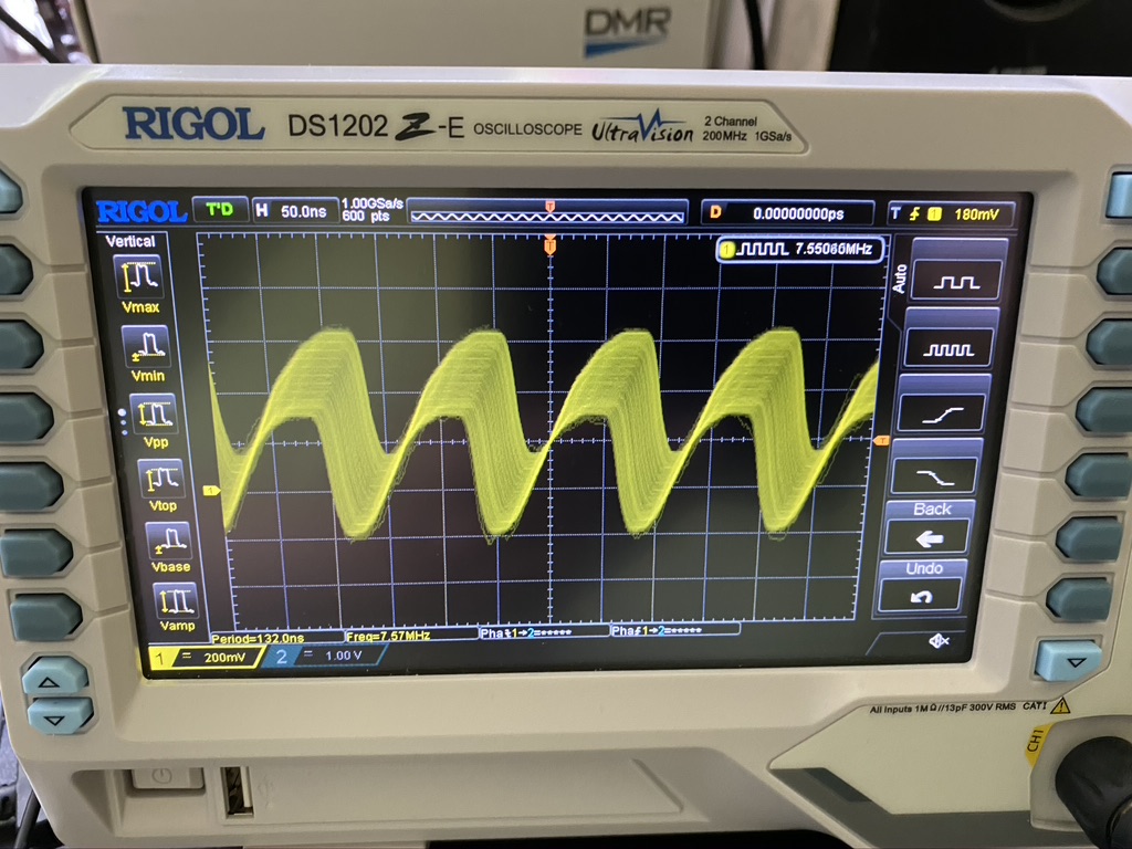
I was so happy to even see a signal on the oscilliscope and also the read on the frequency was not so far out from the 7Mhz. I was lucky enough that the oscilliscope probes come with tuning screwdrivers which are the ‘safe’ type required to tune the trim. I set about tuning to 7Mhz !
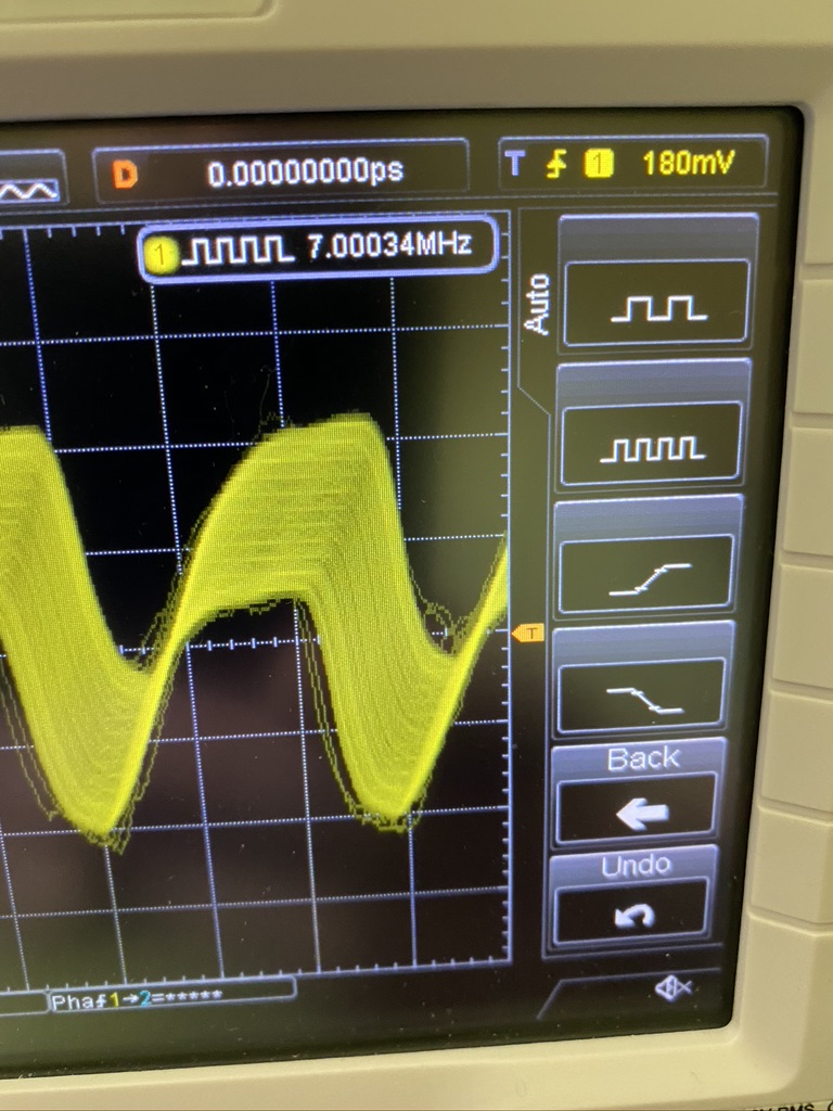
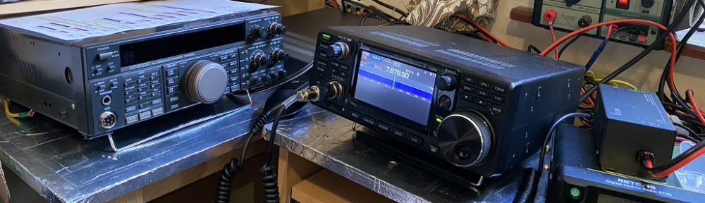
On the scope i could the frequency to read between 6.90nnn and 7.000nn. I thought about trying to see if I could hear anything on my handheld standard (AM) and my transceiver which has more modes (including CW & PSK) as well as specific filters.
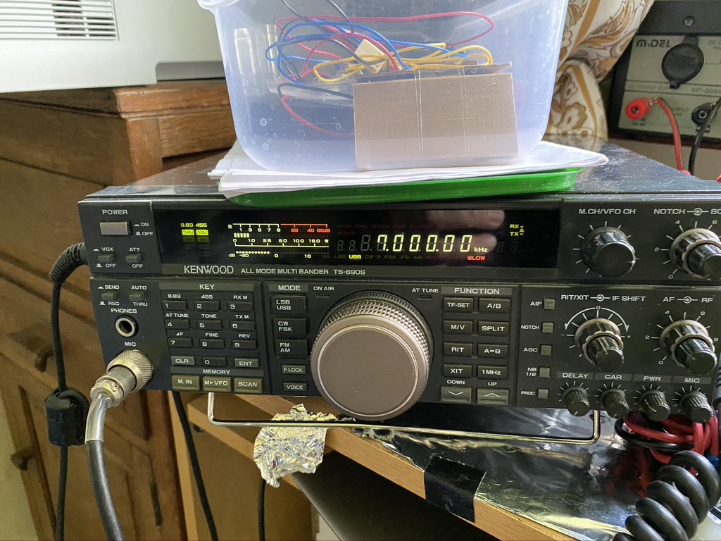
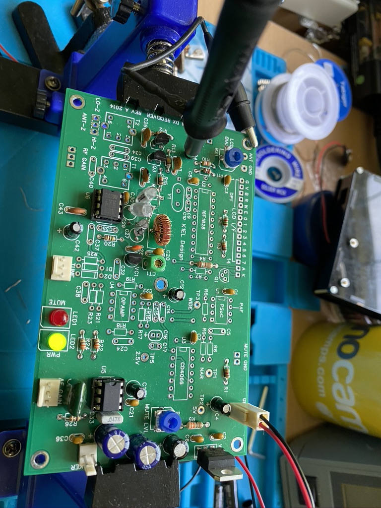
I was very happy to pick up a clear signal on 7Mhz. What was interesting also was that where i have the probe into the VFO / Decoder board, it had turned the ‘wire’ into a small resonant circuit – in fact I could turn my VFO into a theramin ! After 15 minutes of playing wooping noises I set about completing/and tidying the kit up.
I’m really glad that the receiver is going so well – its been all the work I thought it would be but its now very satisifying, esp as its gets more complex.