Icom 9700 – Leo Bodnar Stability kit

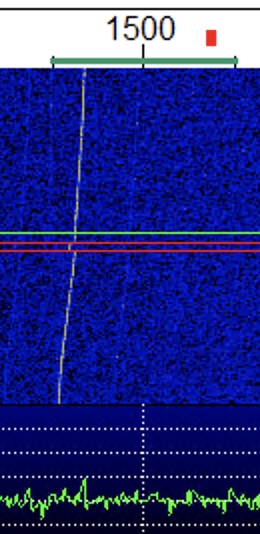
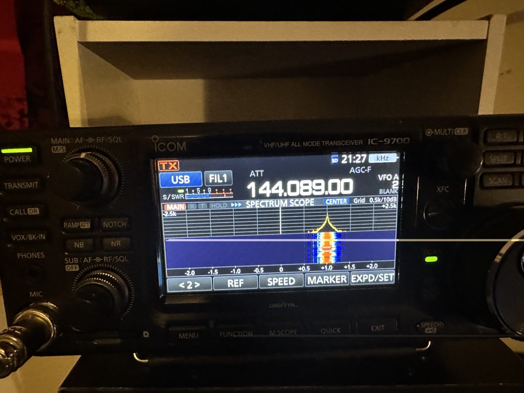
Having being able to do more work on the 9700 and its antennas recently, the ‘drift’ on frequency was getting more apparent, especially so with digital modes with the classic WSPR drift. As I want to do digital modes on the ‘birds’ having a stable frequency would seem like a good prerequisits to fix the drift issue.

WSPR Drift in WSJT-X from the IC9700

I’ve had the injection board for some time, but just never had the desire to open the 9700 until it was really necessary. I have to say that the idea of opening a radio with the price tag the 9700 has to fix an issue does seem somewhat bizzare, but equally I’m glad that leo bodnar solution requires no soldering but stil requires a good amount of care and attention.

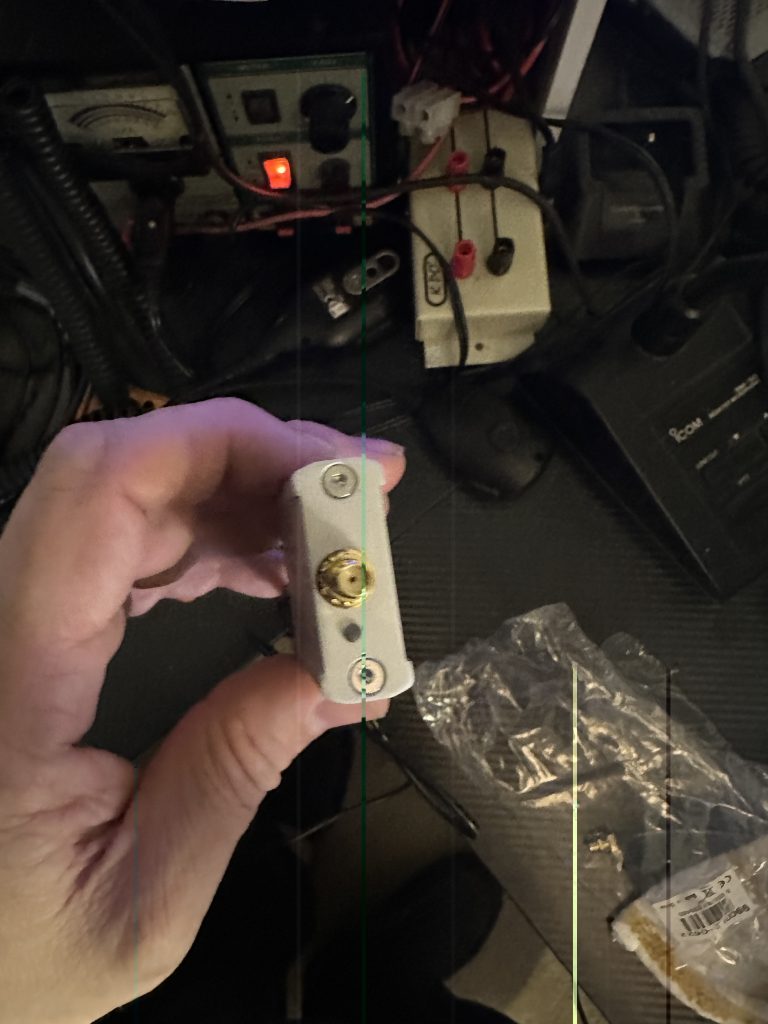
I ordered the mini GPS clock and was pleased to see that it included a GPS Antenna and USB cable, its worth noting that you will need a SMA Cable for going between the GPS clock and the radio itself, thankfully I had several good length ones here in the shack thanks to my work on the chipwhispherer capture board.

My reference video, which is also linked from the Leo Bodnar site, is the ‘gps lock you icom ic-9700’, I watched this several times before even opening the radio.

The most excellent how-to video on fitting and tuning the GPS lock on the ic-9700

Having watched the video one last time, I set about opening the 9700.

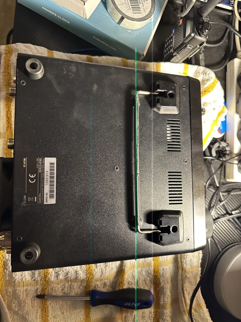
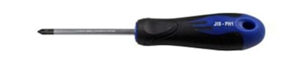
I waited an extra day before opening the radio as I dont have any JIS screwdrivers and didnt want to wreck the screws on the 9700. I found a nice set for £12 on Amazon that done the job nicely, tho some screws may of been ‘locked’ in, a good strong ‘tap’ of the screwdriver ensured the screws came out easily.

JIS2 screwdriver for exterior screws on IC9700 base

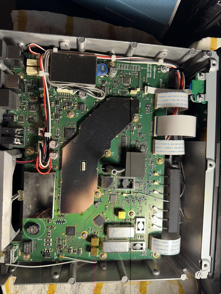
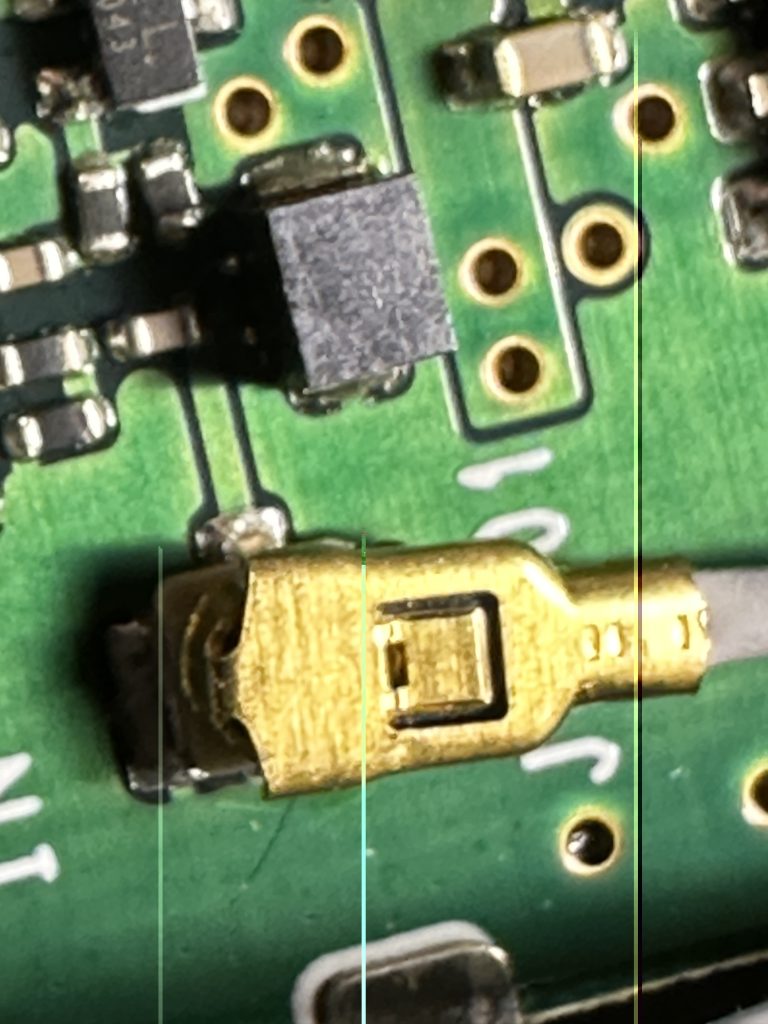
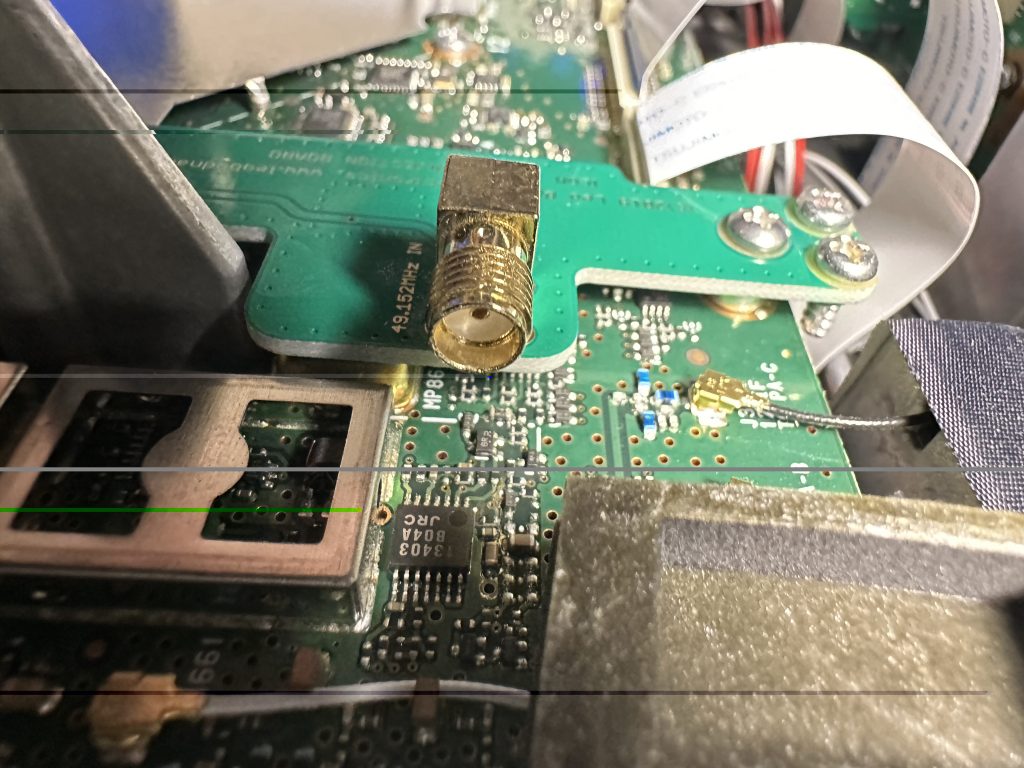
Having got the case open, i then set about removing the thermal protector and existing wire. I was trepidatious about removing the connector, its very small with alot of components around it, with a little ‘wiggle’ it was removed. I used a bike-kit socket set to remove the connector from the chassis and stored in the board box.

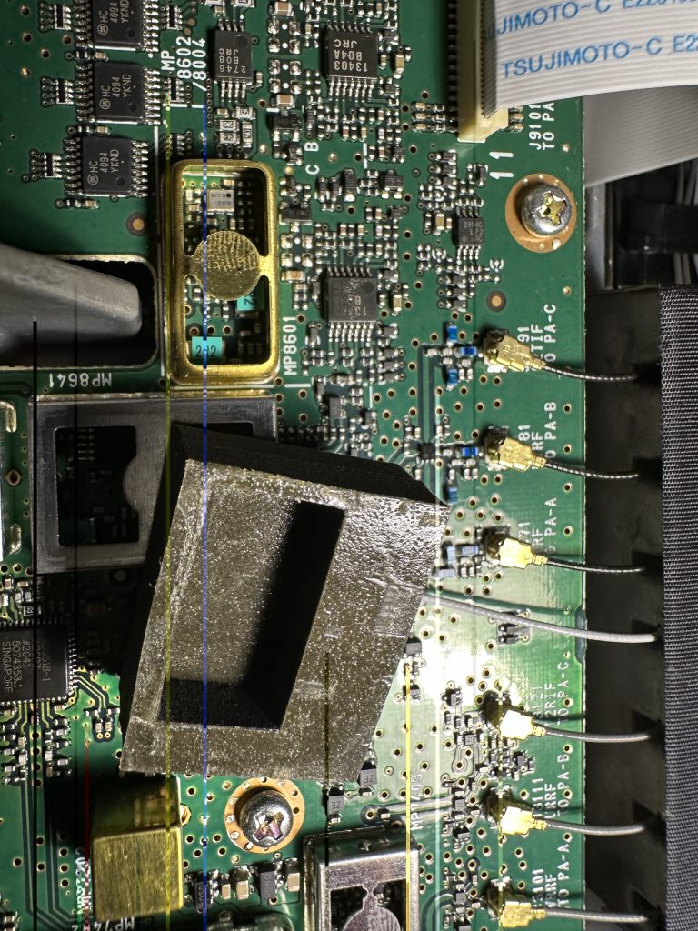
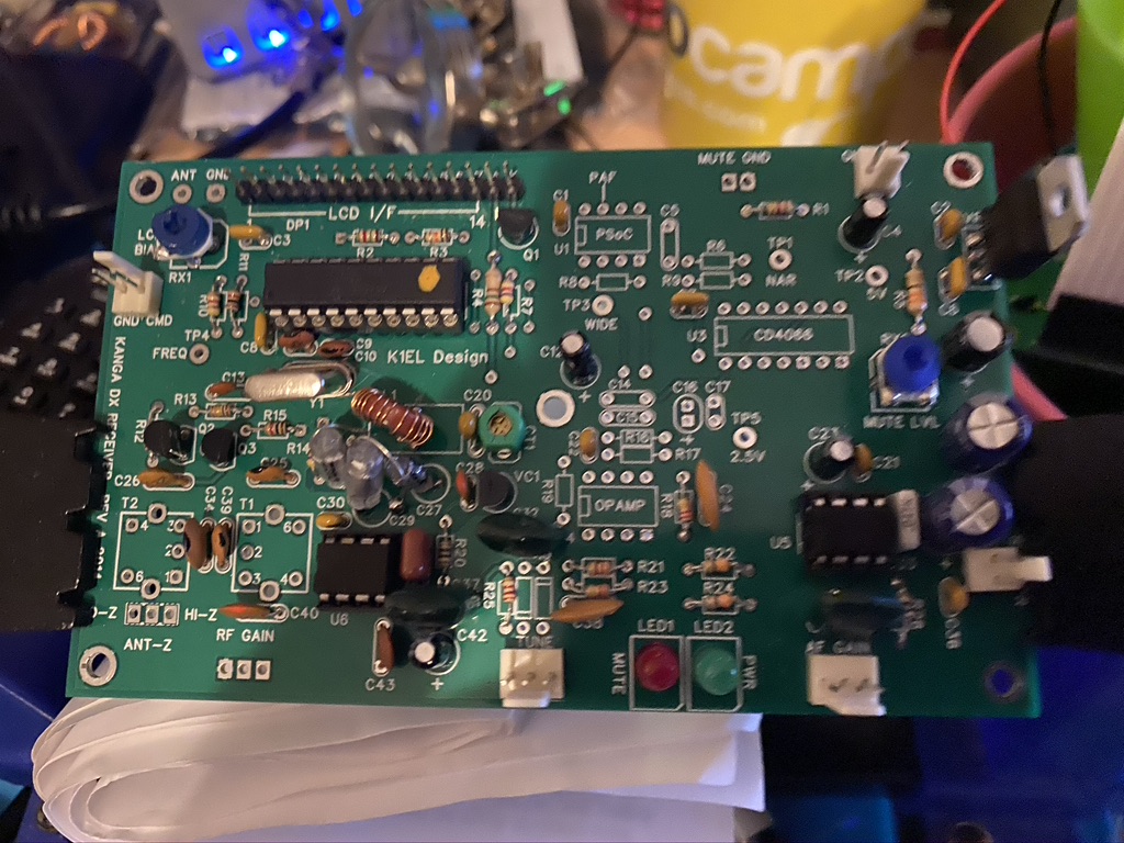
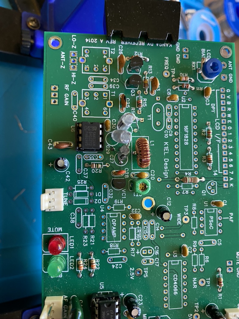
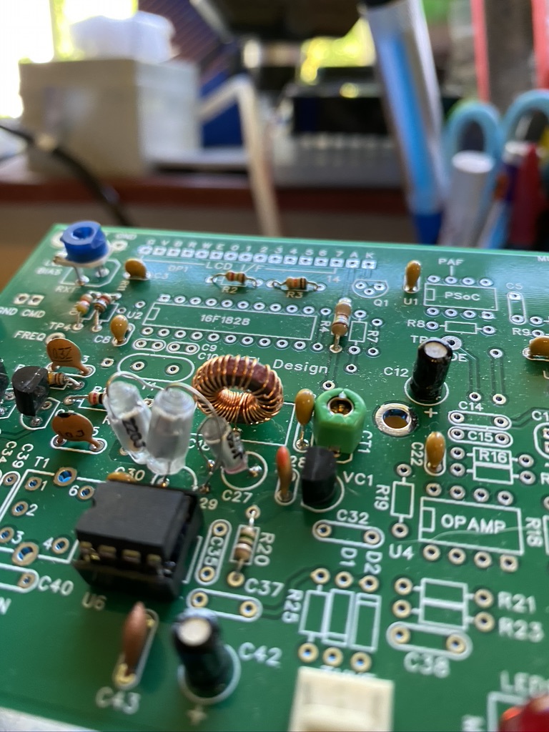
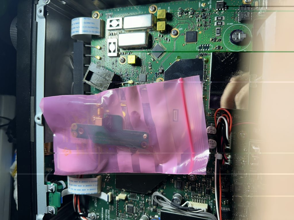
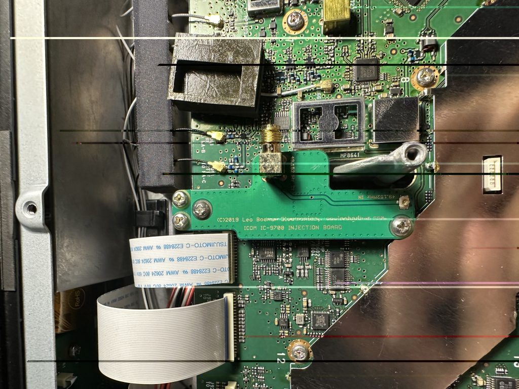
I then went about fitting the board, i first sized up exactly where it would go and what screws to use, there are two pairs in the box, I went with the longers set which done the job well of holding the injection board to existing screw holes. I made a visual inspection with my phone to make sure the board was fitted correctly and should work correctly.

Once I had fitted the board, I put the power back and turned on just to ensure nothing had shorted/issues, then put the bottom case back on. I found getting the power connector on and off the 9700 really fiddly ! hopefully I wont have to remove it again ! 🙂

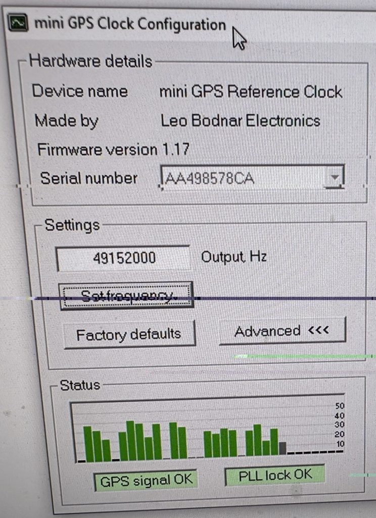
I then installed the software on the computer I use for the ic9700 that has PCSAT32 and HRD installed on it. I didnt see any Linux software for doing this, so was at advantage running Windows in this instance. I liked the GPS Clock had a blinking LED on it as well. I hooked up the external antenna and was soon picking up the GPS signal without issue.

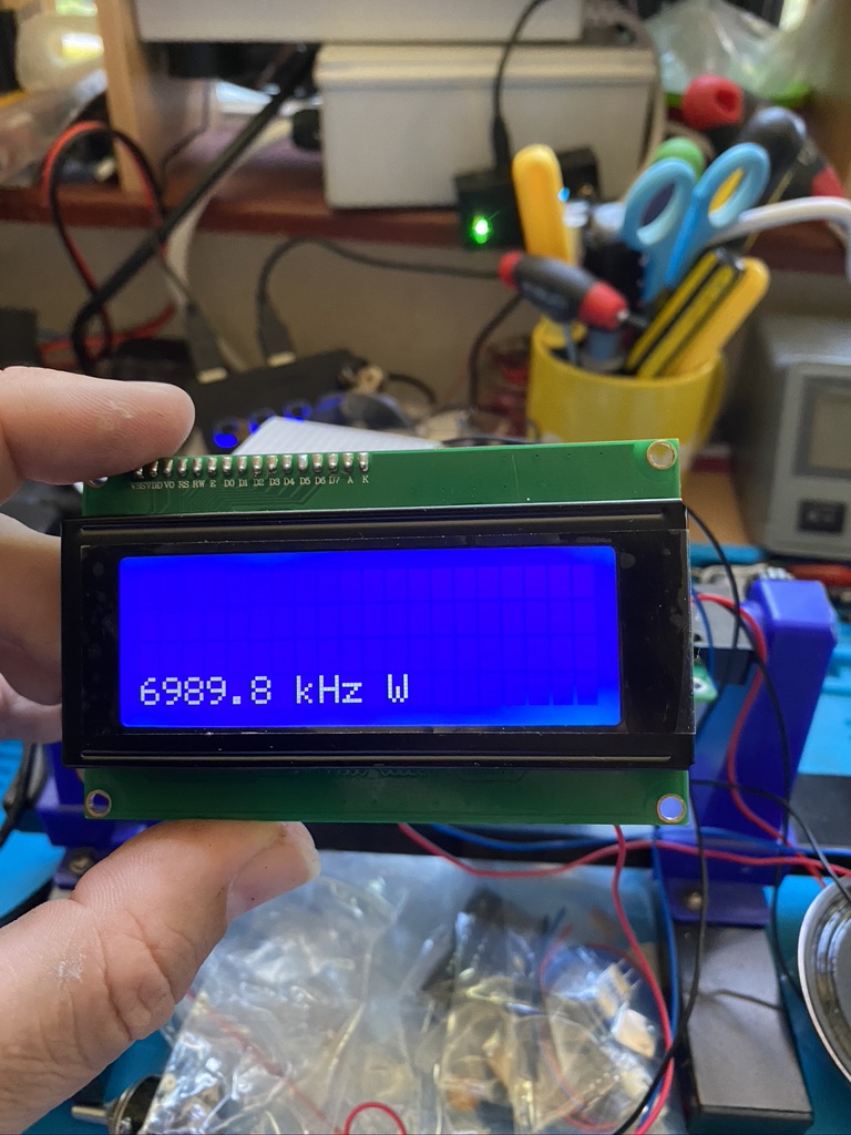
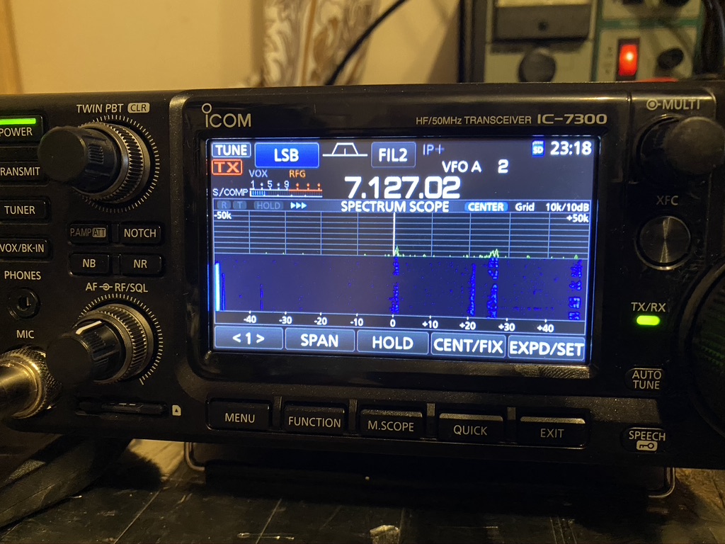
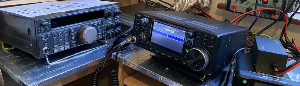
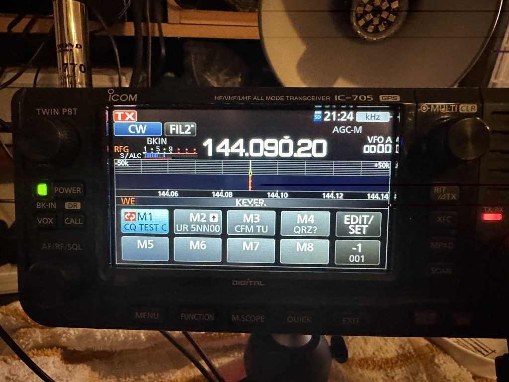
For signal generation I setup my IC-705 with a 2m/70cm whip antenna, and set the power output to 0, i was able to use the morse mode to generate a repeated CQ TEST 2E0FWE as my frequency marker, I could then use this to ensure the injection board was working correctly.

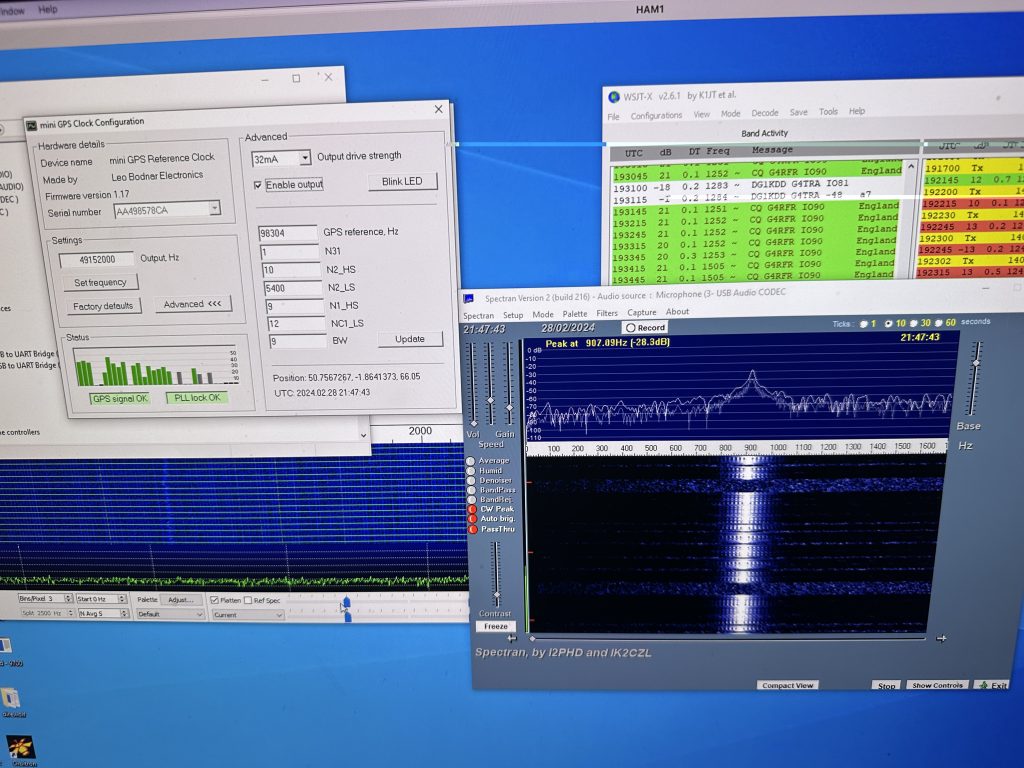
I was really impressed of how well the frequency locked and the stability of it. It only took me a couple of hours tops to watch the videos and fit everything to have a radio which will work well on digital modes.

Hopefully you will see more videos of me using the digital modes on the ‘birds’ soon, but am glad the radio is up and running !

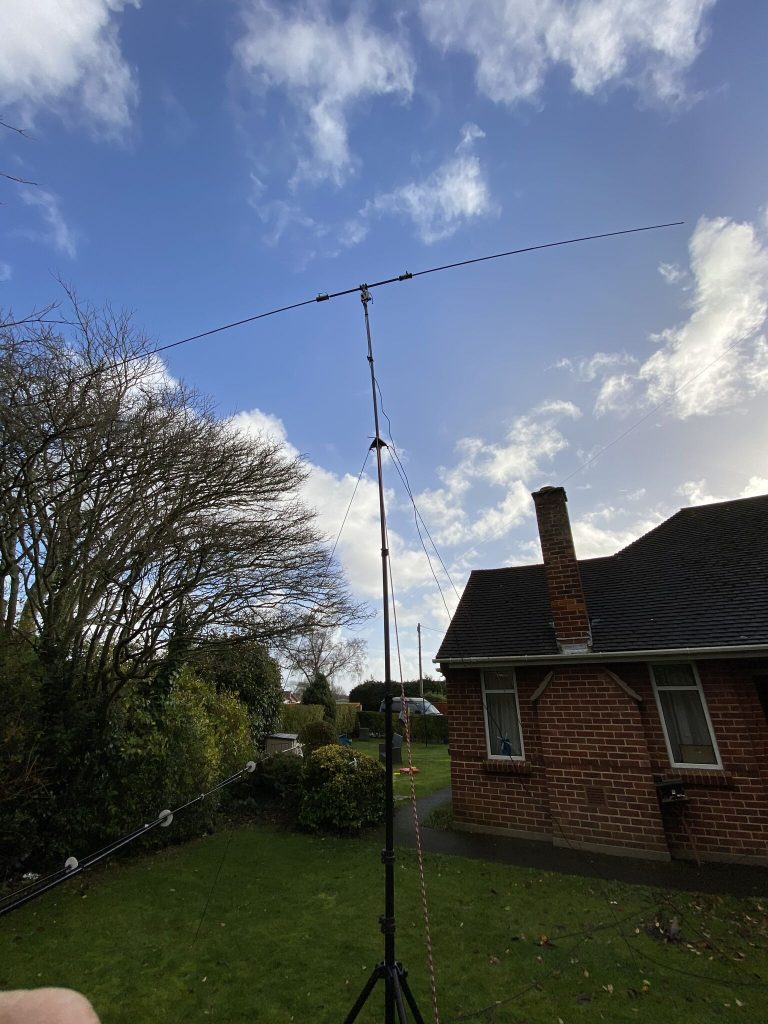
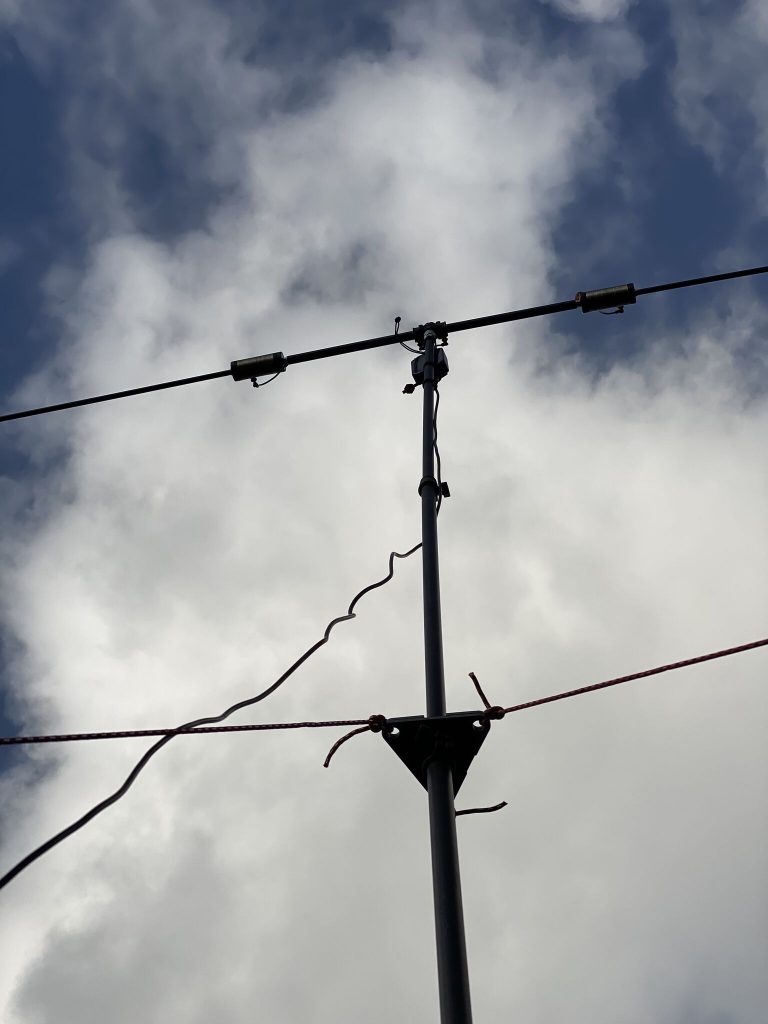
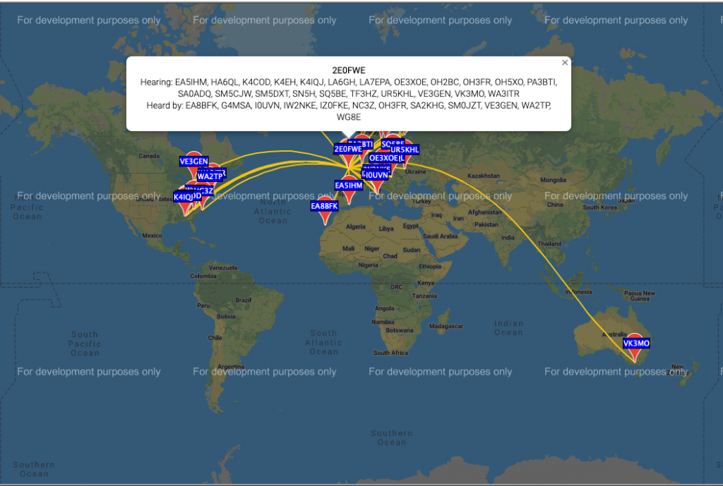
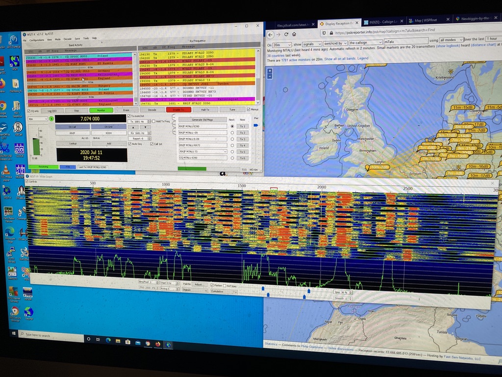
When I’m working during the day, I’m using WSPR to test the antenna and even tho its an eggbeater its doing great with WSPR.

WSPR on 2M

73 2E0FWE

A day of masts.. but 20M fun !

AM450 woes

So i started the day out on really wanting to get my MFJ receive only loop antenna up. I have used it before, but always slightly too low. The mast I purchased to support this is the DIAMOND AM 450, it is designed to hold light antennas such as the MFJ-1886.

As you can see in this video

just twist – yeah twist my a**e

When out with it, i guyed it and twist-locked the mast, but it always came slipping down, most the very top and the 3rd section from the top. I took the antenna down and brought it in for the evening, giving the mast a good clean/dry and seeing if i could get each section to lock in the comfort of my hamshack.

I did have some limited progress but still felt the 3rd section was not tight enough, the others were so tight, they really was an effort to unlock them.

I went out the following day, but again the mast slipped. I stood there trying to tighten each section, for untold time, but it just didnt grip, at all. I was clearly wasting my time with this mast. So if you want my opinion, DONT get the AM450, its dreadful mast with poor locking sections. All my other masts have some form of ‘lock’ or ‘locking screw’ and work perfectly.

Buddipole 20M

So whilst i am enjoying just how good the little mag-mount whip works on 20M with the IC705, i do have a proper, and pretty well equipped, buddipole setup. My problem, and here the blame lays soley with me, is that when ever I use the buddipole a part of it breaks, or gets damaged. I am pleased to say todays work showed that my patience and method have improved and no damage to the buddipole occured (so far..)

I want to put this here as a warning for anyone that buys the buddipole *ALWAYS GUY YOUR MAST* and not just ‘at the end’ when its going up, when ever you are working on it/near it, guy it, you need to concentrate on getting the SWR down and doing the loading on the coils correctly, bumping the mast so it falls over is probably going to hurt you and your wallet when the expensive ‘whip’ antennas snap from the copper screw-ends.

You do not want to rush a buddipole build – much like any other antenna, but there is more to do with a buddipole, hence why I’m always a little bit reluctant to get it out. Compared to a dipole or a random end fed, there is a substantial amount of work (arrange parts, put parts on, tune antenna – reguy for elevation, measure SWR, bring down, SWR..)

But that said I’m very happy with the gain I’m getting off the buddipole dipole, sure it could jus tbe the conditions, but the antenna is really pulling in the signals. I’m putting out 10mW on WSPR. Just checkout the reports.

WSPR Report on 20m with .1W

On FT8 the SWR was over 3 on 5W of power, but I’m hoping the kit I’m building will help with that !

It will probably take me a few hours over a couple of days to do all the necessary winding and soldering, but the ATU gets impressive results (when built correctly !)

ATU-100 demo

I’ve ordered some tools (didnt fancy cutting a fence post with a small wood cutter) which will come in useful around the house.

Stay safe and 73 !

Alan / 2E0FWE

40m propagation / Kanga Kit / Intermediate Exam news !

Its been a lovely warm weekend down in Dorset, and that seems to have affected the propagation. I had a great time on FT8 and JS8 Call, reaching amazing distances and really good signals being put out and received. I had many logged contacts and good signal reports.

40m got *busy*

By the evening 40M got as busy as I have *ever* seen it, as shown in the picture above i switched about the bands and was making contacts on 15M as well, it was the best conditions I had seen so far !

Resume work on the Kanga Kit !

After a break of sometime, I have resumed work on my Kanga Kit – this fits in with the news I’m putting below, but I have a big thanks to John Clements who helped me fix a fault with the kit I was unable to locate. John found the issue (soldered pin-header together – hidden by the plastic) and returned the now working Kanga kit to me ! I have resumed work and am taking my time – I’ve completed more work on the resistors and capacitors on the Active BPF.

kanga kit with added capacitors for BPF stage

I’m taking my time, esp as the board is now quite ‘busy’ – the next step is to add diodes and IC’s. Its really close to completing the build, but taking my time to ensure no more mistakes !

RSGB Announce Intermediate Exams on-line !

As shown in the picture above from the RSGB site Intermediate exams will be available from the 13th ! (in 8 minutes time as of writing) i’m very excited that i will be able to book my exam and get use more wattage but also gain more insight to a very interesting hobby as I continue my amateur radio development.

Whilst the practial assessment is waived currently, i will continue to build my Kanga Kit, so if the issue did come up of what Kit I did build, this is well recorded and documented.

To close the evening off I had a splendid evening enjoying the good propergation and just listening to the QSO’s on 40m. The ICOM’s filter and noise blanker are amazing, SSB has never sounded so good.

The waterfall is incredibly useful for visualising contacts

What i really like about the 7300 is the ability to visualize all or in very close range the frequency. I can easily find conversations happening and enjoy what is being talked about and the signal reports. Almost everyone i hear on 40m is using 100W but the distances are still several hundreds of miles – in particular hearing about life on Guernsey was very interesting – seems they are Covid free and back to some ‘normality’.

Well, heres waiting on being able to book my Intermediate Exam and enjoy more contacts around the world !

  • UPDATE – Have booked Intermediate exam today (13 June) for in August for more time to do a structured revision plan and passing !
  • Am still planning to finish my Kanga Kit ! making daily progress !

73 / Alan / M7ALU

Kanga DX Direct Conversion 40m Receiver Kit – Stage 3: VFO & VFO Buffering – Tuning and use of oscilloscope

So having got the lab somewhat tidy (pics and a full reveal will come soon !) i can continue working on my 40m Receiver Kit – having wound the toroid and secured it previously, the next step was to add the components and buffer around the tuning circuit.

I would like to point out (maybe again) that one thing that i think is very much missing from this kit is a schematic of the ‘blocks’ of the decoder. At this stage it would be very much helpful to understand what components and how the modules worked together, in particular when we get to the stage of the ‘decoder’.

Capactors, IC’s and variactor Diode !

I found getting most components on the ‘push-thru’ was easy enough, the only components which presented a ‘challenge were the NPO and Polystyrene capacitors. As you can see the round circles for C27,C28 and C30 are ’round’ enough when the capactiors are verticle.

Capacitor mounting

On the first attempt i tried the ‘test’ method of using a radio tuned to 7Mhz and got nothing at all. It also didnt help that I didnt know what i would be looking, or in this case listening for. I took a break and came back to it the next day.

visually looks fine, but actally a dry join on the trim.

Tracing my work I found that i had left a slight dry join on the trimmer. As i have now aquired an oscilliscope I thought it was the perfect use to find the frequency and adjust it.

We have a 7.5Mhz frequency!

I was so happy to even see a signal on the oscilliscope and also the read on the frequency was not so far out from the 7Mhz. I was lucky enough that the oscilliscope probes come with tuning screwdrivers which are the ‘safe’ type required to tune the trim. I set about tuning to 7Mhz !

Close to 7Mhz

On the scope i could the frequency to read between 6.90nnn and 7.000nn. I thought about trying to see if I could hear anything on my handheld standard (AM) and my transceiver which has more modes (including CW & PSK) as well as specific filters.

7Mhz = beeep

I was very happy to pick up a clear signal on 7Mhz. What was interesting also was that where i have the probe into the VFO / Decoder board, it had turned the ‘wire’ into a small resonant circuit – in fact I could turn my VFO into a theramin ! After 15 minutes of playing wooping noises I set about completing/and tidying the kit up.

I’m really glad that the receiver is going so well – its been all the work I thought it would be but its now very satisifying, esp as its gets more complex.

DSO138 Digital Oscilloscope Kit

Prior to today

So I have been working on this kit in preperation of my Intermediate Practical exam. This isnt the kit I would use for submission, but I felt it was a good next step up from the voltage meter I have perviously made – this had quiet a few SMT resistors and several chips to add.

The component tester – a good first kit after years away of soldering/building kits, and useful !

I was able to utilize the component testing tool several times, for resistor values, transistor verifcation and capactiors. Some of the resistors are of very low value and wouldnt register, but was able to work those out via omission.

Recording a signal from a voltmeter

I was honestly amazed this worked first time, there was just so much which could of gone wrong, from over-heating transistors, components in wrong ways or shorts – but no, it worked first time ! I was really amazed, it had taken me about 5~6 hours in total time. I had a break of several weeks since my last build as I have just been so busy with my day work and rather tired during the evening (and very busy in the evening !).

Generating a signal from a voltmeter allowed me to test all the functions

You may notice one thing in the above pictures… I had forgotten to put the reset button on ! Thankfully this was in an easy to reach place and not so difficult to put on after the screen had been fitted (which does come out, but is a PITA to align).

My next kit is a signal generator and a frequncy counter where I will calibrate both the osclliscope and enjoy a digital read out, after that will come the Kanga kit for morse decoding, which should coincide with my HF antenna going up 🙂

Prepping for the Intermediate

Although I enjoy using 10W and can make enough contacts, the thought of getting my intermediate was a scratch I couldnt stop wanting to itch.

So I have booked.a weekend class and exam. I’m now using my commute time to study the Intermediate Study Guide, which I have to say is very accessiable and whilst a step up from the foundation, its the right level of challenging.

I’m looking forward to being able to operate on 50W of power (which seems huge to me right now, given I’m on 10 and less usually !). One requirement of the intermediate is to build a radio related electronic device to show practical skills.

I haven’t done any ‘proper’ kit building since my teens, probably whilst at secondary school. So I thought it best to practice first on a interesting kit, and make sure I build up my skills/knowledge.

I ordered the KKmoon Multifunctional Transistor Tester from Amazon which looked challenging but not impossible. I also made sure i had the best chance of sucssess and got a few helping things.

The BURNTEC PCB Holder Clamp, at just shy of 8 quid has been fantastic. Having only used a ‘helping hands’ before, I found this to far superior in bouth build and the ability to flip the board over. It really is a good piece of kit, being both strong and easy to build/configure for various size boards. I think the biggest it would do would be around 7 inches, plenty big enough for type of projects I’m doing currently.

The YOCTOSUN Hands Free Magnifier with Two LED Light has been great for working on the very small parts. As I already glasses, this fitted over everything really well and illuminated the parts perfectly. The strongest magnification has a bit of distortion on it, but otherwise the magnifer combinde with the clamp holder make a far superior fabrication process than the classic ‘helping hands’.

I set about soldering the resitors in first, then checking them all with a voltmeter for the correct levels, i.e. 1) i had read them correctly and got them in the right place 2) they worked. Which amazingly they did. Bouyed on by the resitors i carried on with other components.

Whilst the instructions are sparse, they are practical, giving the best order to put the components in, and also including the direction of how to place them. I did have to google a couple of components (diodes) to verify the right component, but otherwise the electronic build instructions were good.

For the transistors I used a crocodile clip to attach to it so it would draw the heat away from the component. It was funny using a skill i hadnt used for so long again !

I competed soldering everything in, and I think as i progress, the soldering does get better. A friend has pointed out some which could be improved, but this was my first time in quite a while. Overall I was happy with the results.

After about 3 hours of building i got to testing, and amazingly it worked first time ! I did have to fettle the display port a little (i.e. wiggle it a bit) to get into the case, but everything did fit and it worked perfectly.

I am very happy with the practice I got and now have a working test unit for various components.

I’m looking forward to building my ‘Kanga DX Direction Conversion Kit’ which whilst still looking challenging, isnt quite as scary as before completing the mutifunctional tester.