Having being able to do more work on the 9700 and its antennas recently, the ‘drift’ on frequency was getting more apparent, especially so with digital modes with the classic WSPR drift. As I want to do digital modes on the ‘birds’ having a stable frequency would seem like a good prerequisits to fix the drift issue.
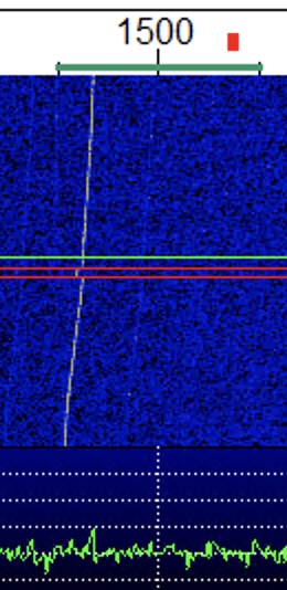
I’ve had the injection board for some time, but just never had the desire to open the 9700 until it was really necessary. I have to say that the idea of opening a radio with the price tag the 9700 has to fix an issue does seem somewhat bizzare, but equally I’m glad that leo bodnar solution requires no soldering but stil requires a good amount of care and attention.
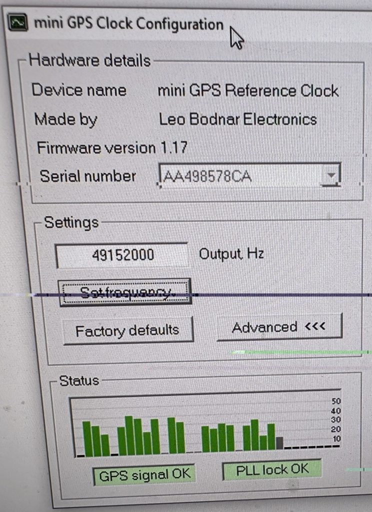
I ordered the mini GPS clock and was pleased to see that it included a GPS Antenna and USB cable, its worth noting that you will need a SMA Cable for going between the GPS clock and the radio itself, thankfully I had several good length ones here in the shack thanks to my work on the chipwhispherer capture board.
My reference video, which is also linked from the Leo Bodnar site, is the ‘gps lock you icom ic-9700’, I watched this several times before even opening the radio.
Having watched the video one last time, I set about opening the 9700.
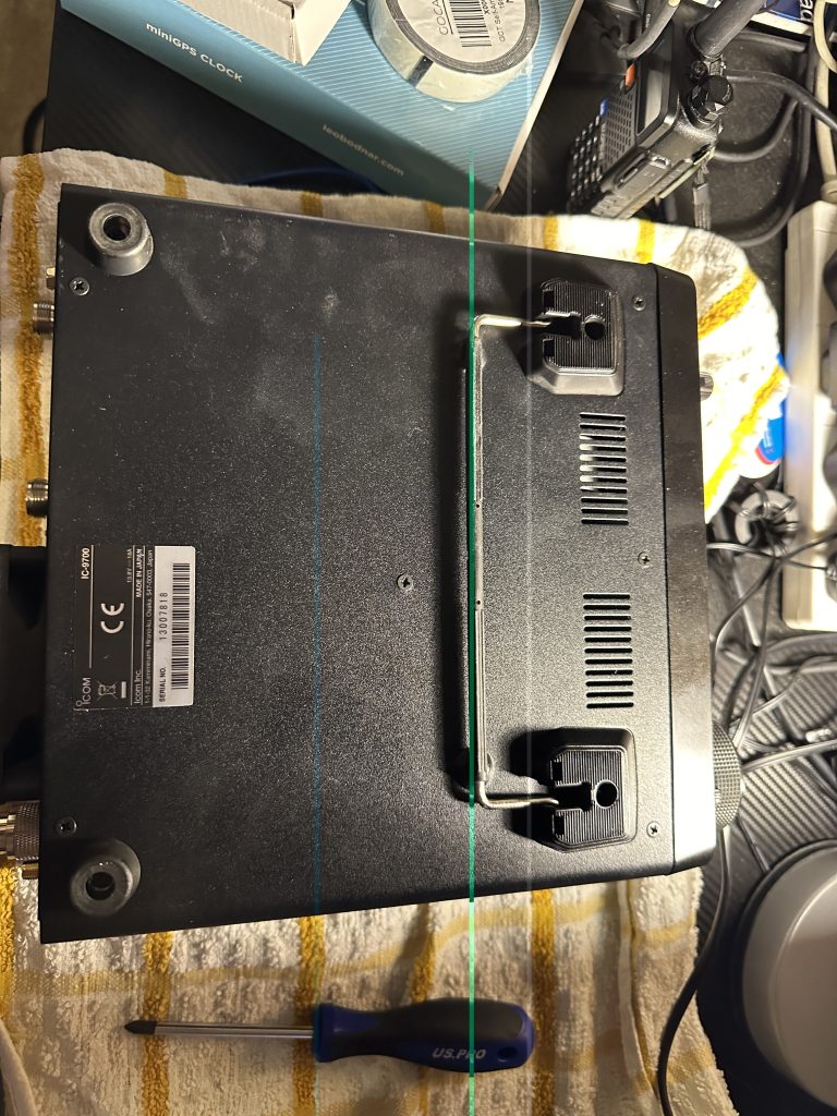
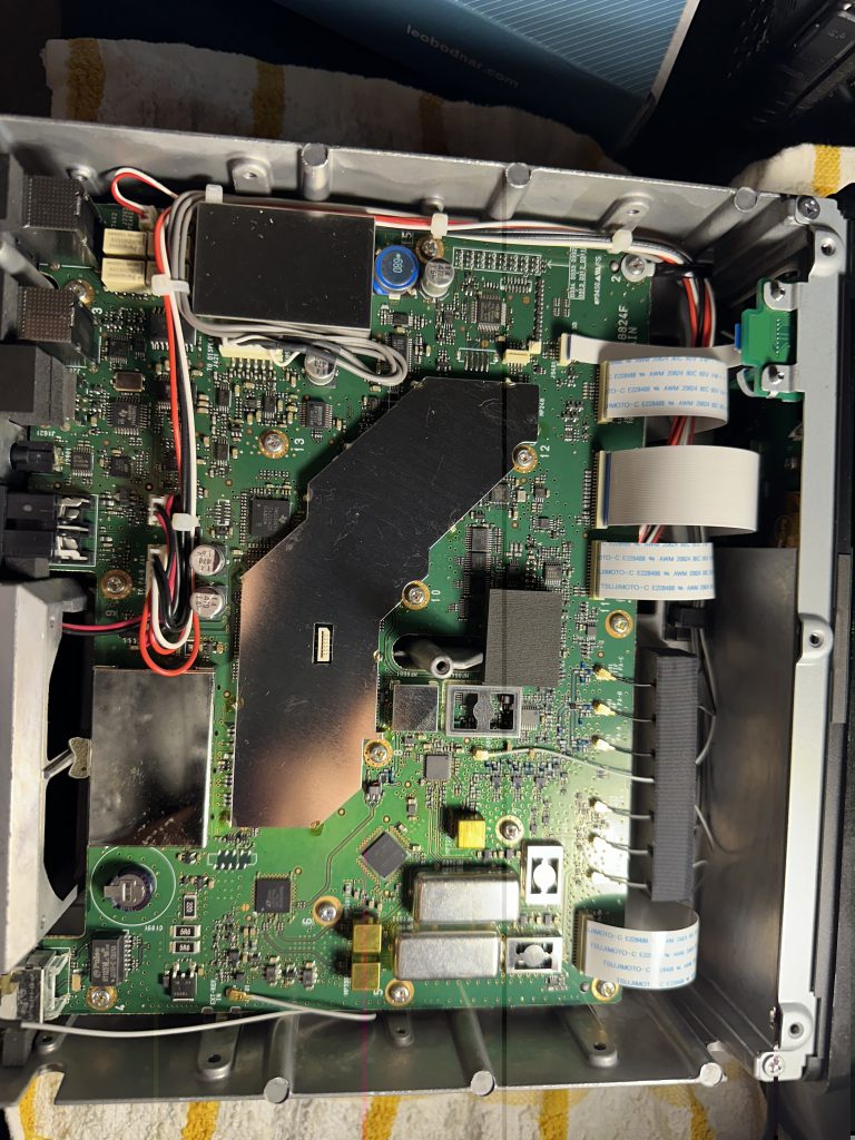
I waited an extra day before opening the radio as I dont have any JIS screwdrivers and didnt want to wreck the screws on the 9700. I found a nice set for £12 on Amazon that done the job nicely, tho some screws may of been ‘locked’ in, a good strong ‘tap’ of the screwdriver ensured the screws came out easily.

Having got the case open, i then set about removing the thermal protector and existing wire. I was trepidatious about removing the connector, its very small with alot of components around it, with a little ‘wiggle’ it was removed. I used a bike-kit socket set to remove the connector from the chassis and stored in the board box.
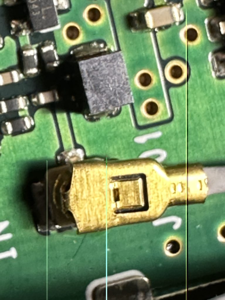
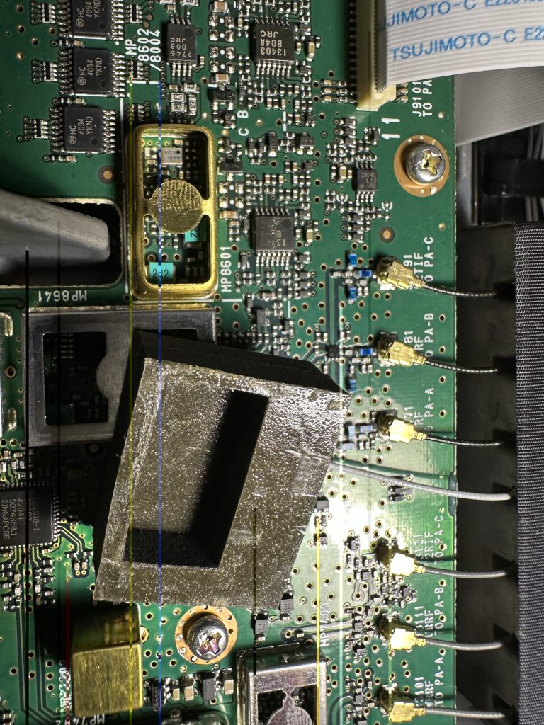
I then went about fitting the board, i first sized up exactly where it would go and what screws to use, there are two pairs in the box, I went with the longers set which done the job well of holding the injection board to existing screw holes. I made a visual inspection with my phone to make sure the board was fitted correctly and should work correctly.
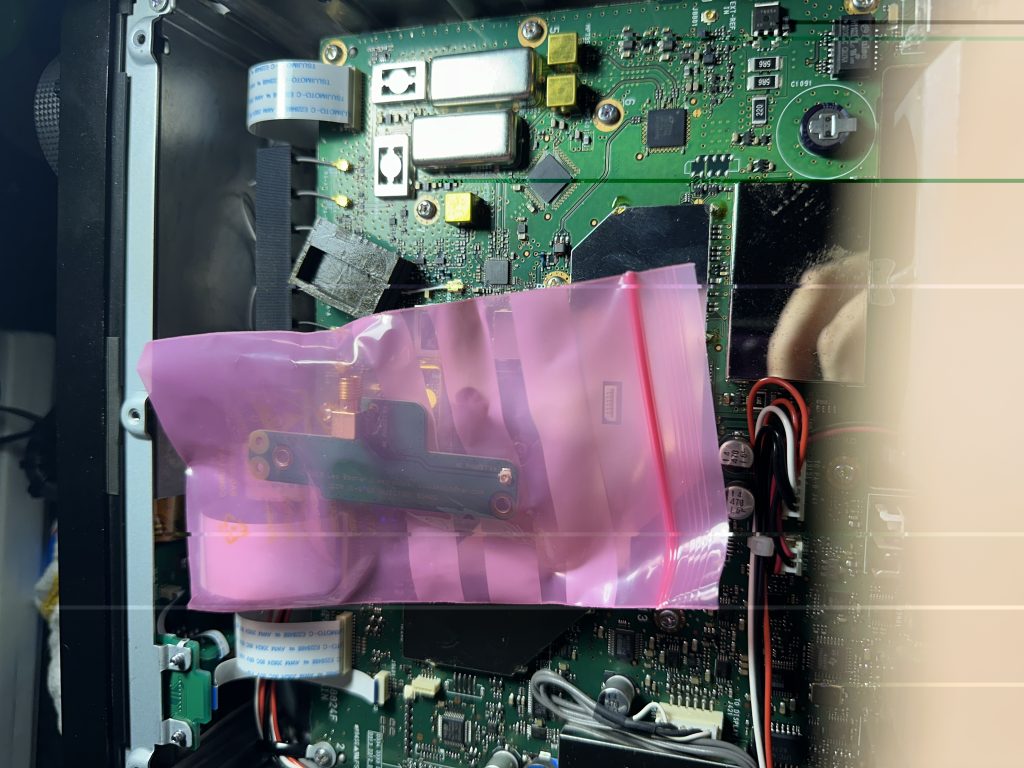
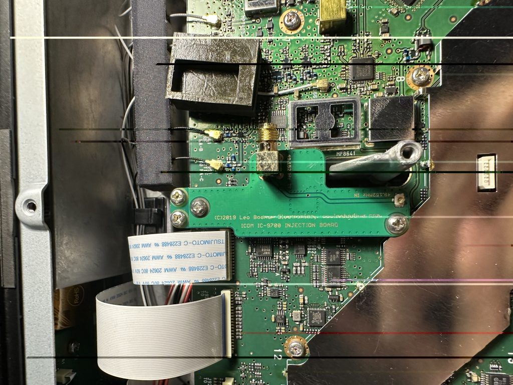
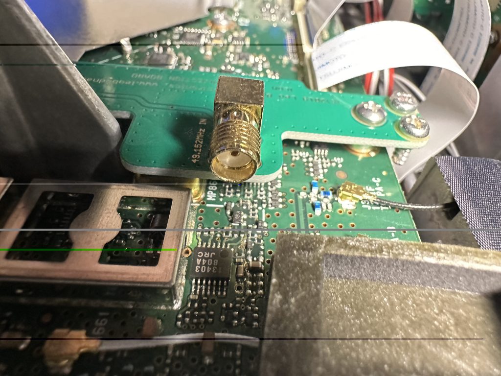
Once I had fitted the board, I put the power back and turned on just to ensure nothing had shorted/issues, then put the bottom case back on. I found getting the power connector on and off the 9700 really fiddly ! hopefully I wont have to remove it again ! 🙂
I then installed the software on the computer I use for the ic9700 that has PCSAT32 and HRD installed on it. I didnt see any Linux software for doing this, so was at advantage running Windows in this instance. I liked the GPS Clock had a blinking LED on it as well. I hooked up the external antenna and was soon picking up the GPS signal without issue.
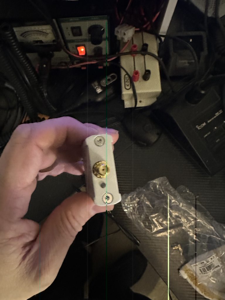
For signal generation I setup my IC-705 with a 2m/70cm whip antenna, and set the power output to 0, i was able to use the morse mode to generate a repeated CQ TEST 2E0FWE as my frequency marker, I could then use this to ensure the injection board was working correctly.
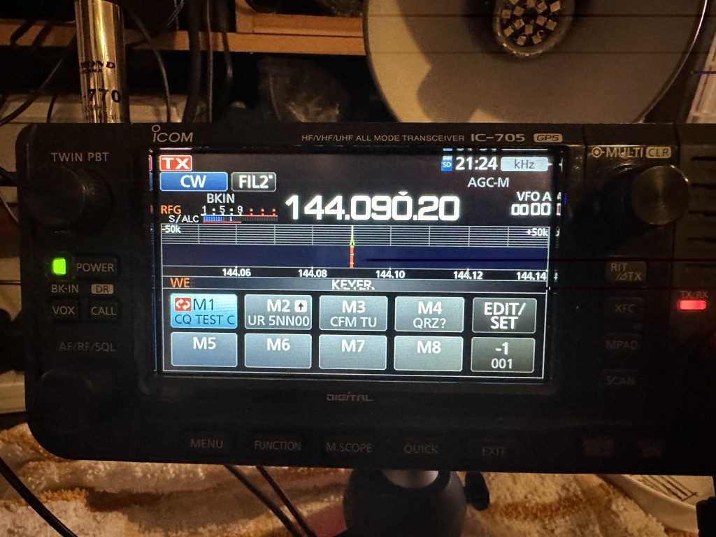
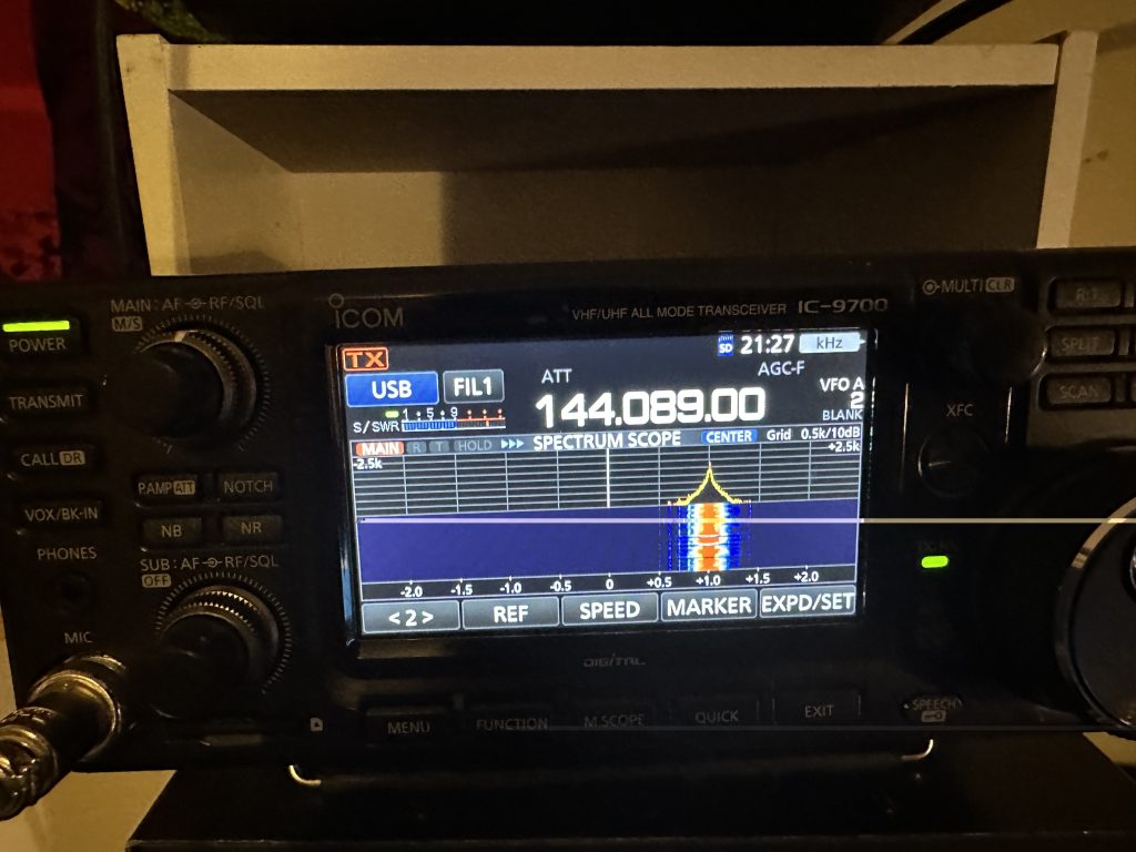
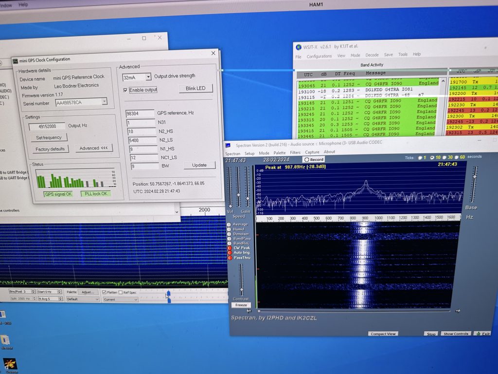
I was really impressed of how well the frequency locked and the stability of it. It only took me a couple of hours tops to watch the videos and fit everything to have a radio which will work well on digital modes.
Hopefully you will see more videos of me using the digital modes on the ‘birds’ soon, but am glad the radio is up and running !
When I’m working during the day, I’m using WSPR to test the antenna and even tho its an eggbeater its doing great with WSPR.

73 2E0FWE
