So having got the bhi DIL DSP Receiver, the amount of QRM I was still getting wasn’t good. Although I was slightly tired, i really wanted to solve this issue.
I followed the DX Commanders Youtube posting on QRM here
https://www.youtube.com/watch?v=xF2wFJBpu_I
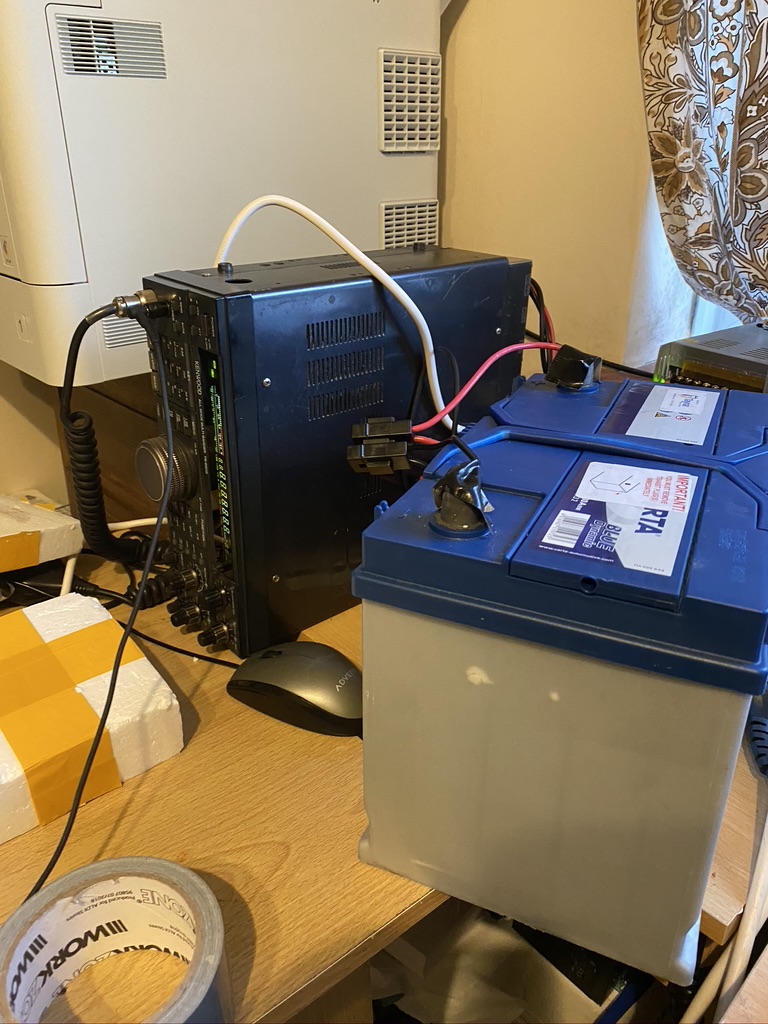
So i then set about unplugging things around the house, the first thing I found was an electric blanket ! That put out a huge buzz, but there was still plenty of ‘noise’ amongst the signal. I turned everything off in my ‘lab’ and used a car battery to test –
Car battery, less buzzing…
So off a car battery there was a big reduction in noise, so it was something in the powersupply or surrouding room
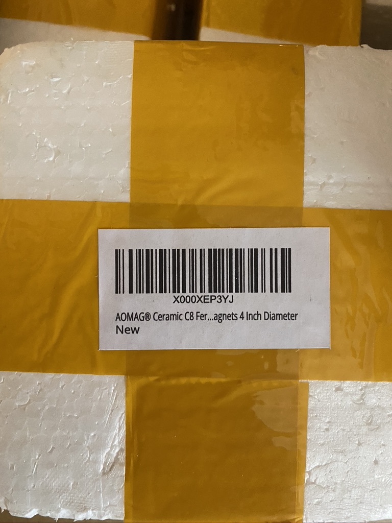
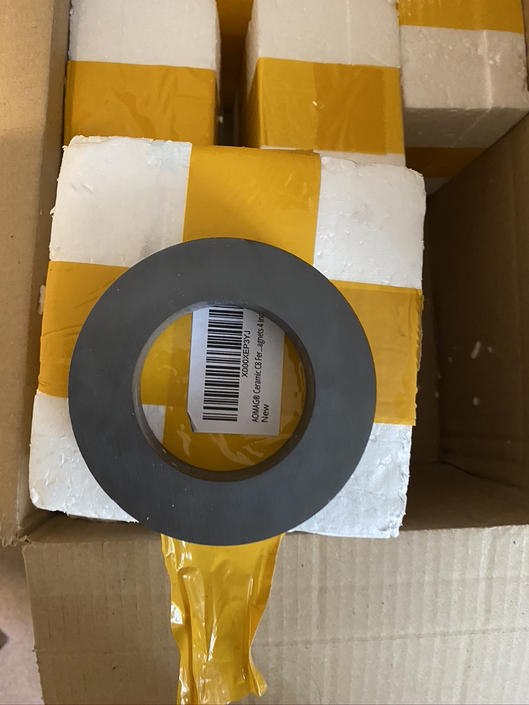
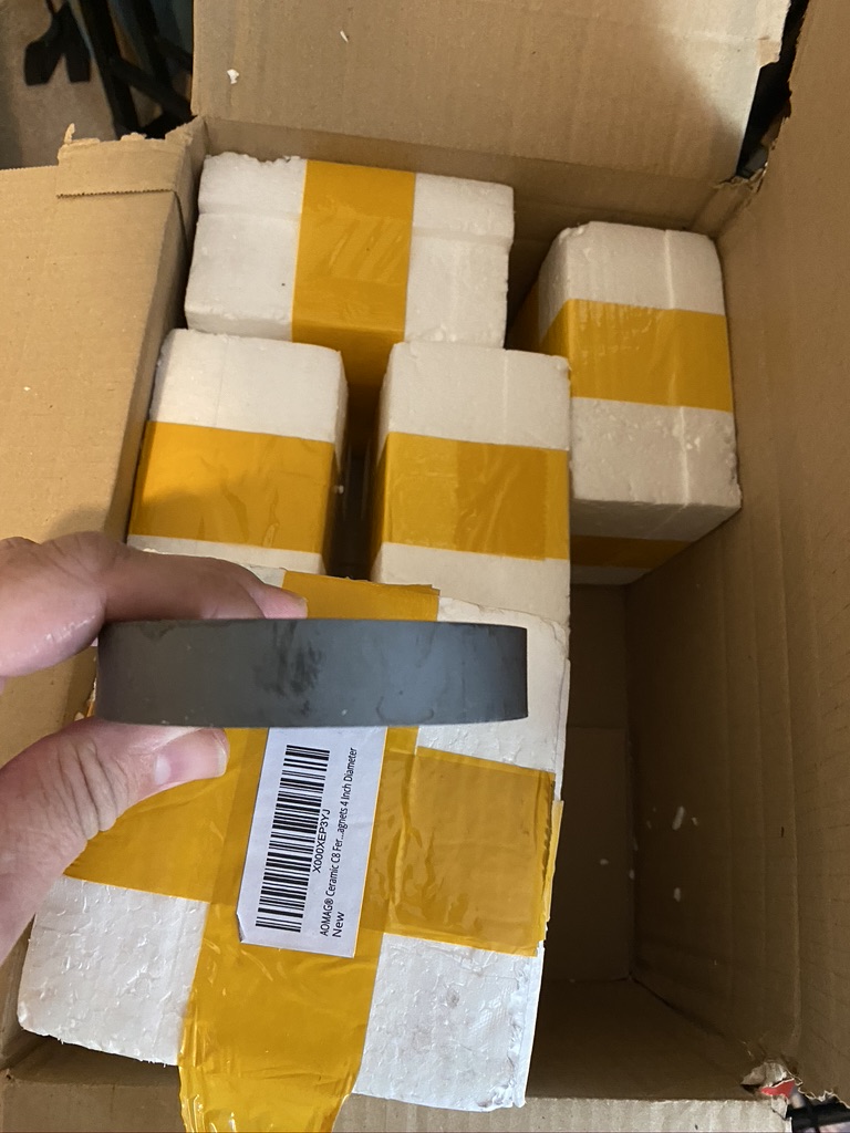
At this point I used several of these magents and put on the power line in, HF and transformer
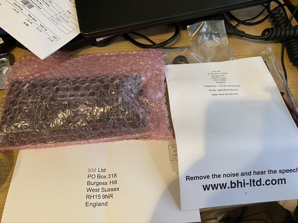
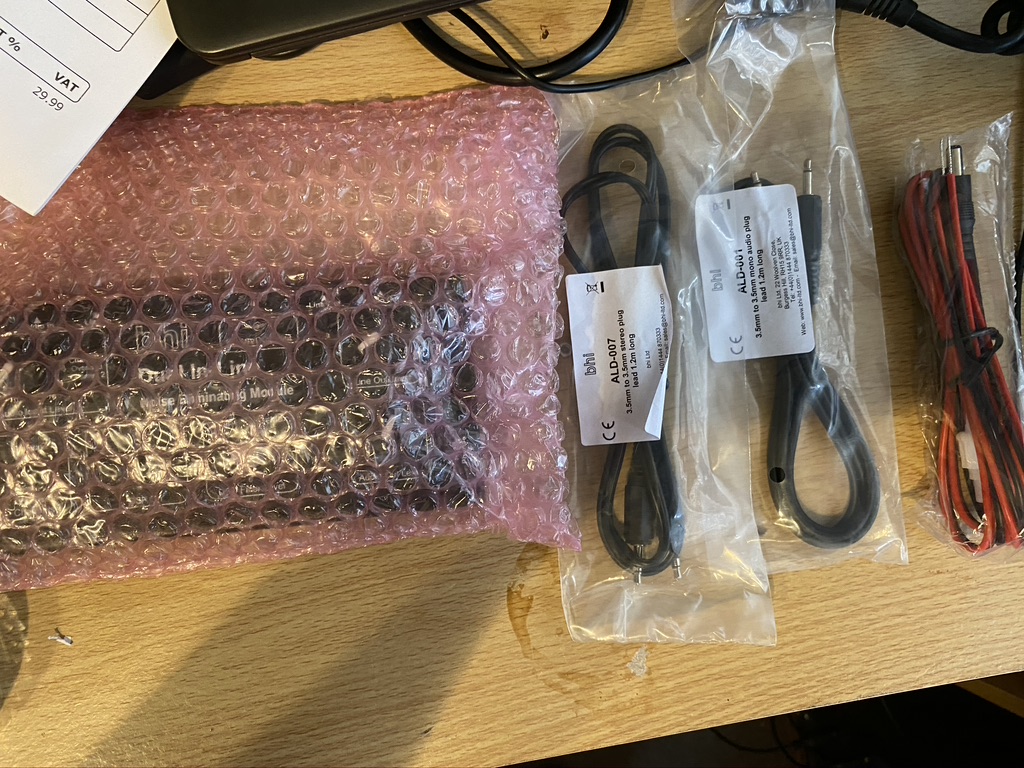
very well packaged
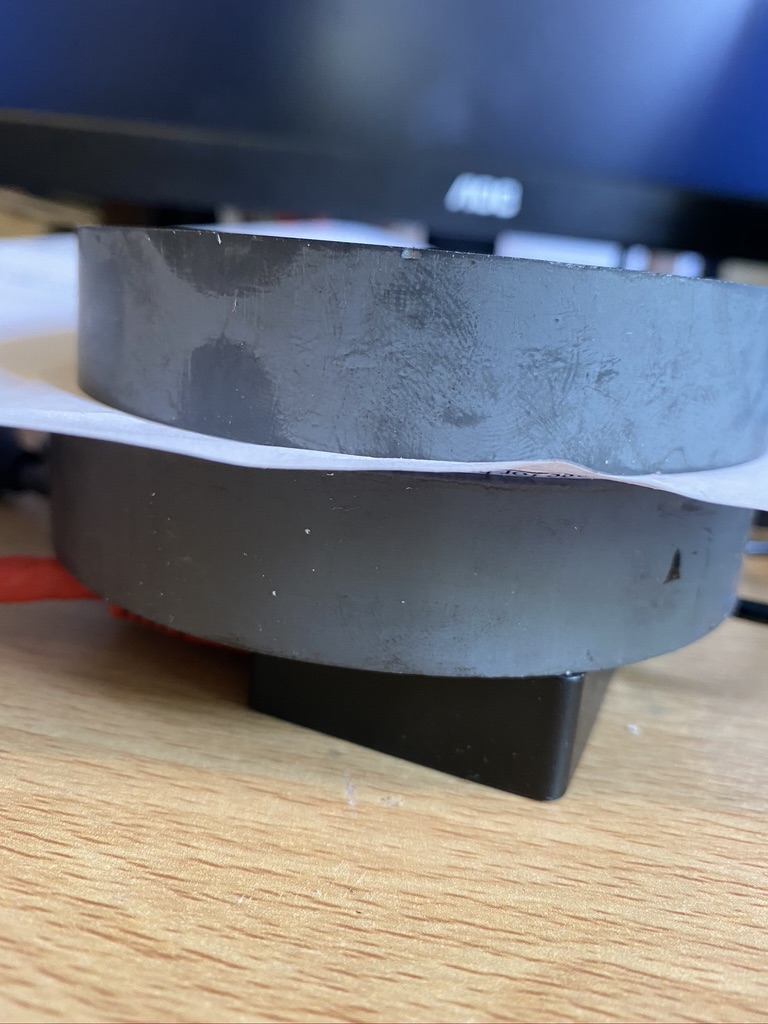
big ring
the thickness
lets see what happens when you put two togehter
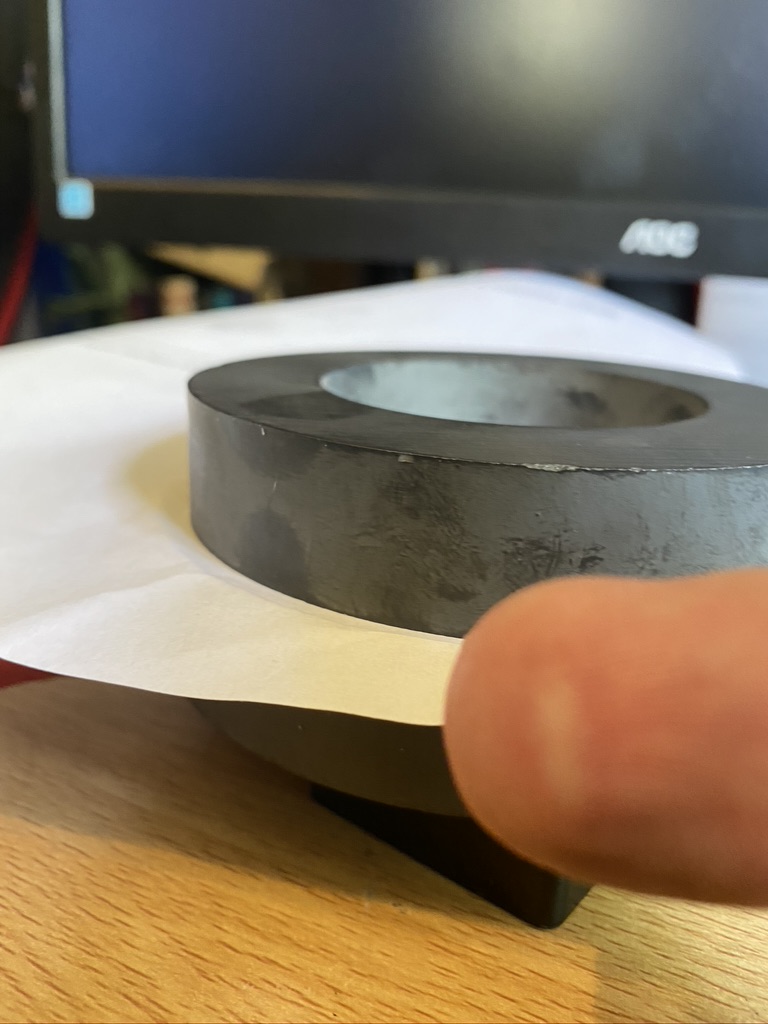
thankfully this is just my finger…
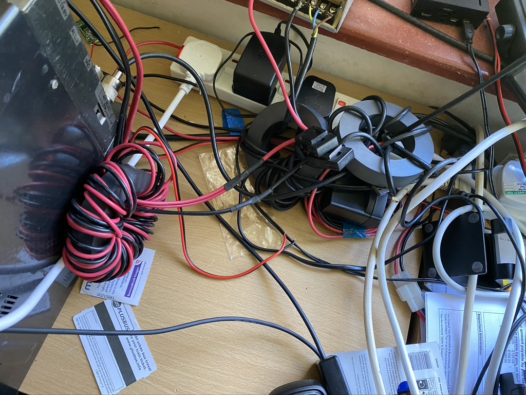
I set about winding, but still noise 🙁
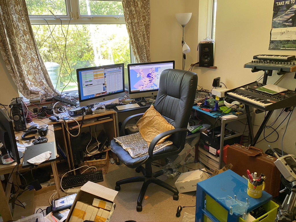
what a messy lab
i’m working in this mess 🙁
winding and messy
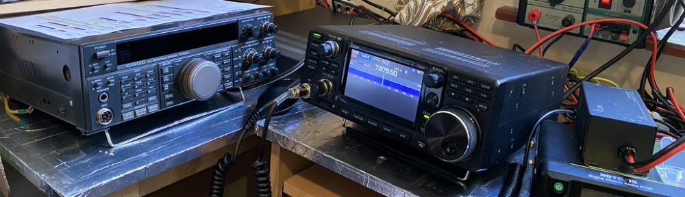
By this time, i was still getting less, but still a big interference. I unplugged *eveything* from the transceiver and it stopped ! So it was something being plugged in.. I went thru each device, lo and behold the xggcomms CAT port was the main offender ! By this time it was getting late, and some much needed family time with a few brews and a good film was required to consider the next steps.
After the film and a nice walk of the dog at 11PM (to avoid other dogs/runners/etc) I cam in and started searching for ferrite cores, sure enough amazon had a huge variety, and on PRIME next day, so I ordered think, great i can get these Monday and get going ! Amazingly, even tho i ordered these at 11PM+, they was here the next day ! I was going to tidy the lab up, but set about attaching all the chokes I could to the cables between the mac and transceiver. The difference was amazing…
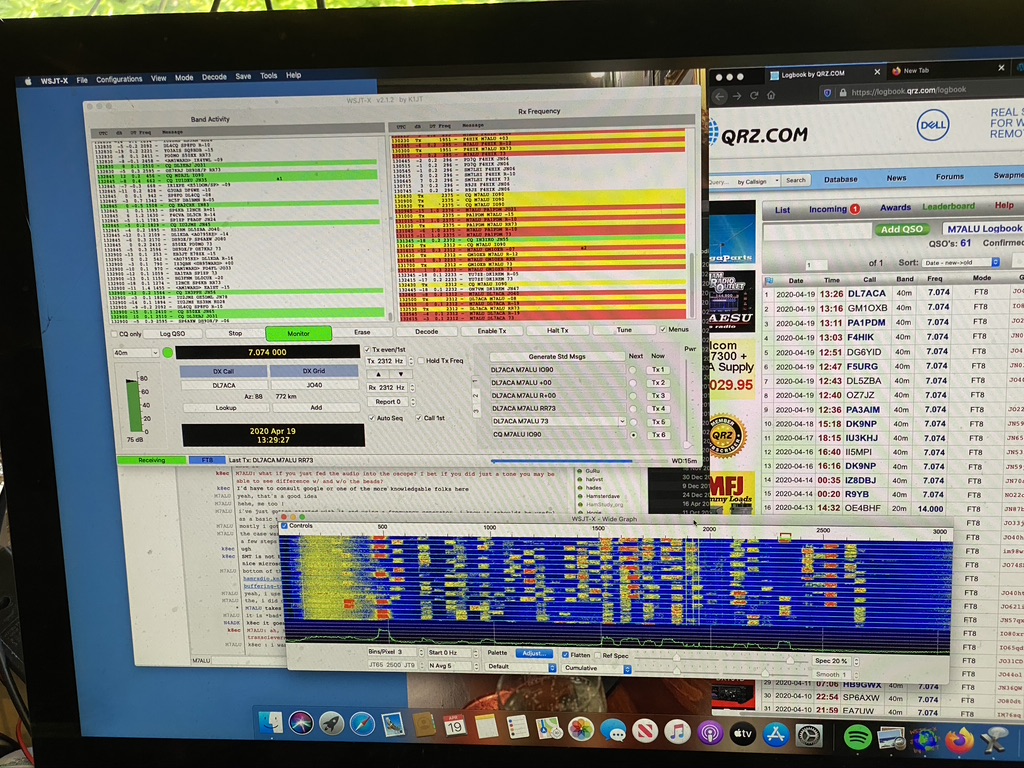
FT8 came alive very rapidly !
Within a course of an hour, i had made 9 QSO’s on FT8 on 40m, with 3 already confirmed on QRZ ! I was so happy that everything was working really well !
I think I am going to upgrade my chinese power supply which is meant to drive power-strip lighting, which is fine for VHF/UHF (A recommendation from FRED IN THE SHED on 27Mhz) but for HF I will get a decent 30~40 Amp campable linear PSU for the Kenwood to further reduce the QRM.
Now to stop playing on WSJT-X and tidy this place up !
This is where I miss being a amateur radio club, asking advice of seasoned operators. Thankfully I have my long-time IRC and expat friend PA2TG to call on assistance. I asked about eliminating QRM on HF as I was looking at the many different options available, and varying costs.
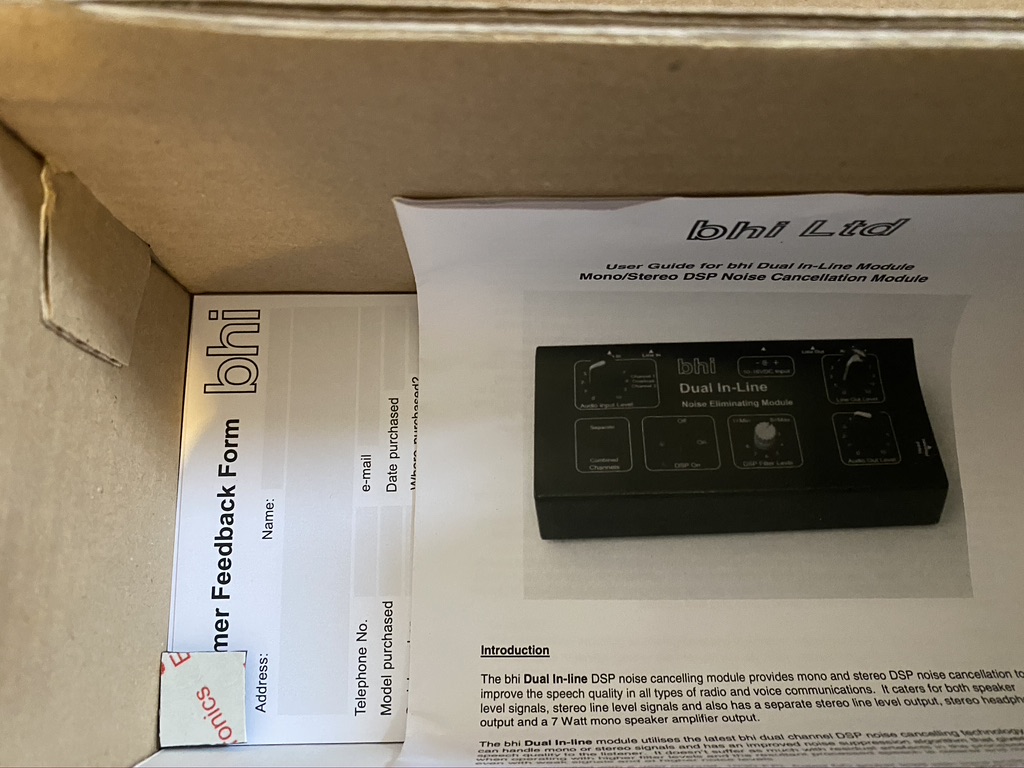
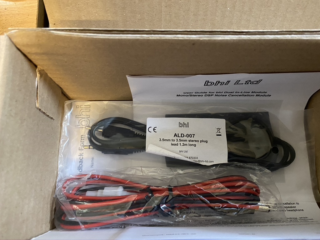
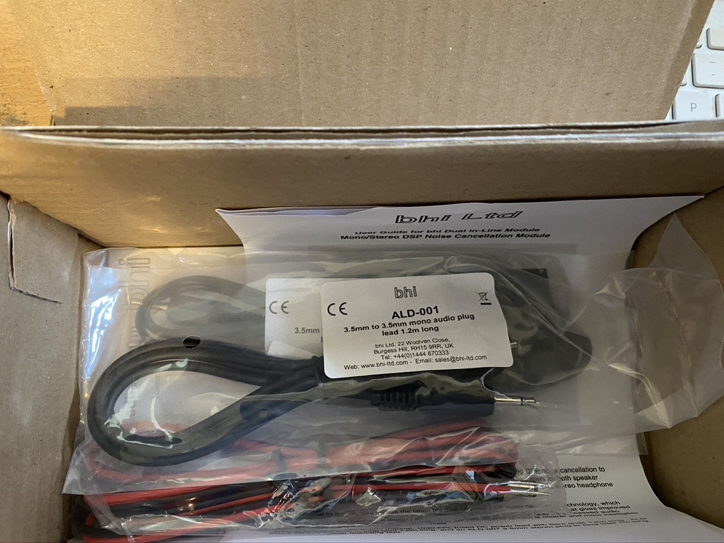
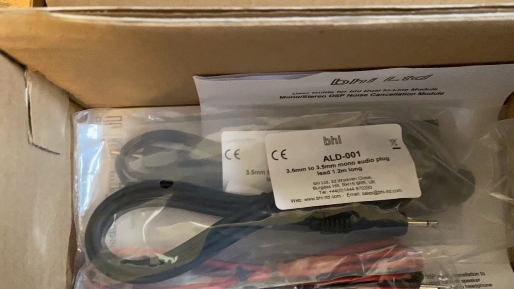
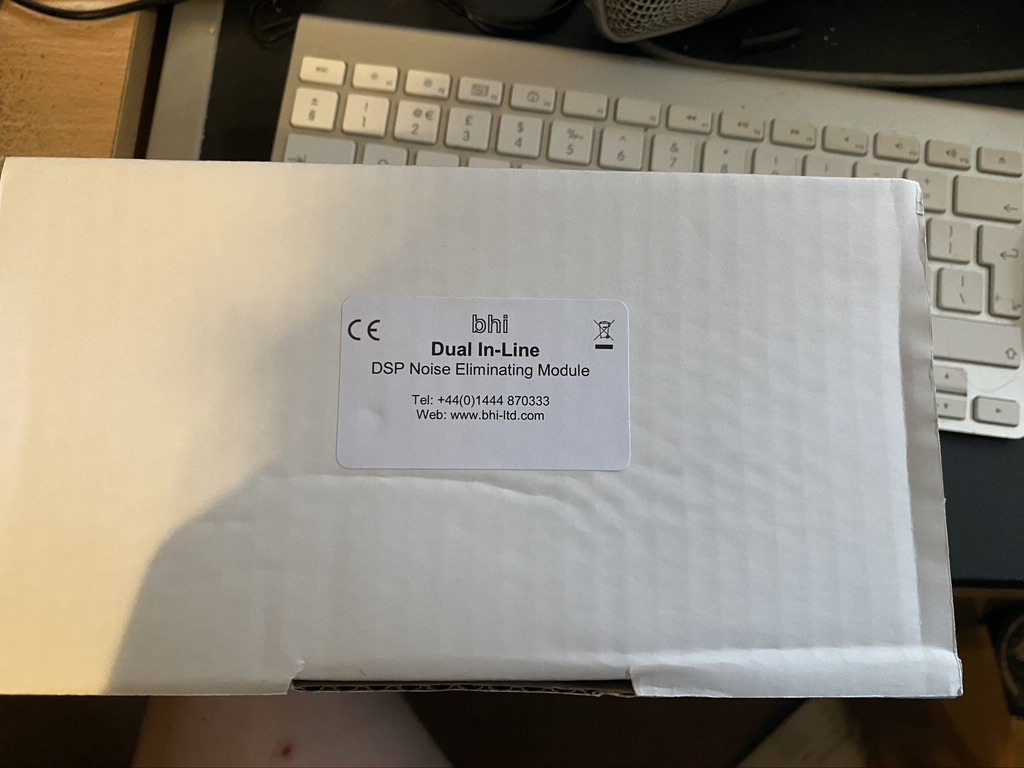
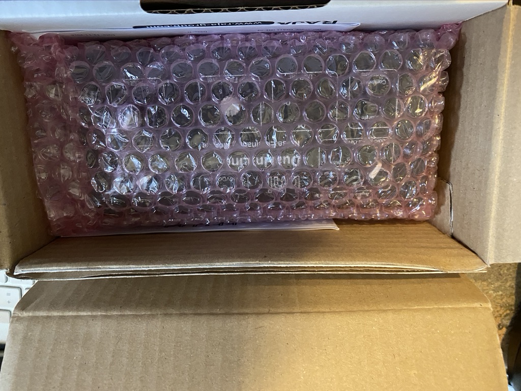
After reading my email, PA2TG suggested the BHI Dual-In-Line unit for me, which I ordered from RadioWorld who were incredbly prompt with next day delivery! Whilst I wont do a full review yet, here is the unboxing of what looks to be a very worthy addition to the shack !
BHI Dual In Line Unboxing
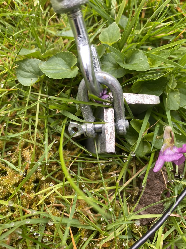
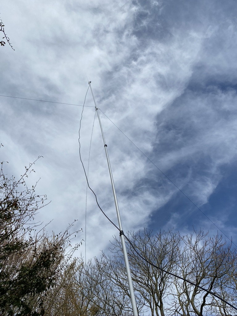
I also take my responsiblity of being a Amateur Radio Operator seriously, as much as its a ‘hobby’ it is very well taught module of ‘Saftey’ in even the Foundation. Some may laugh at ‘wiring a plug’, whilst I found the difference in fuses and grid types very interesting ! One thing I do take seriously, and check my antennas every single day. One ‘benefit’ of the lock down is that my antennas are staying up longer, and the guying/mounts are amazing, but today I found that one had completely come off ! Under observation I quickly repaired the guy rope and restored the tension to the mast.
Saftey inspection found the pin had completely come out the ground stake, quickly fixed and tension/support restored.
I have been doing other things in the shack, but will right a summary rather than lots of little postings.
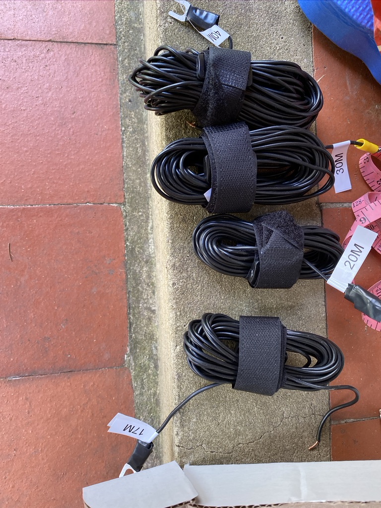
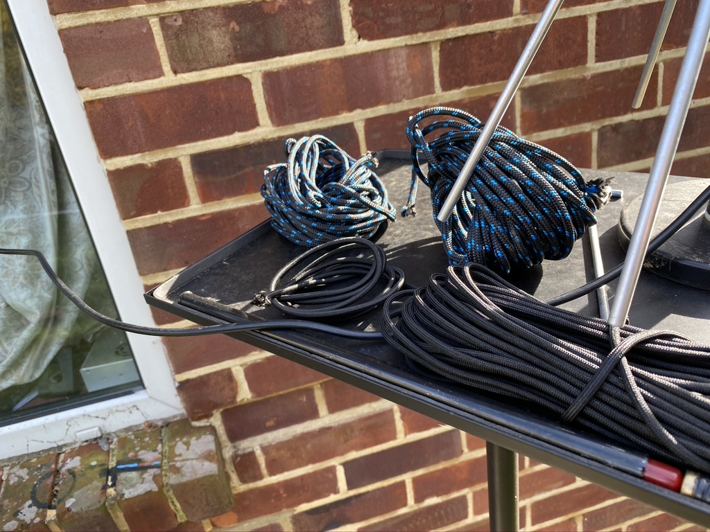
So after having so much fun on 40m, I wanted to get the rest of the wires up
So far I have 40 and 30m up (the longest wires), with 40M getting the most use on FT8 (Plenty of contacts logged, and several confirmed via QRZ!)
I had two remaining shorter cables to mount, the 20 and 17. 20 was of particular interest as it has so much going on and seems busy day or night !
Before adjusting the antenna i done a quick test on 20m, and the S.W.R was way off the meter on the radio, so was very much needed if I was going to get out.
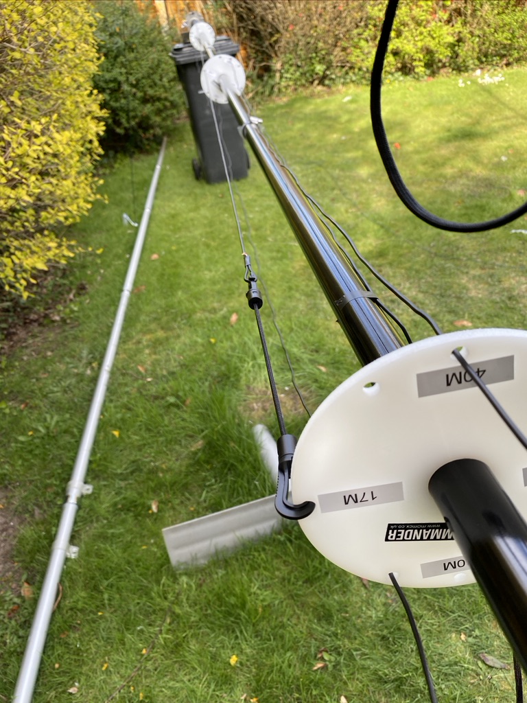
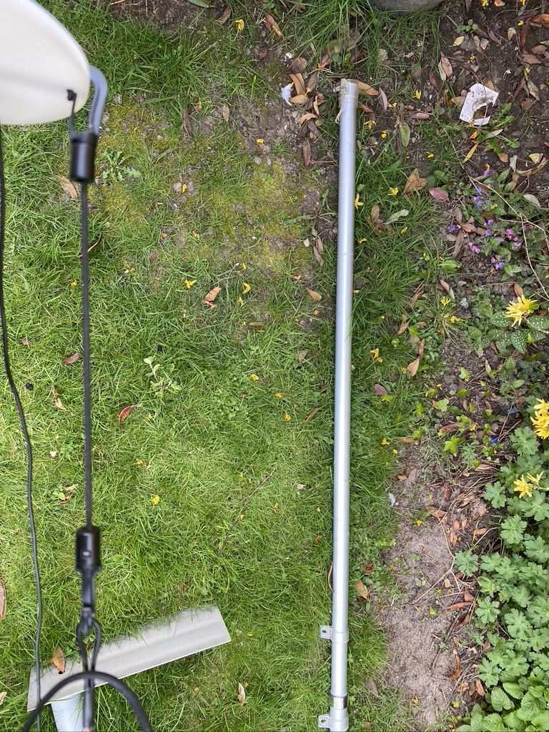
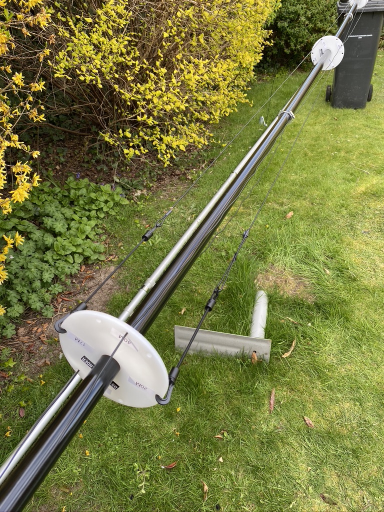
I set about re-measuing the wire and 20m required no correction thankfully and 17 only need 6cm adding, which I set about doing. I brought the mast down and rewired.
I started the transceiver and put wsjtx onto 20m. Sure enough within a few minutes, i had made contact in Poland on 20m with a very good db result.
I’ve not tested 17 yet but I’m equally confident that I will be able to get out.
As per previous exercise, here are the S.W.R. measurements with 4 elements up
Amateur Radio Frequency Measurements
Meters
Mid Frequency (Mhz)
S.W.R.
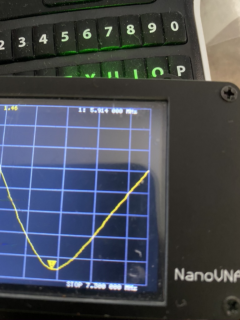
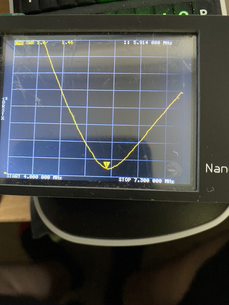
40m
7.1
1.52
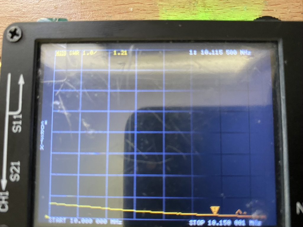
30m
10.115
1.21
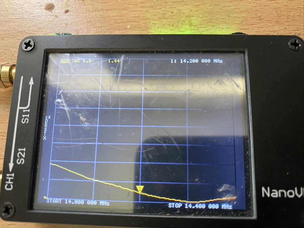
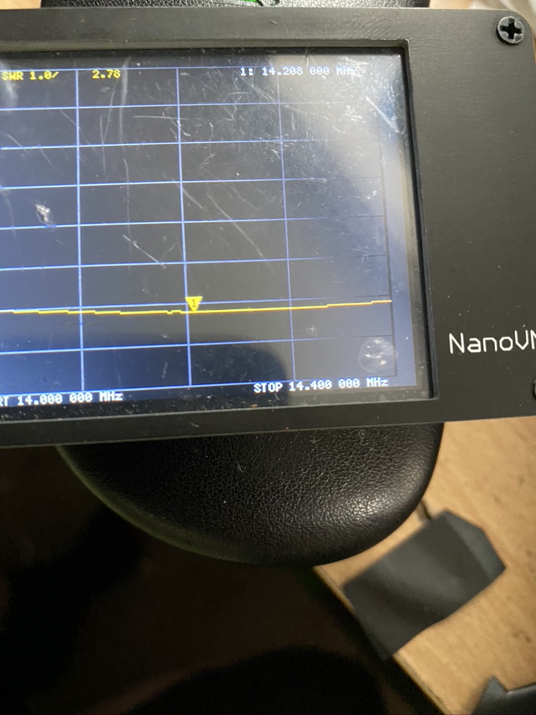
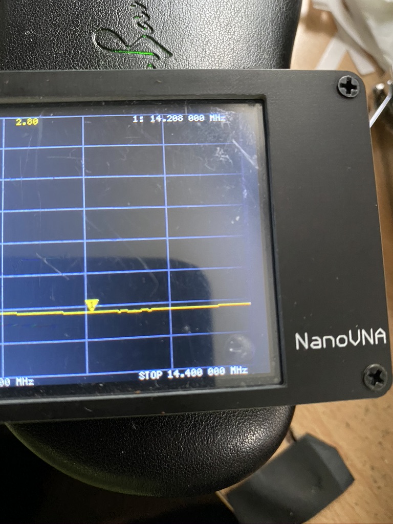
20m
14.2
1.53
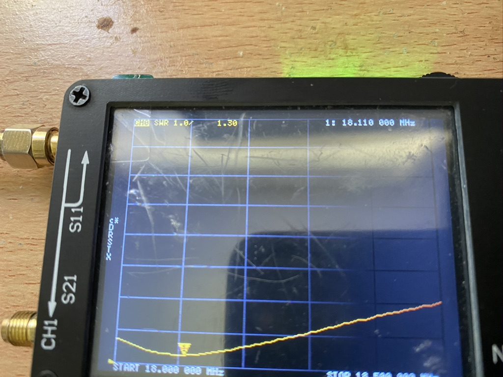
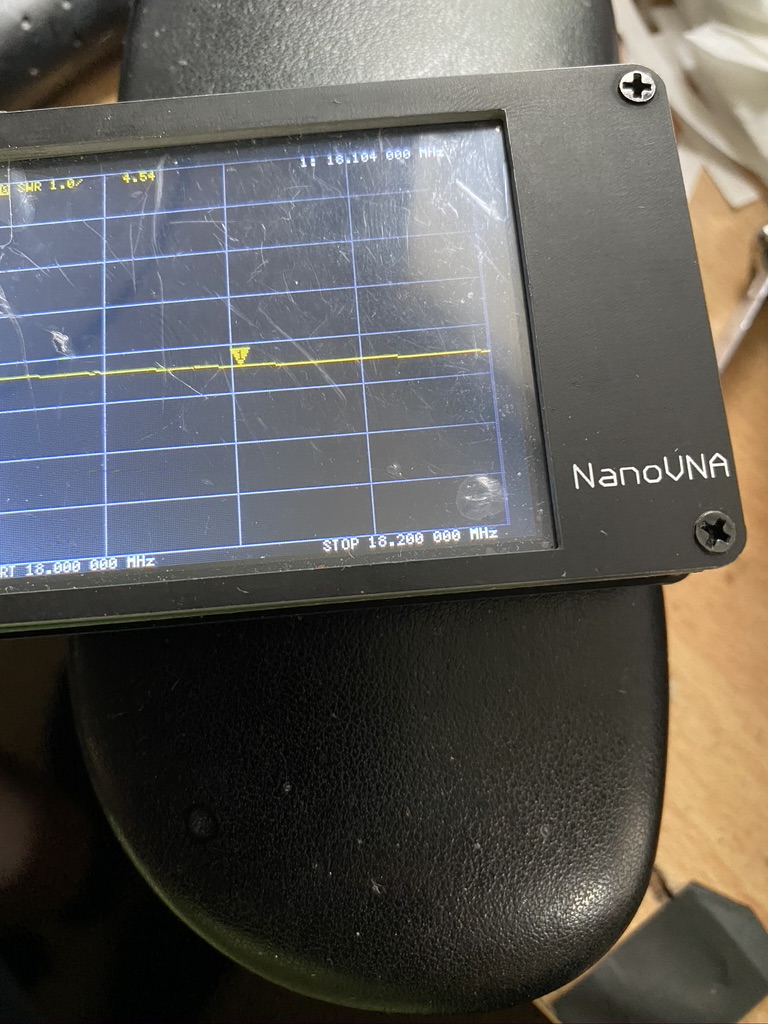
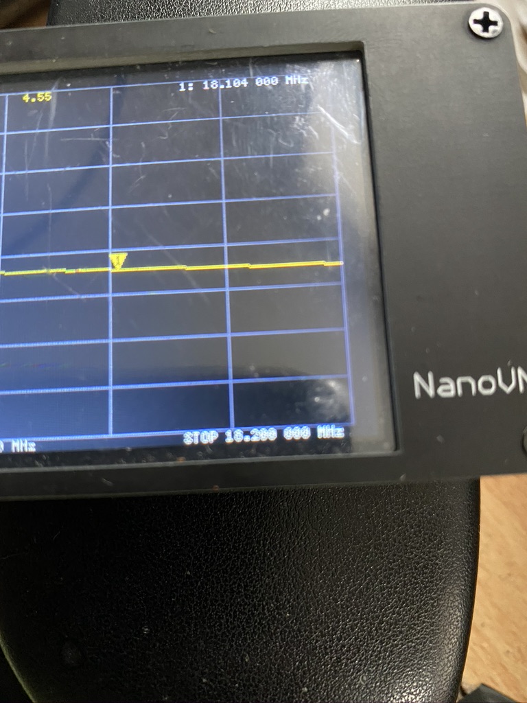
17m
18.11
1.34
Amateur frequency readings after adjustments
So I am very satisified with my DX Commander – I may replace 30m with 80m, but at the moment I have plenty of frequencys and modes to work, even with 10W of power. Thank you Calum the DX Commander for this amazing antenna system !
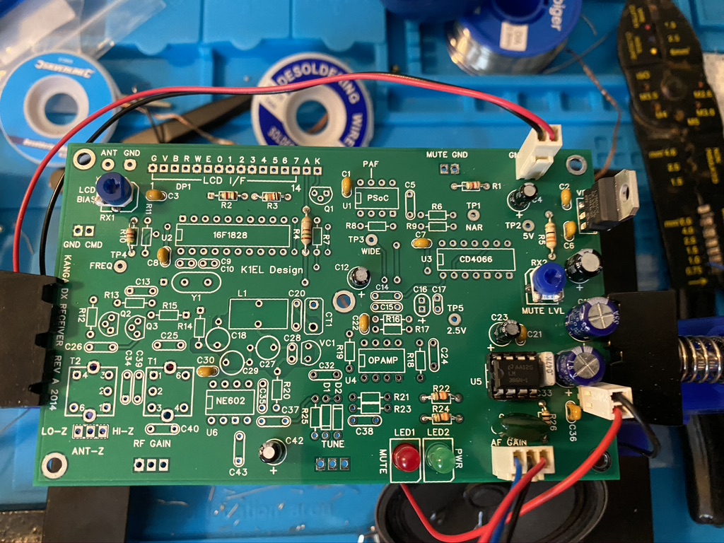
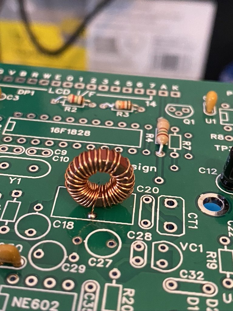
The next stage in the kit was to complte the Variable-frequency oscillator (VFO) & VFO Buffering. The first part of this is quiet detailed and delicate, and wanted to do it seperate from the regular resistor and capactiors stages. The instructions do say to add the Toroid towards the end of mounting but given its positon on the center of the board, it wont get in the way from what I can see.
Toroid poisition is L1
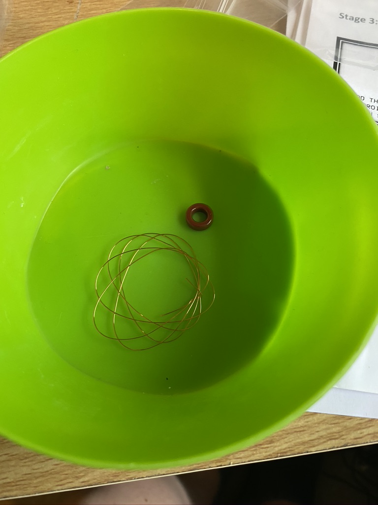
I done my usual task of seperateing the parts out in the small bowl I have, even tho there are only two parts at this stage, the magent and the 28SWG copper wire.
wire and magnet – how ti comes out the pack
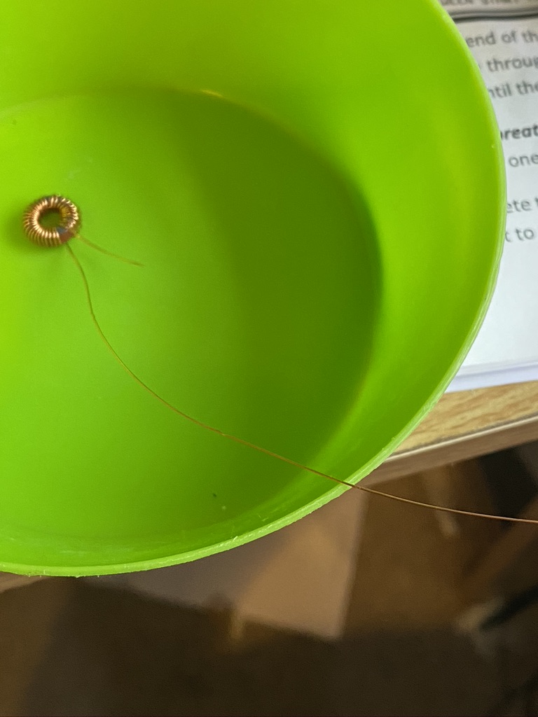
Firstly i straightend the wire out to remove any kinks, and using a combination of tweezers and my hand started to thread the wire thru. I kept 10mm (maybe +/- 2~3mm) as the winding start. After 10 winds, and still keeping a tight hold of the magnet and wire, not knowing how it would ‘behave’ i took a look at how it was ‘forming’ on the magnet. So far so good, so kept winding. I found that towards the end it was getting quiet tight, but not difficult, sliding the wire up and around the magnet gave me the space I needed.
the wound toroid
I felt having none done this before, it hadn’t turned out too bad, there was one little kink in the wire, but in 33 turns, thought that was an ok ratio for a newbie toroid winder like me !
I then set about how to mount the toroid on the PCB. I used a reference picture of how other people (or person) had mounted it. The next step was to cut then tin, so i trimmed the wire back to a length that would help with mounting ahead of tinning.
For tinning to work, i turned my soldering station upto its max power of 450c which created the desired ‘bead’ of solder and melted thru the coating on the wire, leaving a nicely tinned wire to solder to.
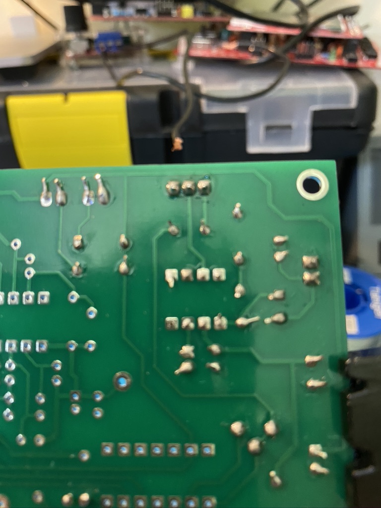
‘top side’ soldering
My soldering workstation is great in being able to ‘flip’ so i can easily solder components when pushed thru form the top. The Toroid presented a channege as there was no real way to exert any ‘force’ and flip the board over, nor did I really want to try the method of putting a small blob on one hole then to heat and push thru, as I thought the pressure would disfigure the winding. I’ve not used this ‘technique’ before, but I decided to use a ‘holding’ weld solder spot from the top on both sides. Indeed, rather than even move the board from the holder, I roated the entire board 360 so I could top-solder the other side in. From what I could see, this has worked very well with a secure toroid and good spaceing between the start and the finish.
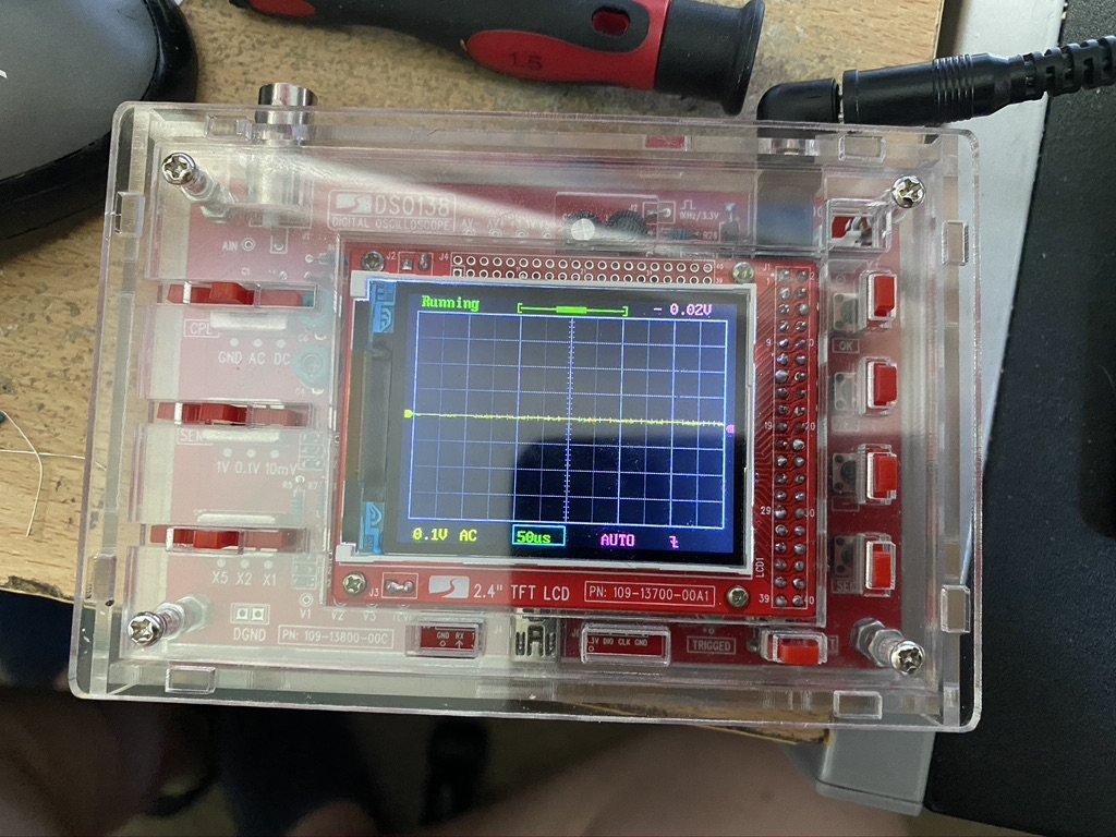
Oscilliscope – now in case.
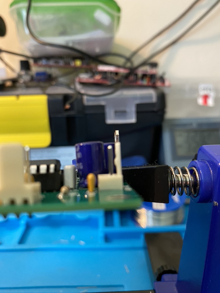
I also spent yesterday afternoon following this rather good tutorial on how to build the case for the DSO138 scope. Whilst I did face some challenges (one switch broke, which required a fair bit of rework to replace) It went really well and enjoyed using my frequency generator and following this good tutorial on how ot use it. This will be very useful when I need to test the VFO when the rest of the components are complete.
I set about the same method of splitting out the pre-packed components into a bowl making selection and testing easier. The instructions again are quiet clear, with good values of the resistors and capacitors.
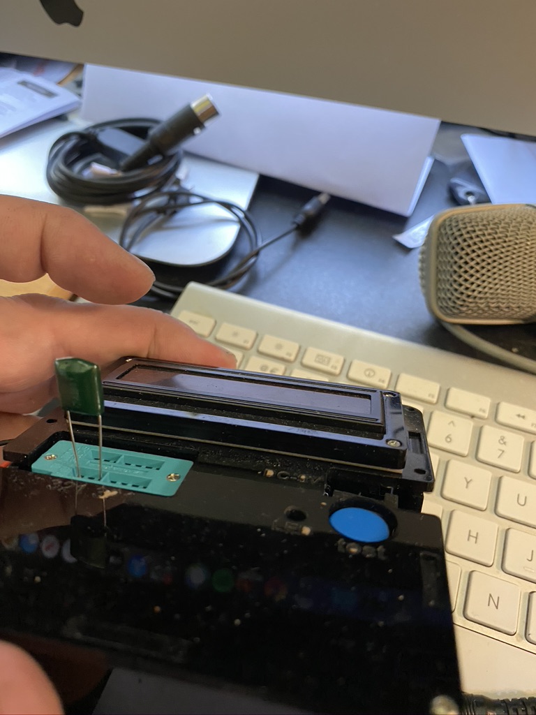
what is this thing ?
testing components for values
I did have to overcome a few mistakes, but whilst it was a ‘mistake’ for the board, its a good exercise for me in being able to correct issues, in this case the Mylar 100nF capacitor. The mistake I made was getting in confused with the smaller 104 labelled capacitors. I looked up a picture of a completed board, and can see that the ‘mylar’ (green) capicator was needed to be changed. Using some solder braid and solder sucker, I was able to cleanly correct the incorrect component.
Captain Pablo
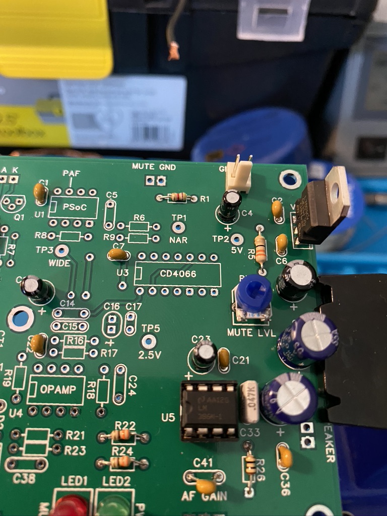
The LM380
Getting molex heads mounted
LM380 + Captain Pabo
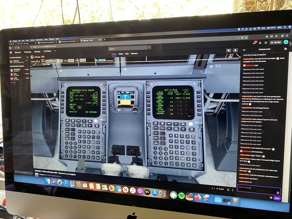
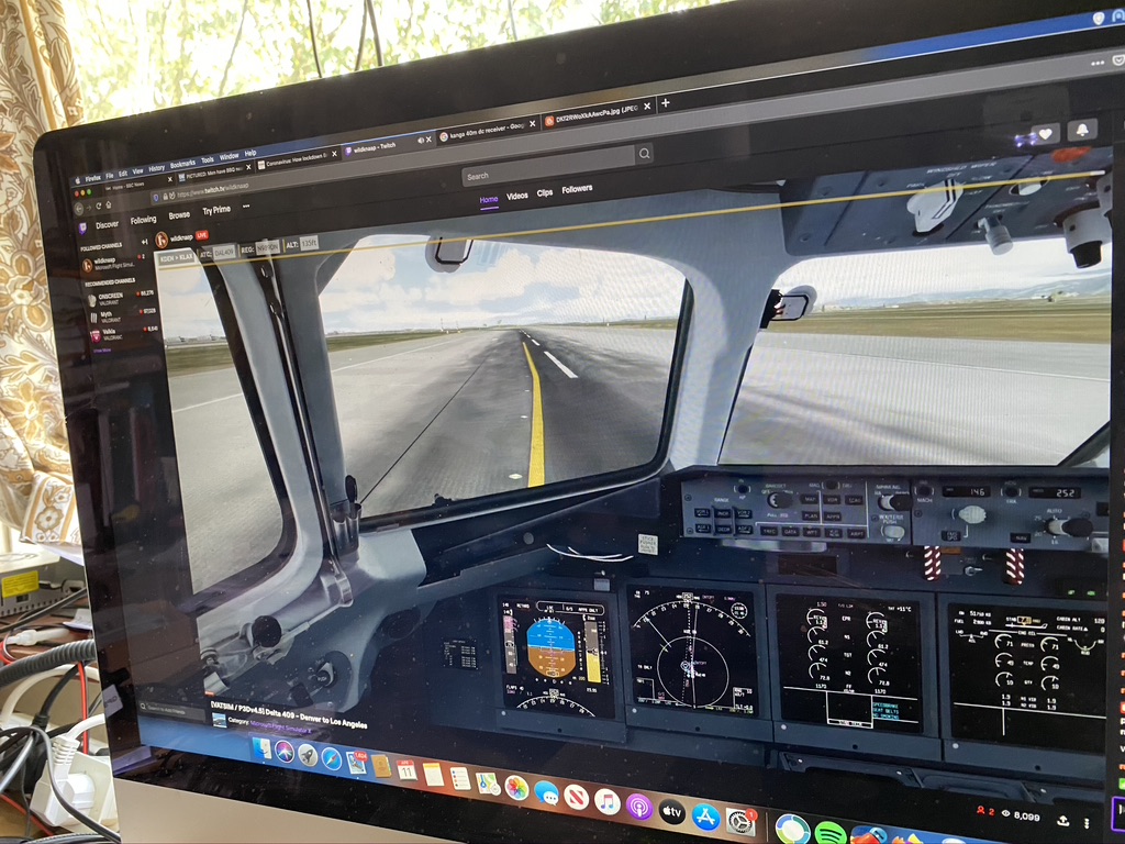
So I had an email ping me that my recently re-aquatined friend Pablo was flying (in real time), and was able to watch the video of his flight and the real-time radio transmissions. It was utterly amazing as people responded to the flight requests ! It was good having some ‘chat’ banter as well.
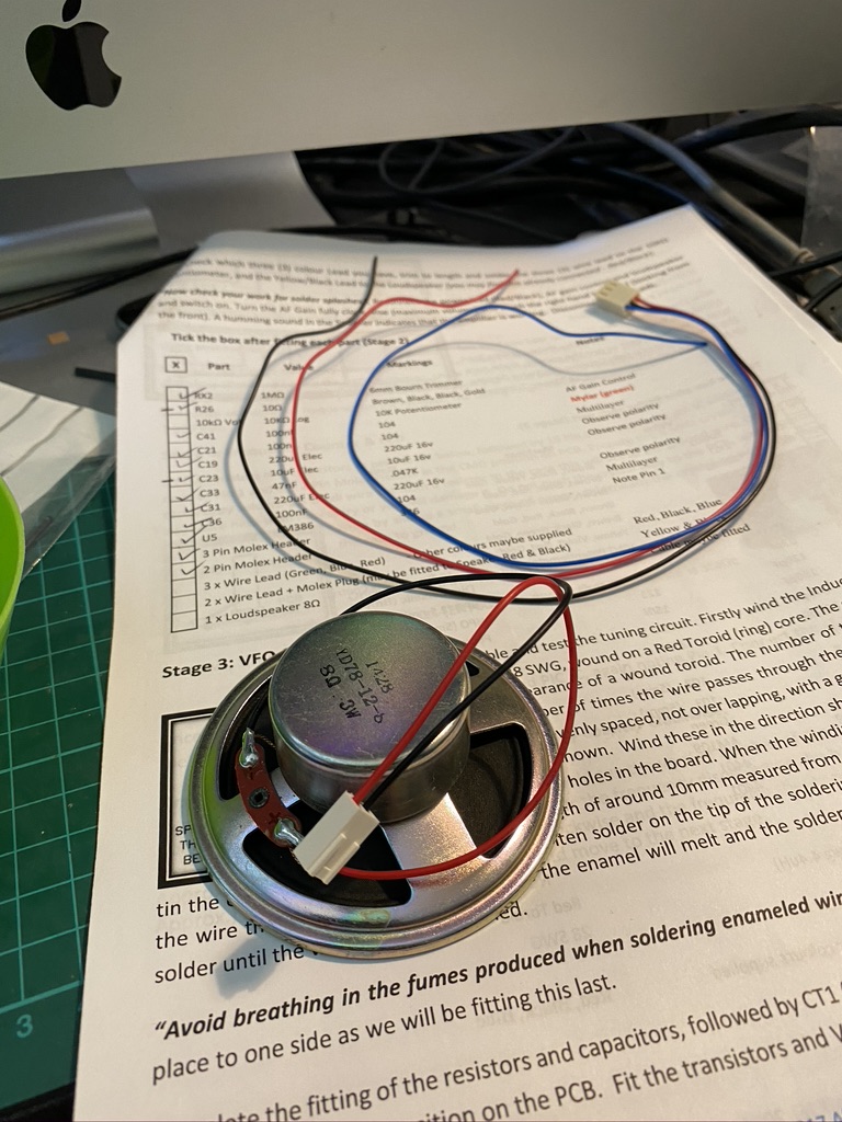
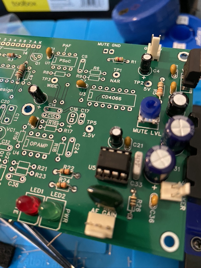
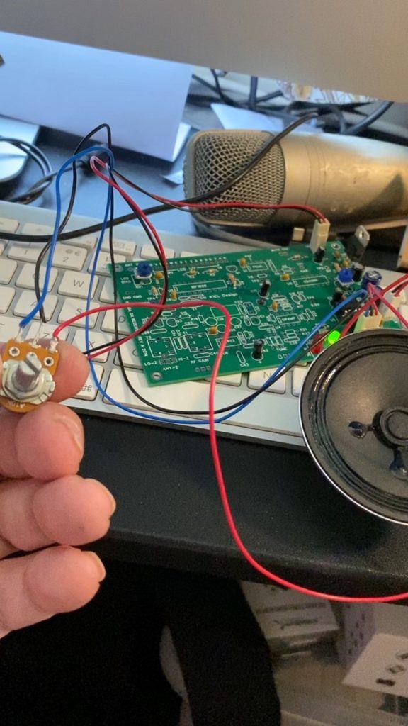
I set about fitting the one IC at this stage, the LM380, a simple audio amplifier and the required molex heads to connect the loudspeaker and variable resistor, all which went on well using the ‘solder a little’ then push thru method to get them nicely aligned and snug to the board.
rechecking IC holder
wire already installed on the speaker
Mylar cap replaced
And we have arrived !
Checking and Landing
So by now it was abou (I think) an hour into the build and i re-checked my work, having had an issue on an IC holder on the frequncy counter, didnt want to repeat the same issue. I found that i was a little light on the solder, so add a tap more just to make sure the pin would have good conductivity. Pablo had given us a great filght over the Rocky Mountains and had landed his jet via his controls, with an massive to taxi to the gate !
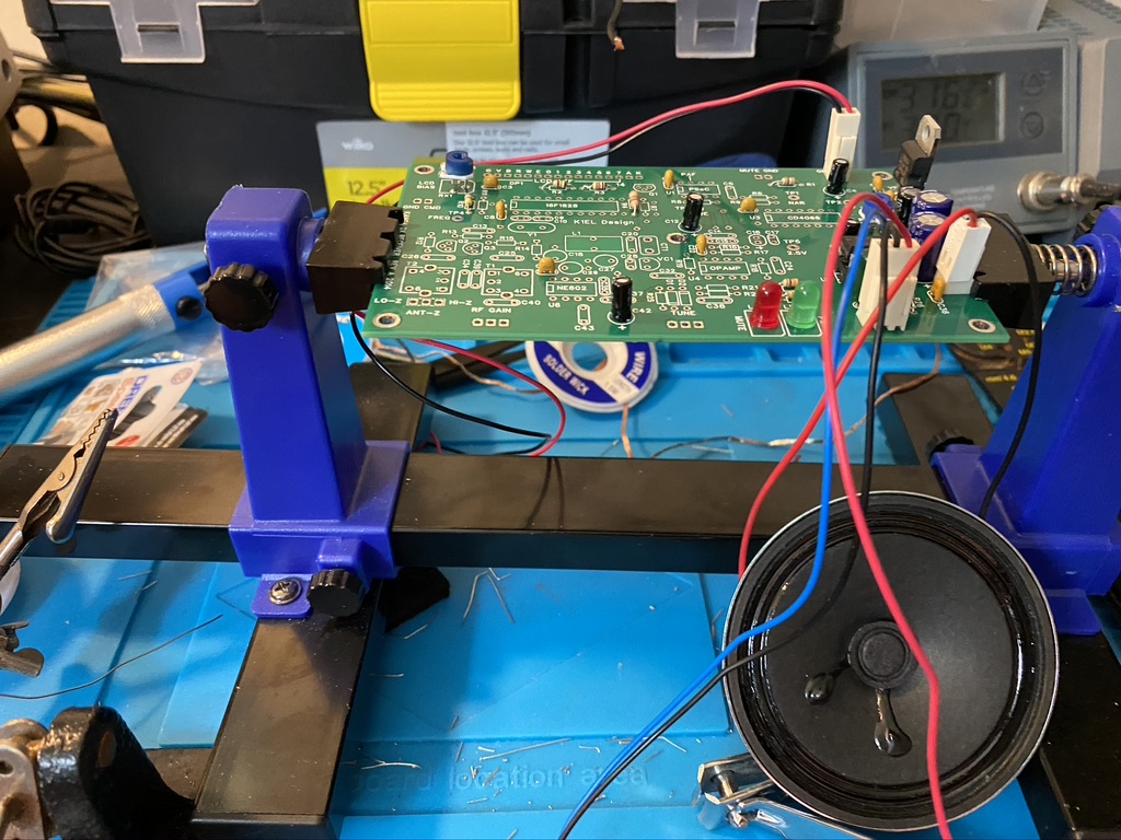
time to test the amp stage
and it works !
Testing !
So time had come to test, i hooked up the PCB to the mains adaptor on 12v and hey presto, a healtly static sound came out the speaker. I could use the variable resistor to control the volume, so everything was worknig perfectly !
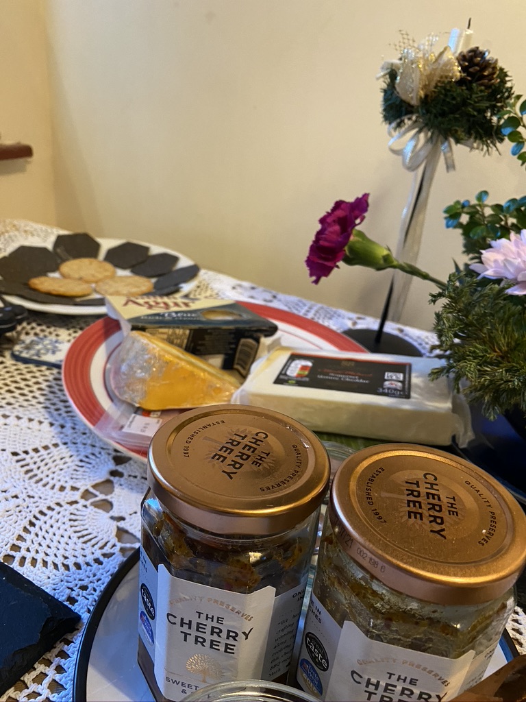
I had a great time building so far, more so thanks to the relaxing flight and chat with Pablo. I headed off to relax a little more with some wine and cheese myself 🙂
black crackers, some lovely cheese and chutney with a bottle of red
Very excited, having started a chat on RedditNet IRC Channel about my concerns of 10W usage on HF, plenty of people stepped in with ideas for me to try.
I then got some very nice guidance on how to use FT8 from G7VRD and how to use WSJT-X.
Before long i was happily receiving signals via the DX Commander and into my Kenwood ! I was really amazed to get to this stage because of the amount of work in getting the mast and radio setup.
I then set about hooking up my XGGComms USB Digitalmode unit. This does CAT control and also plugs into the ACC2 port, which carries audio. I hooked up a simple USB soundcard to the mac as they no longer have ‘lne in’ after Thunderbolt replaced audio in ports.
With that, and some jiggling around of configs, I setup Flrig and WSJT-X. Was now able to control my radio from my computer and receive signals !
After listening and observing for a while, i got the courage to think about transmitting. I checked out the excellent Essex Ham website on FT8 basic operation, then took the plunge !
Checking on PSK Reporter I can see that I was reaching well into Europe with just 10W of power ! I was really amazed and happy that all the work was worth it, but a big thanks again to G7VRD !
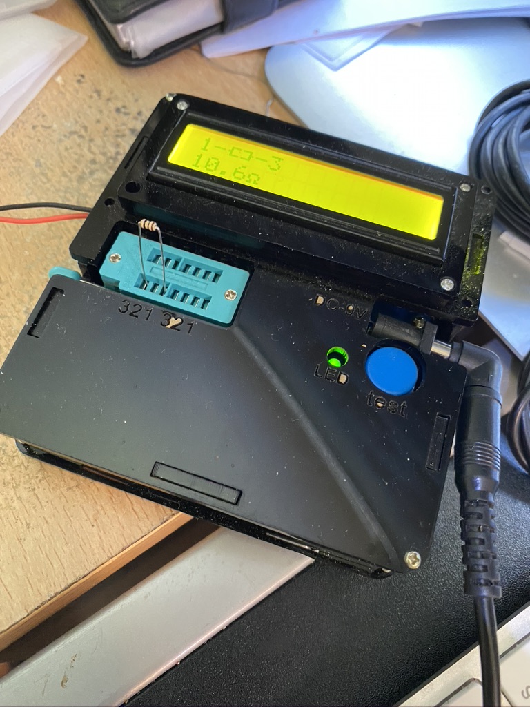
Its a long weekend here in England (Friday and Monday off work) so am starting on the Kanga DX Conversion Kit. I’ve bought this for when I can have my practical assement as part of my Intermediate Radio Licence.
Stage 0 has been getting enough practice and all the other pre-reqresuits ready, of course these are not in the build instructions, but faciliated the purpose and ability to build and test once complete.
Setup Mast to Receive on 40m – DXCommander
Receive Morse on TS-690 on 40m
Build up soldering skills on other kits (Volt Tester, Oscilliscope, Frequency Generator, Frequency Counter)
Lab Equipmemnt – have added a USB Microscope as I think this will be very useful
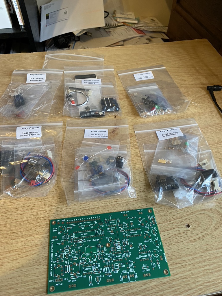
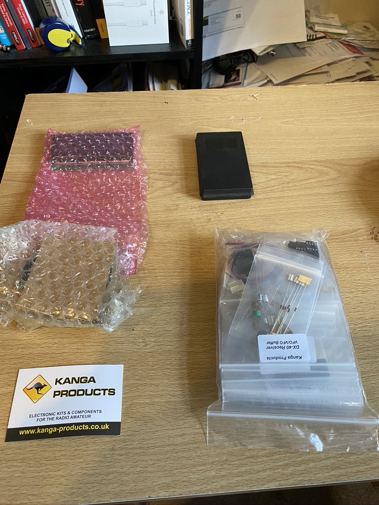
With that I laid out the kit and also pictures of my details so when the assement comes, they can see I have actually built the kit.
very nicely bagged components
screen, speaker and chips
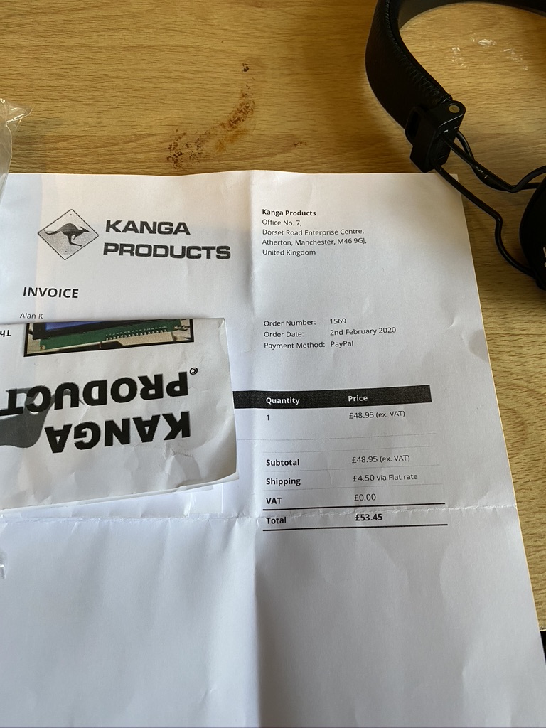
£53 for a kit…
How it comes out the box
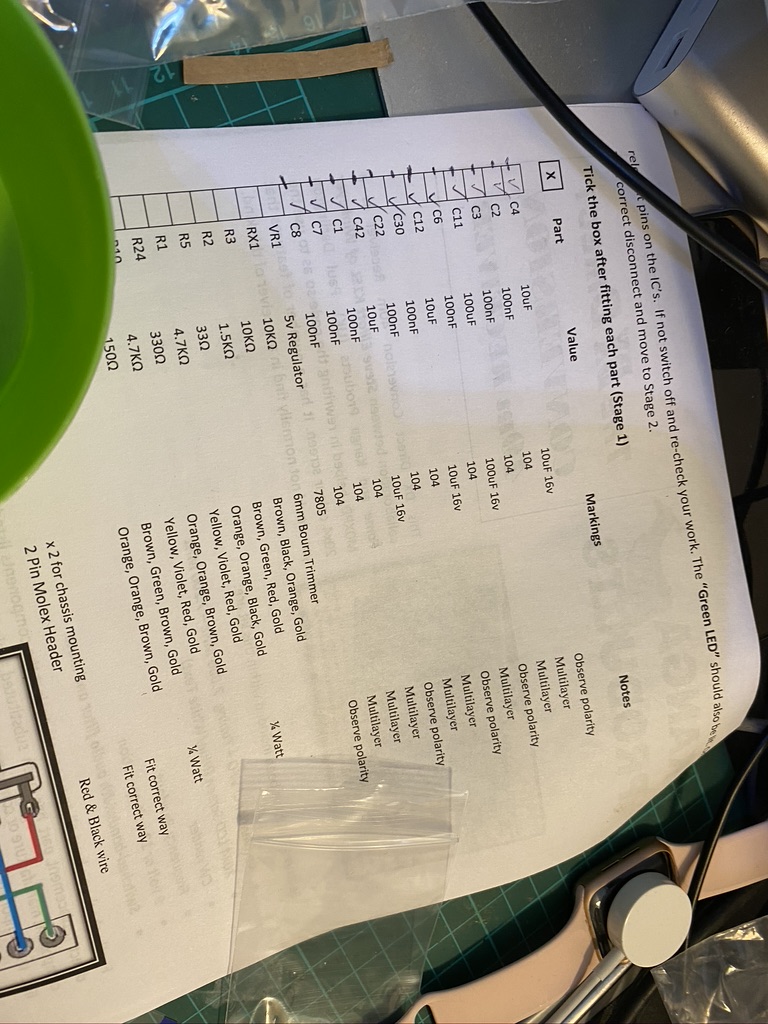
I printed out the instructions from here which are practical, but one criticisim I have is there is lack of a circuit and block diagram. As this kit is built for radio amateurs I think that should be included.
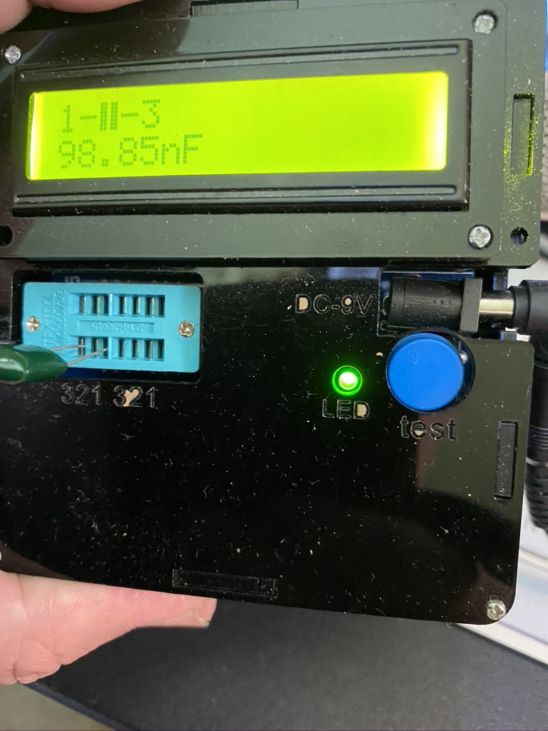
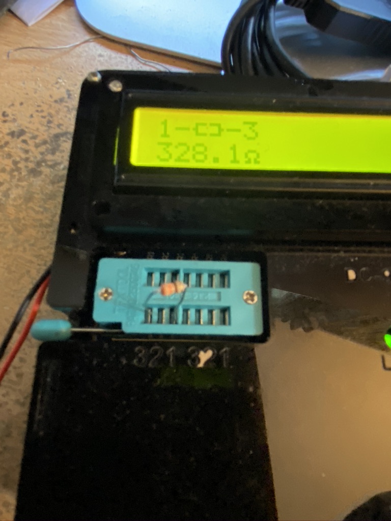
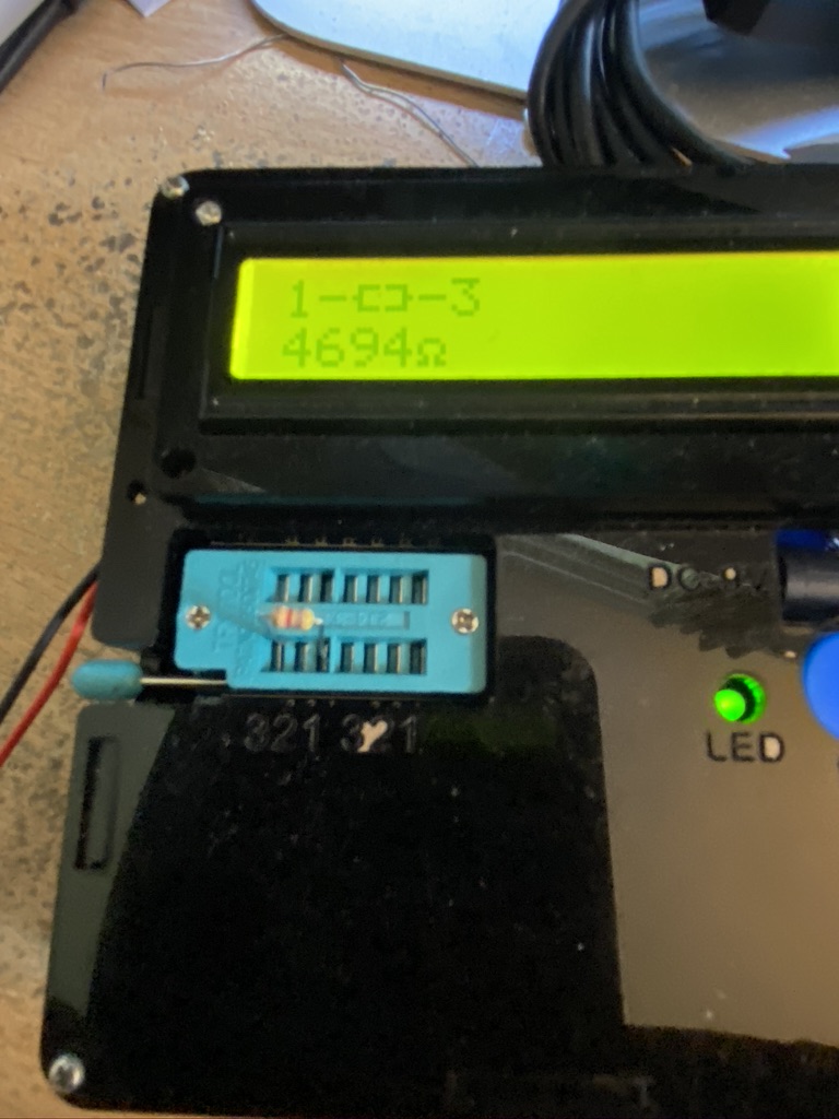
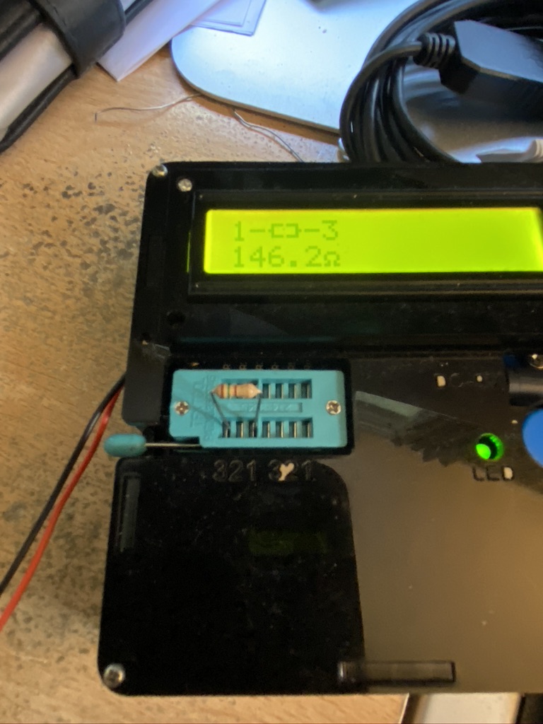
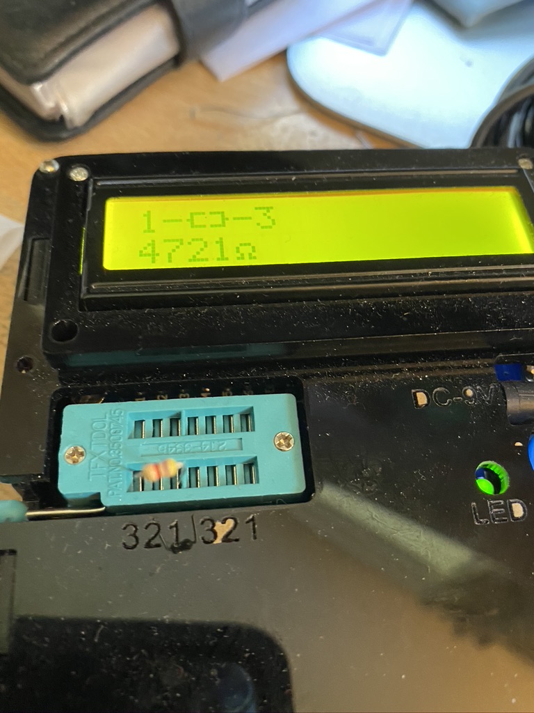
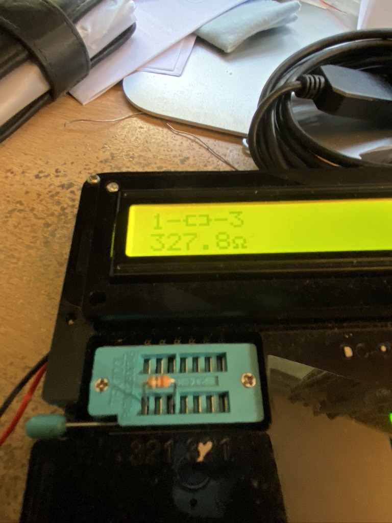
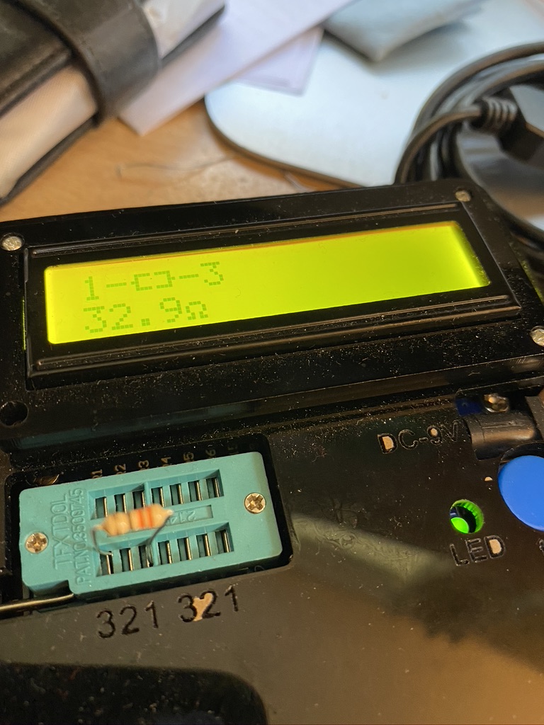
I was very impressed with the clarity of the instructions, in particular giving the colour codes for the resistors. As I have a tester I used that to confirm the values, but it is a great way of ‘learning’ the resistance bands.
checking off the list
check list and verifying resistors
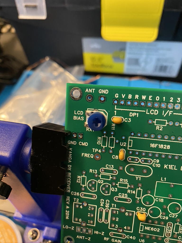
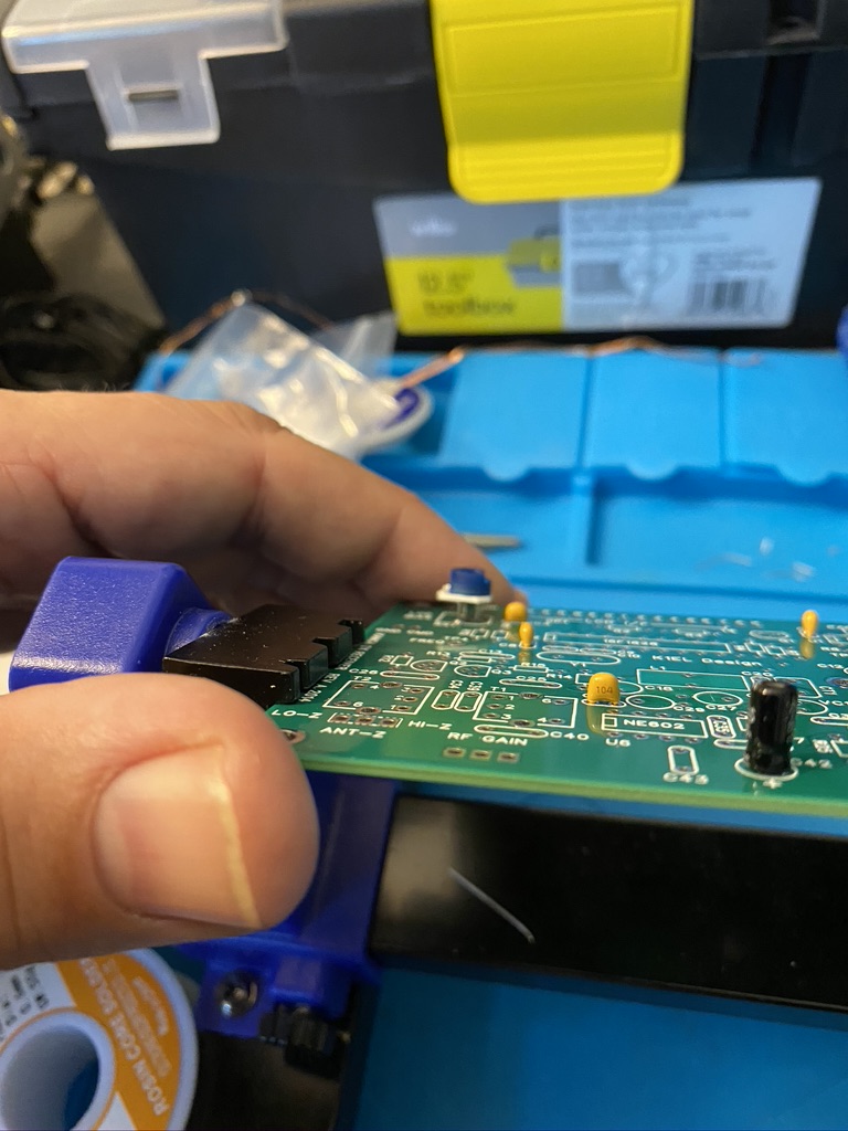
I found getting the trimmer ‘RX1’ to be quite fiddly, as it sits a little off the board and the ‘legs’ bend in a little. Using a fine pair of tweezers allowed the legs to be put into place with the correct height adjustment.
fiddily
tweezers required!
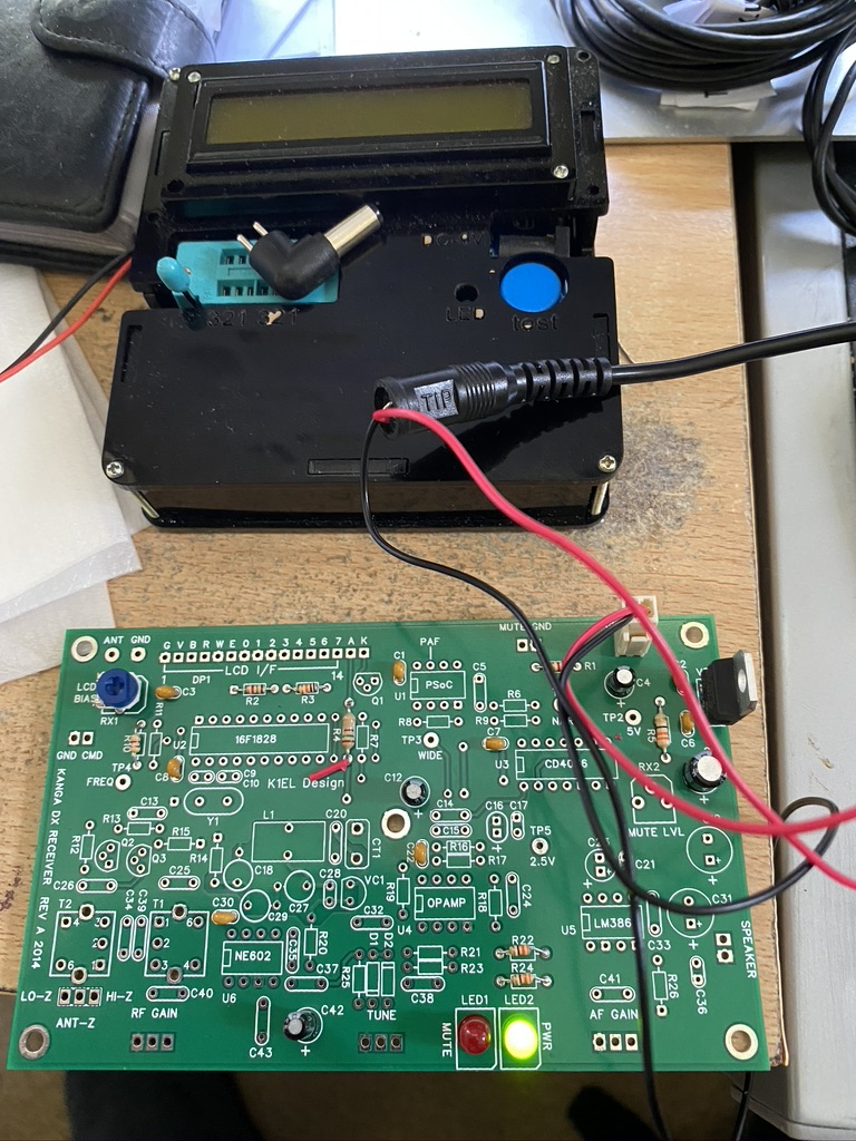
I then set about putting the LED’s in making sure that I got the +/- the correct way around. I used this site to confirm and from the markings on the PCB assume the ‘notch’ edge to be negative/flat as per the picture.
its alive!
It had taken me about 2 hours of patient and methodical building to get all the components in. I did find however that *ahem* someone had left the voltmeter on and the battery had run flat. I popped out for my daily ‘essentials’ hoping to get a PP9 but no luck, so have ordered a pack of 8 from Amazon here. In the mean time i adjusted my variable PSU and hooked the stage-1 completed board up and huzzah – I have LED’s – which i think confirms the power circuit is working correctly !
My next mission was to get the 40m band working. This is a very popular band and has so much on it, CW, Data Modes, Voice, so being able to receive and send is my objective on HF this frequency.
The previous SWR readings gave me confidence that the cable wasnt that far out, and for sure, it only need 6cm adding, so as I had measured I set about adding 6 cm of cable.
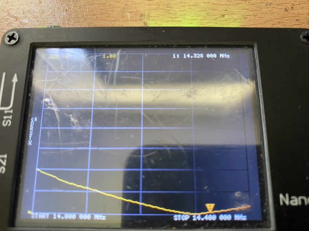
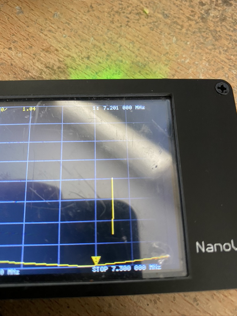
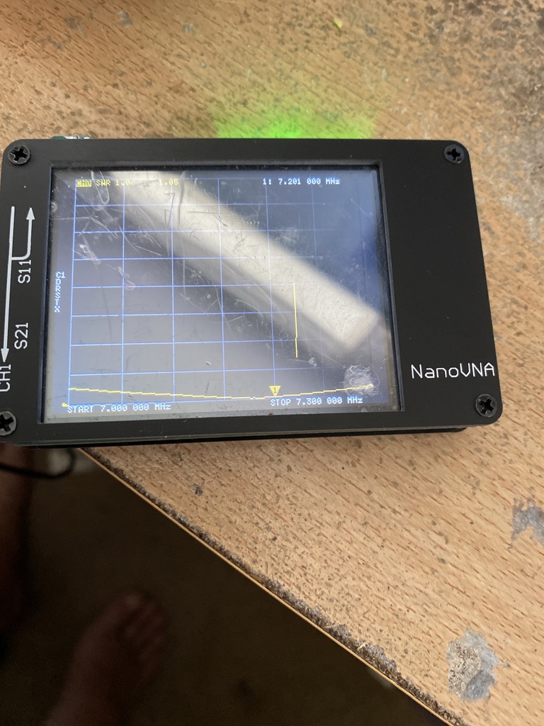
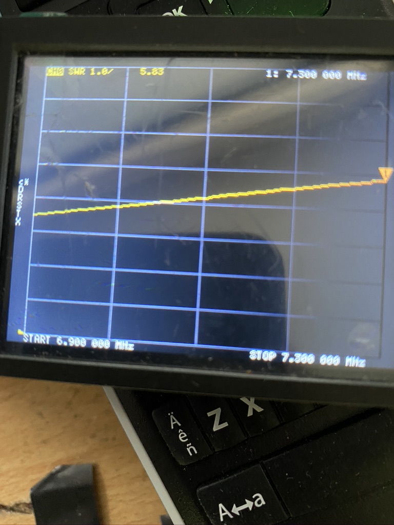
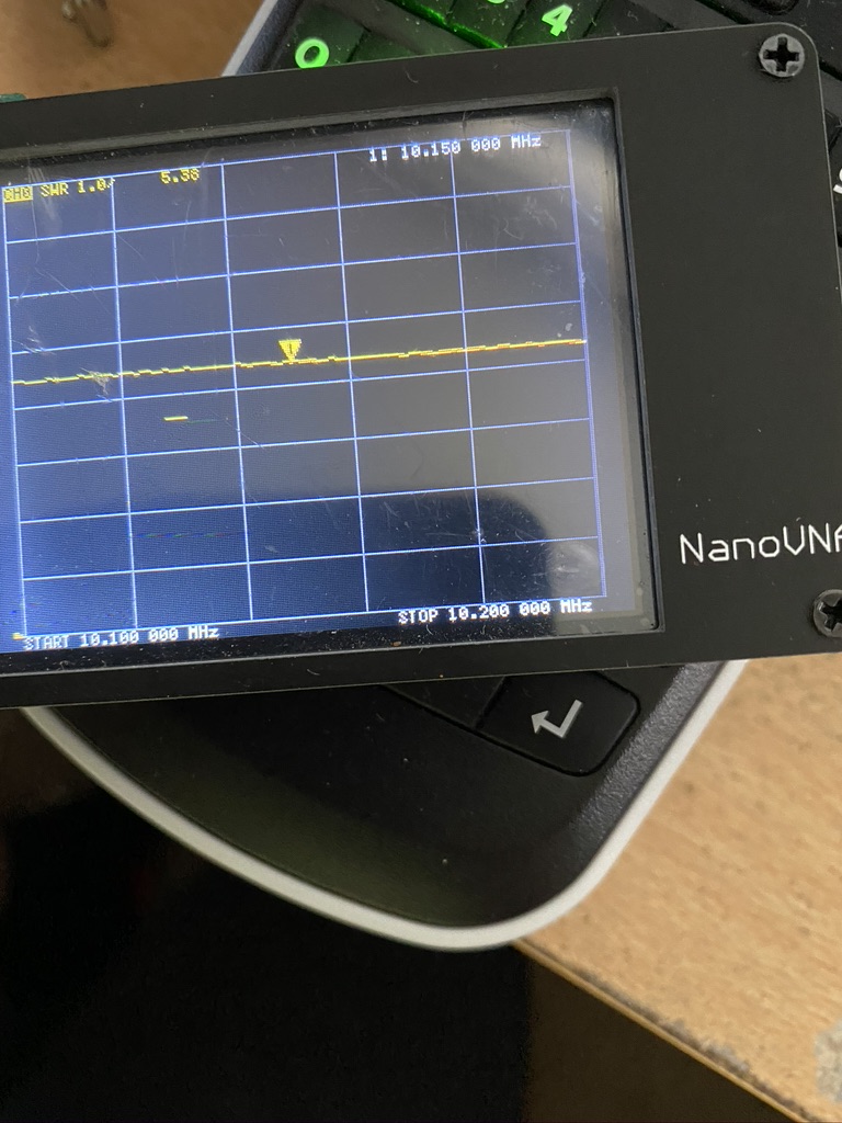
After taking down, re-erecting I am pleased with the SWR report from the NanoVNA (i done the recalibration just to make sure !)
1.04 SWR on 7.2Mhz
It really was worth the effort to get such a great reading – my buddipole setup could get down low, usually around 1.7~2.5 reading, good but not as good as this !
I hooked up the mast to the Kenwood and the amount and strength of signals was staggering (at approx 17:15 BST) – as I understand it 40m is a ‘daytime’ frequency for its best performance.
nothing about 1.5 for the entire 40m frequency
With my battle for low SWR being slowly won, I now have to listen, and listen alot to operators to see how they communicate. I cant wait for my first QSO, but know this will be harder than my 2m setup !
I have two more wires to go, but with 40m and 30m (the longest wires) I’m confident I can get the other frequenices all finely tuned before the week is out !
So its been another lovely sunny day down here in the QTH, but with a full day of work means a few hours in the morning and a couple in the evening to get things sorted.
Having done my analysis yesterday, I set about checking the mast. Whilst long winded, I had to be pragmatic and methodical in my approach to ensure progress was made.
take mast down
remove all wires
measure wire outside with long tape measure
compare to instructions, correct as required
mount and test
repeat for each wire
So having yesterdays results I took the mast down, which wasn’t too bad on my own given the mast is so light and guyed relatively low (well compared to the 2m/70cm mast which requires steps just to start! I disconnected all the wires, which was quite quick, then set about measuring the 30m wire.
With the accuracy of laying flat outside there was some 40cm of wire missing, so i cut some, re-soldered back on and reconnected, then re-erected the mast and radials.
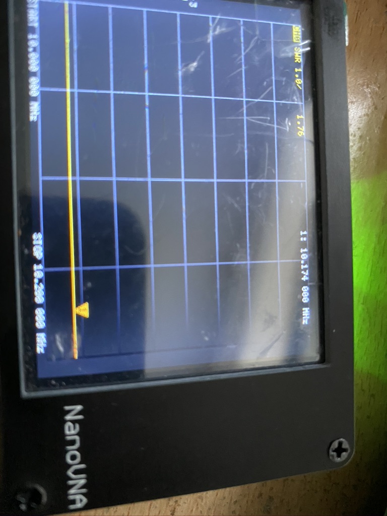
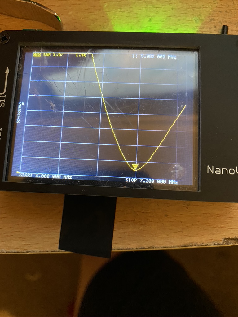
I returned inside for testing with the NanoNVA – SWR still 5.5 – agggh ! What had I done wrong ?! so i went to check the basics, like connections,etc. All good there. I then tested the NanoNVA against the 2m antenna, SWR is fine. Then i though, could the other mast effect the DX Commander, surely not, but to make sure kept flipping the tester between antennas.. then it ‘hit’ me.. maybe i should recalibrate the NanoNVA for 30M. I set about doing that then…
30m – 1.76 SWR
Huzzah ! So, it maybe that I need to recalbirate for each frequency, or may not, anyway, to rule that out going forward thats what I’m going to do so the step plan becomes.
take mast down (leaving known good wire on)
measure removed wire, make corrections as required (lengthen/shorten)
re-measure wire to confirm length
attach to mast and erect
test previous frequency is still working on the correctly
re-calibrate NanoVNA for new frequency
test
Hopefully I will get the 40, 30 and17 completed today now i have a method, but another busy day of work is about to begin !
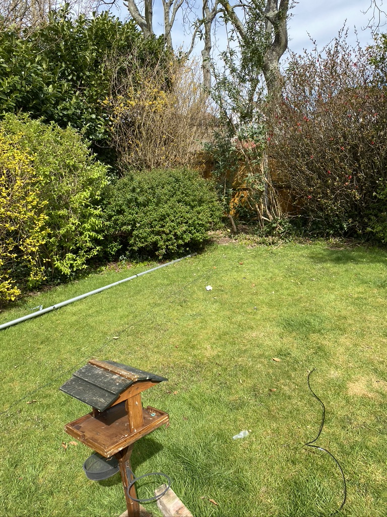
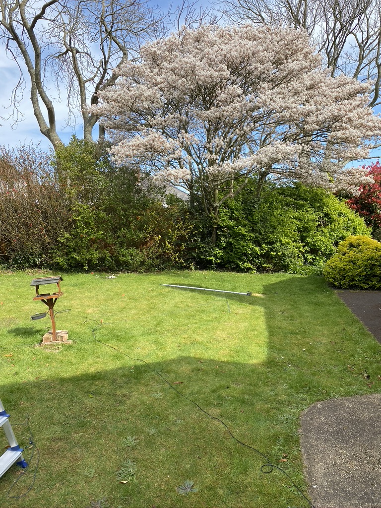
So day two of the DX Commander started with a few more things to build/cut indoors (radials & pipe clamp aqua tubing) then it was off outside to the garden. It is a really glorious day outside, and Covid 19 is still with us. I feel very lucky to have a nice garden to work in and do my amateur radio pursits !
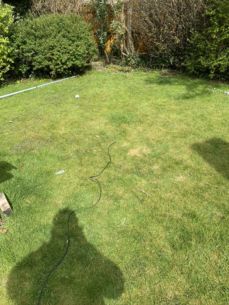
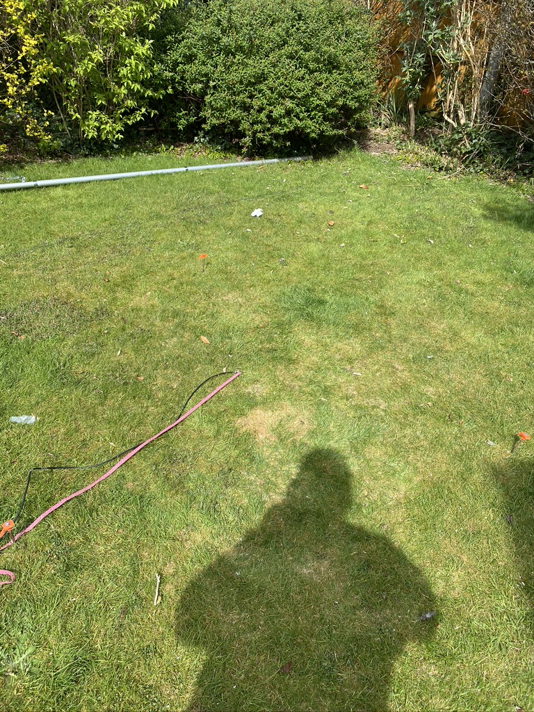
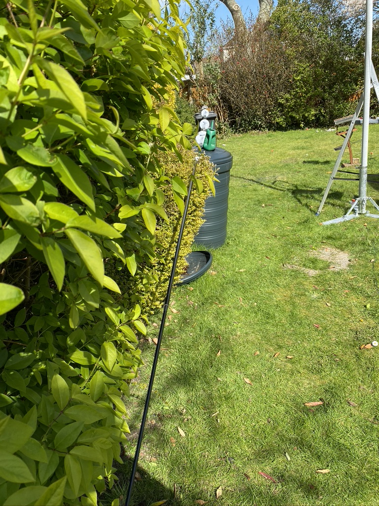
I started off with taking the coax from the ‘shack’ to rougly the area I wanted to install the mast. At 30 meters long, there distance from the shack on ground was good, and once roughly in place could do a saftey assement before going further (overhead cables, what-if scenarios, area is clear/tidy already, aware of other mast/guy ropes).
Once I was happy that I could work safely, i then set about putting the guy rope stakes into the ground, in this case some heavy duty tent pegs that I have used both on my buddipole and rather large 6 men tent (this should be going up this week to help with us going outside safely). It was time to unfurl the full length of the dx commander !
ground
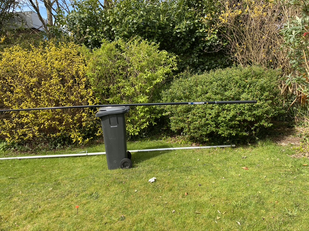
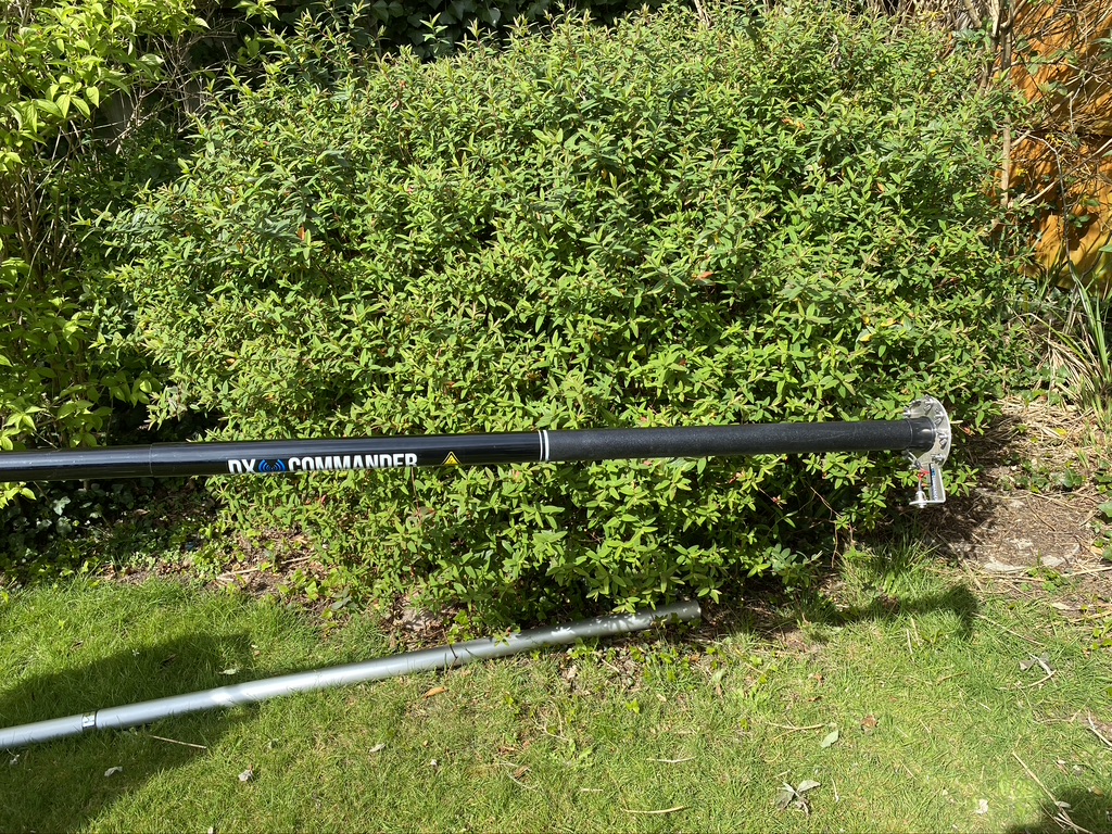
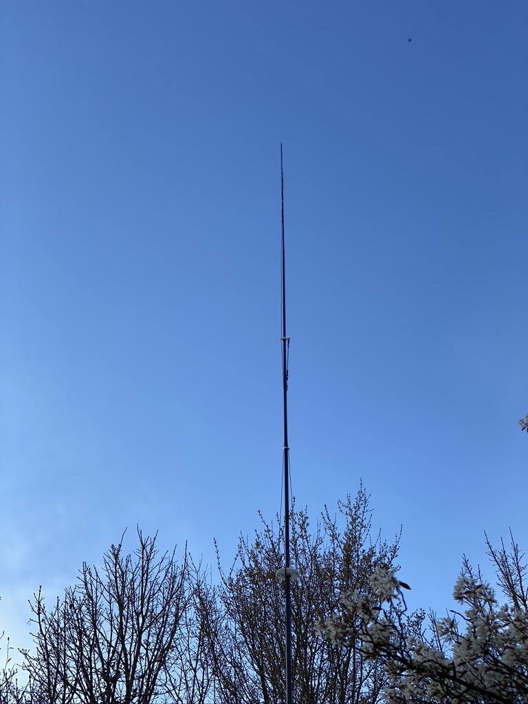
full length – 10 meters of pole
a very nice base and good saftey sticker
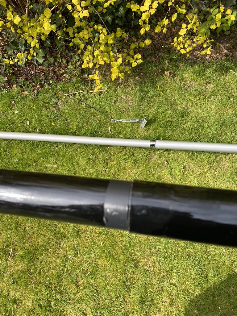
applying tape to stop water ingress
Once the dx-commander was extended and lock, and it is a very good lock action with a sturdy ‘twist’ on each section, i put electrical tape on each join just above the lock. I think this has two functions 1) stop rain water from getting into the lower section 2) protect the fibreglass pipe from the clamps.
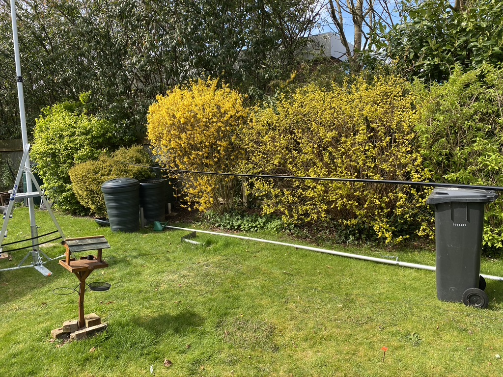
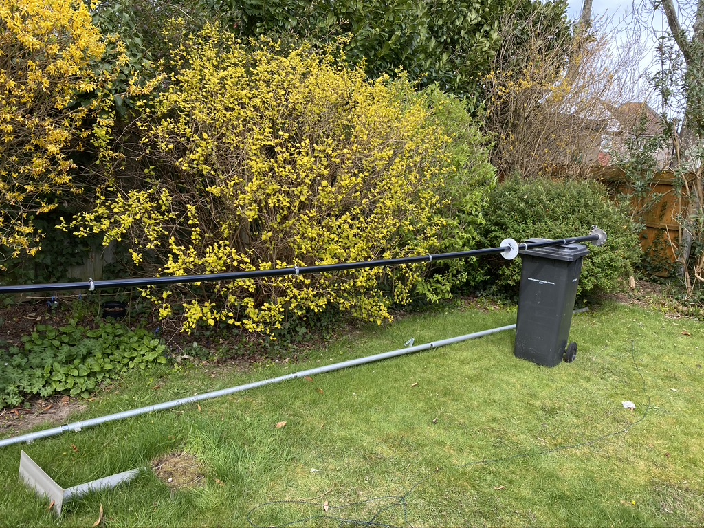
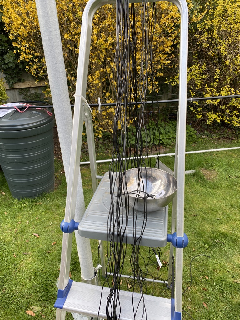
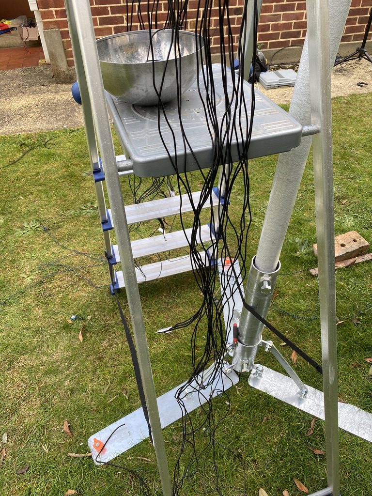
I used a wheelie bin and water vat to support during the build – to start with just putting it on was good enough, later i put some bricks loosely around the tail end (base) to help.
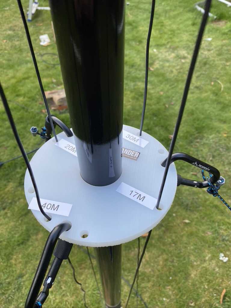
Installing the ground and feeder pipe
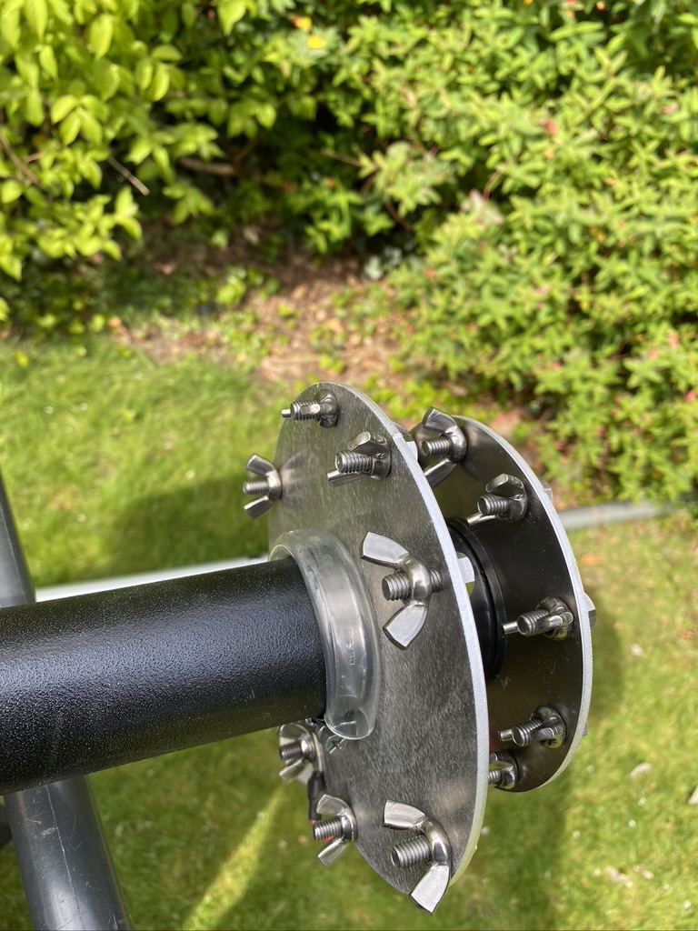
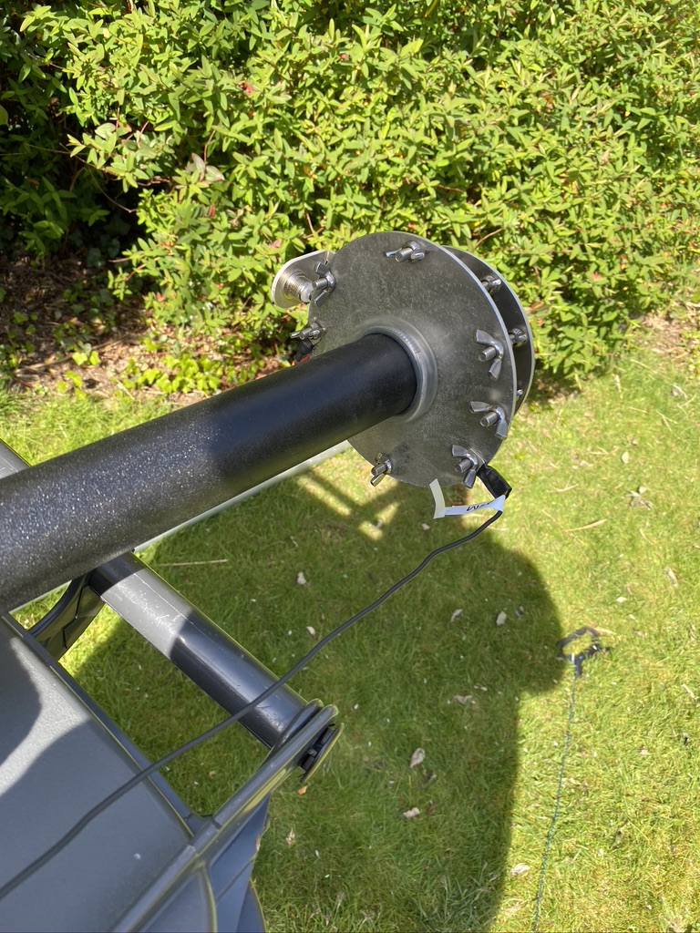
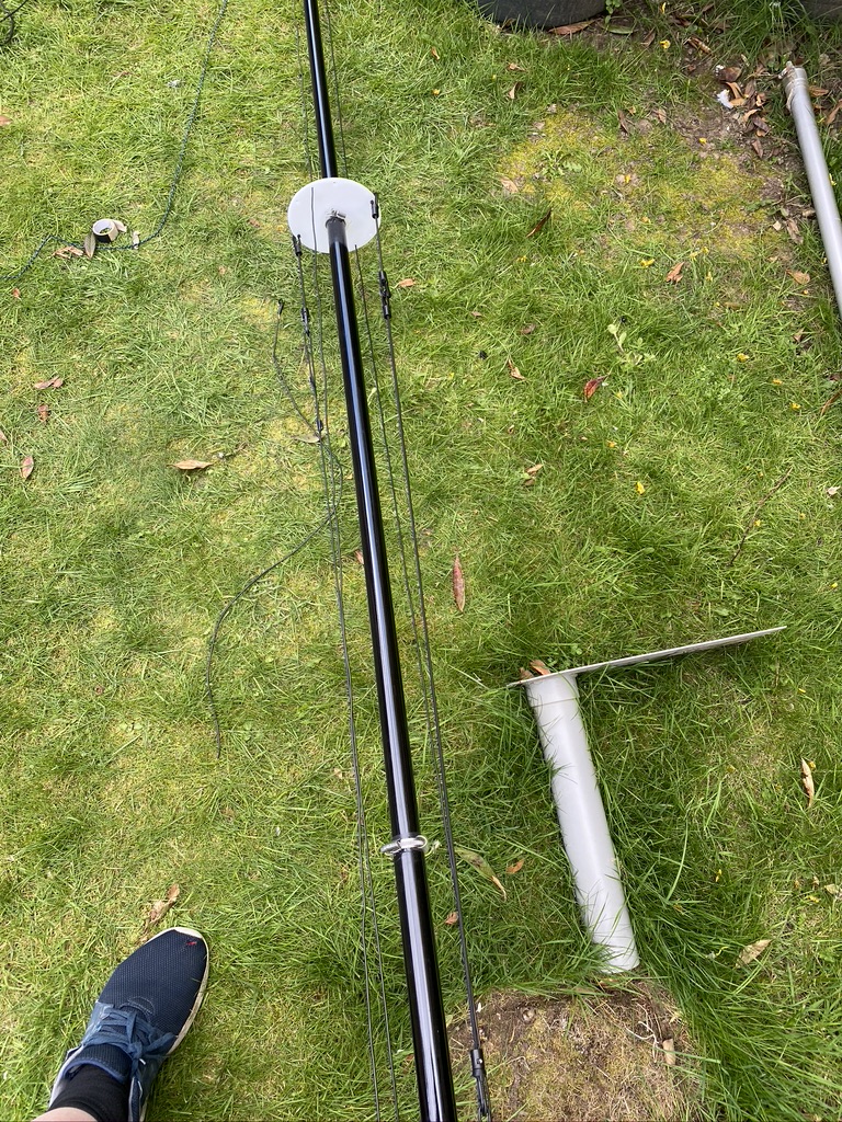
The guying plate
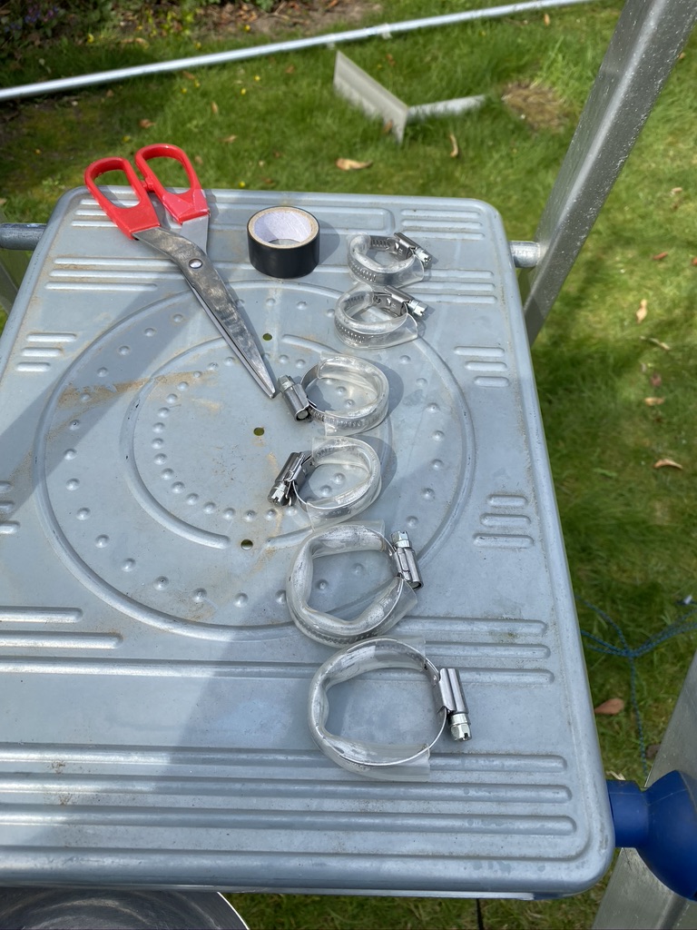
jubilee clip in position
various jubilee clips
clips in place
observing 2m/70cm with a gust
loving the garden
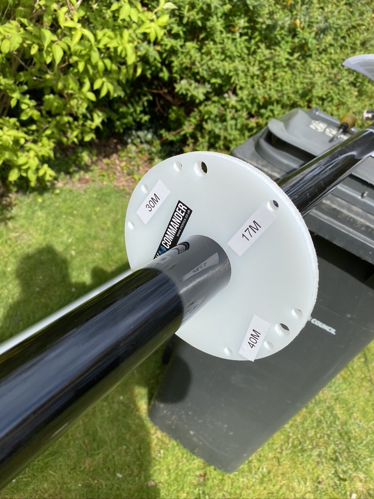
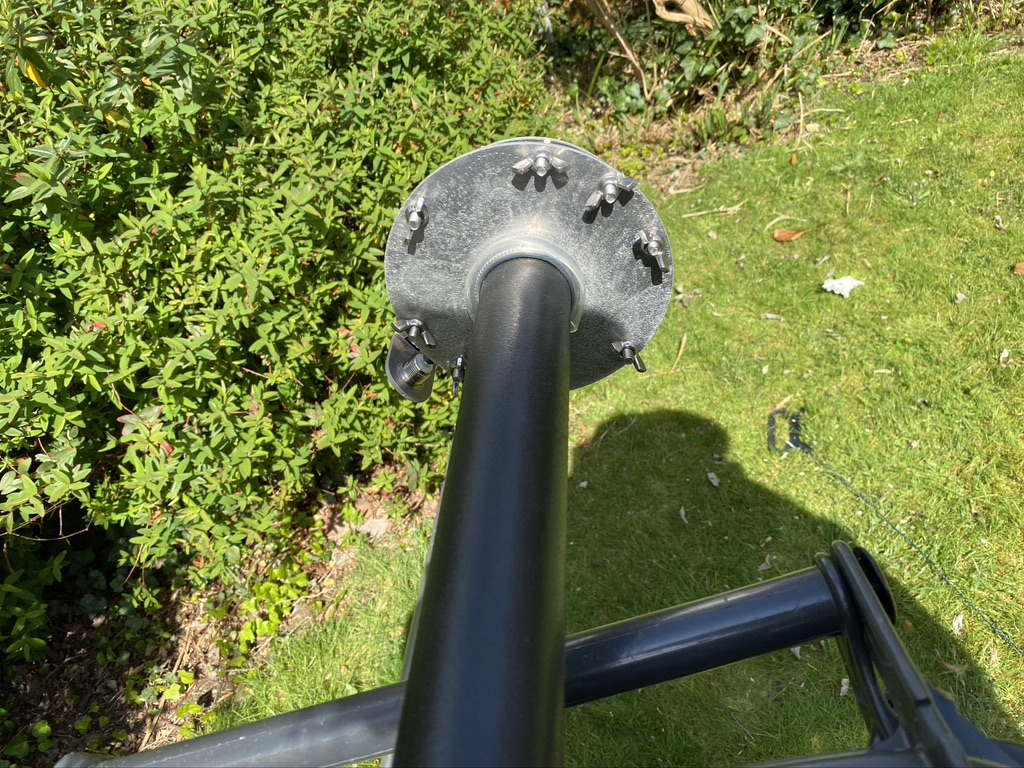
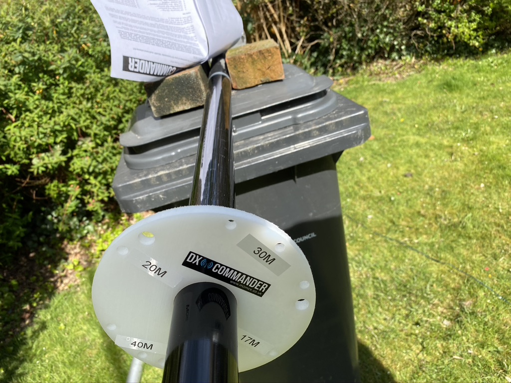
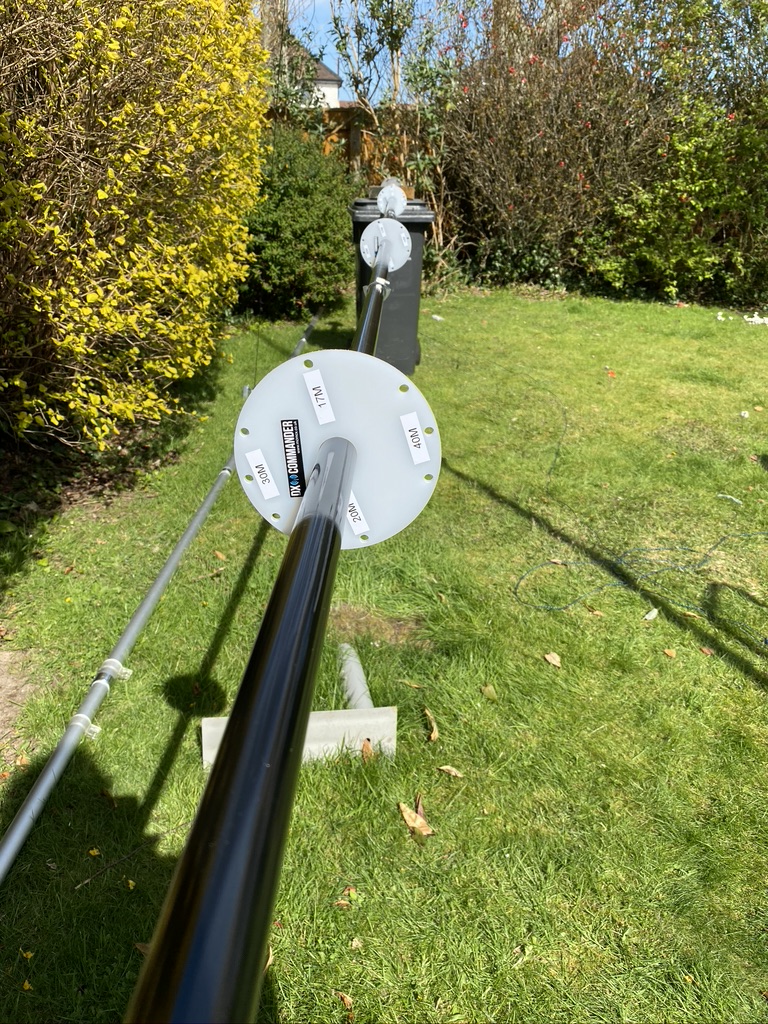
I then set about attaching the plates for connecting the radials and verticals. This simply screws onto the bottom. In hind sight I should of labelled the initial feed points for the verticals as well, maybe something I will do post-install when i start tweeking and get basic operating working.
I had pre-made the jubilee clips and soaked them in warm water. Whislt the lengths are given in the instructions, i just went for broke and made them so they fitted, i was happy with the results ! On a personal note, i really dislike jubilee clips, they are fiddly and usually try to find alternatives, in this case tho they do look to be the right part for the job, with the tape and aqua tubing (good idea Cal!) and careful tightening would be ok.
With the pole extended and it starting to take shape, i had a break and enjoyed my surroundings, including the breeze and how well the 2m/70cm mast was doing, it really is a great mast (still need to write the write up of that…) The garden is starting to come alive with srping and the warm weather, it really is a lovely place to relax.
installing the guiderplates
verifying the locations
pre-cut lengths
really should of labelled…
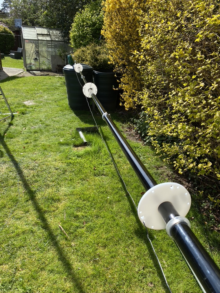
guying disc
the first vertical!
more verticals!
we are getting there!
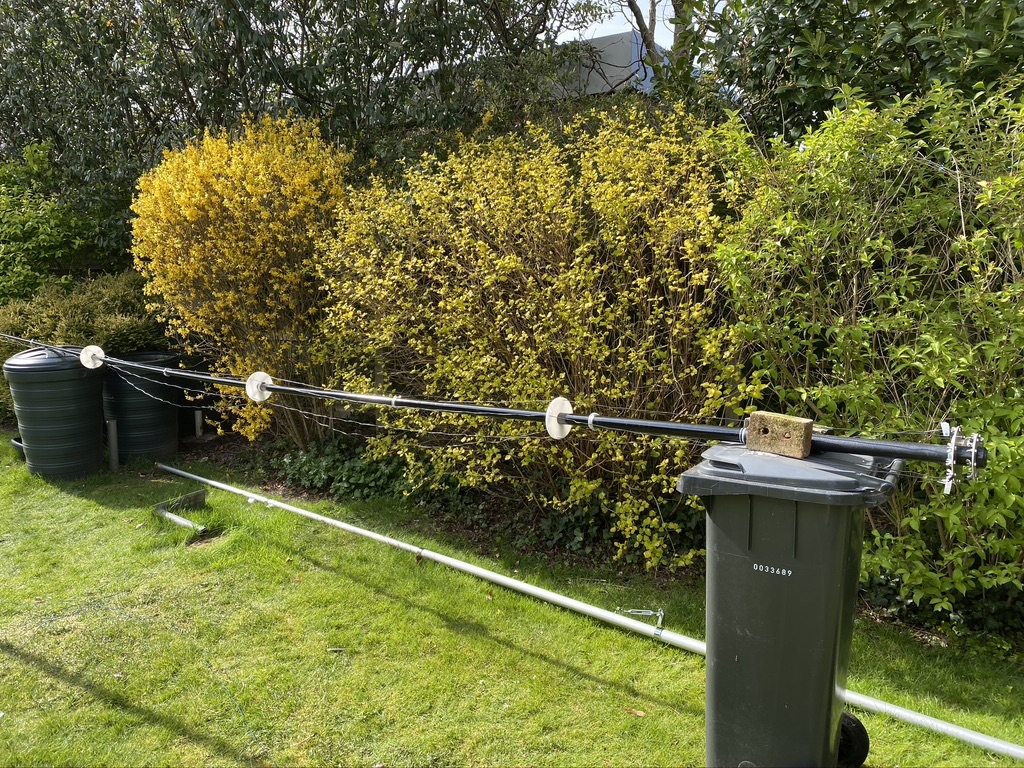
now with added brick
installing the vertical
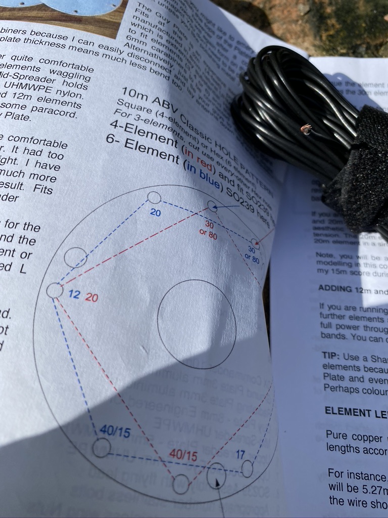
It was now time to start installing the verticals – whilst I had taken the time to label the guide, i hadnt done the plate, but the documentation is very good, so i refereed one more time to my print out. I had the lengths already pre-cut and labelled, although I would find out later on the ‘M7ALU wire cutting factory’ QA processes needed some review !
I feed 40m and 30m thru first being the longest and using electrical tape as needed to keep it in place ‘just for now’. I did have to undo the jubilee clips and put the guiding plates on correctly once more, but no big problem there ! I added some bricks for support to (try) stop the mast rolling off the bin.
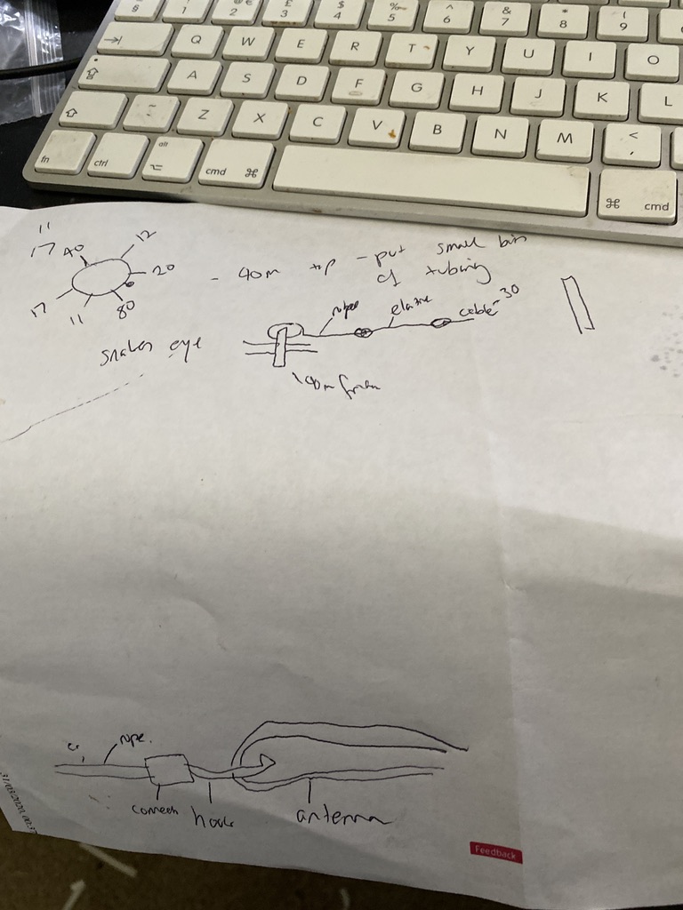
scribblings
Looking for missing cable
cor
hmmmm
somethings not right…
installing the paracord and elastic
So with the verticals fed thru it was time to mount them. I read the instructions a couple of times but was still struggling with getting the penny to drop, so headed indoors. I watched this excellent video to get some help
great section on how to install the verticals, great video overall !
With that I made some scribblings and had a better idea of how to use the supplied clips, rope and elasticcord. But where was the elasticcord.. I checked the list, yep I had checked it off, but I could find it no where, several times of going in and out I couldnt locate it ! I then thought, well, where did I last see it, then went back to my photo album on my iphone, there it was, i knew what i was looking for at least now ! So.. one of the things that happens is that I look for stuff, and cant find it and its actually right there in front of me – this was the case here ! After going in and out 3 times, i found it, unfurled, but exactly where I had left it ! Hidden in plain site, or just stupid.. lol.
I set about cutting lengths and using some of what i had learned from the video, it then struck me that the lengths of the lower verticals were almost identical.. .hmm, thats not right ! So i set about remeasuring with them taught and in place. Yep, sure enough I had added 1 meter to many to 17m ! I measured several times, then cut once more – perfect (he thought..) and attached the cord again, now that looked better. Suprisingly 20m was cut perfectly, even with the fold over !
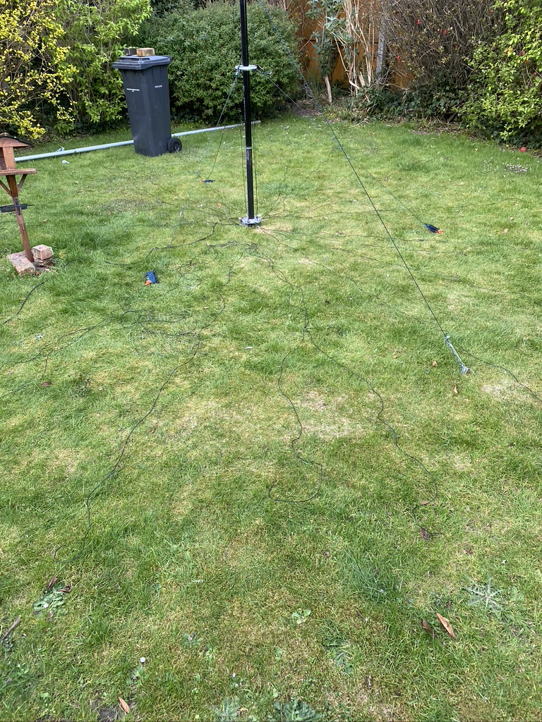
radial rat nest
radials on a stair way to heaven
time to test ?
radials and time to test
I remeasured 40 and 30m, 30m was way off by another meter, so cut that to length again, then made tight with the paracord and rope. Once understood this is a really great system and keeps the verticals very tidy on the mast (he said…).
With that I brought the radials out and got them kind of tidy on the stairs, ready for attaching once the mast was about to go up.
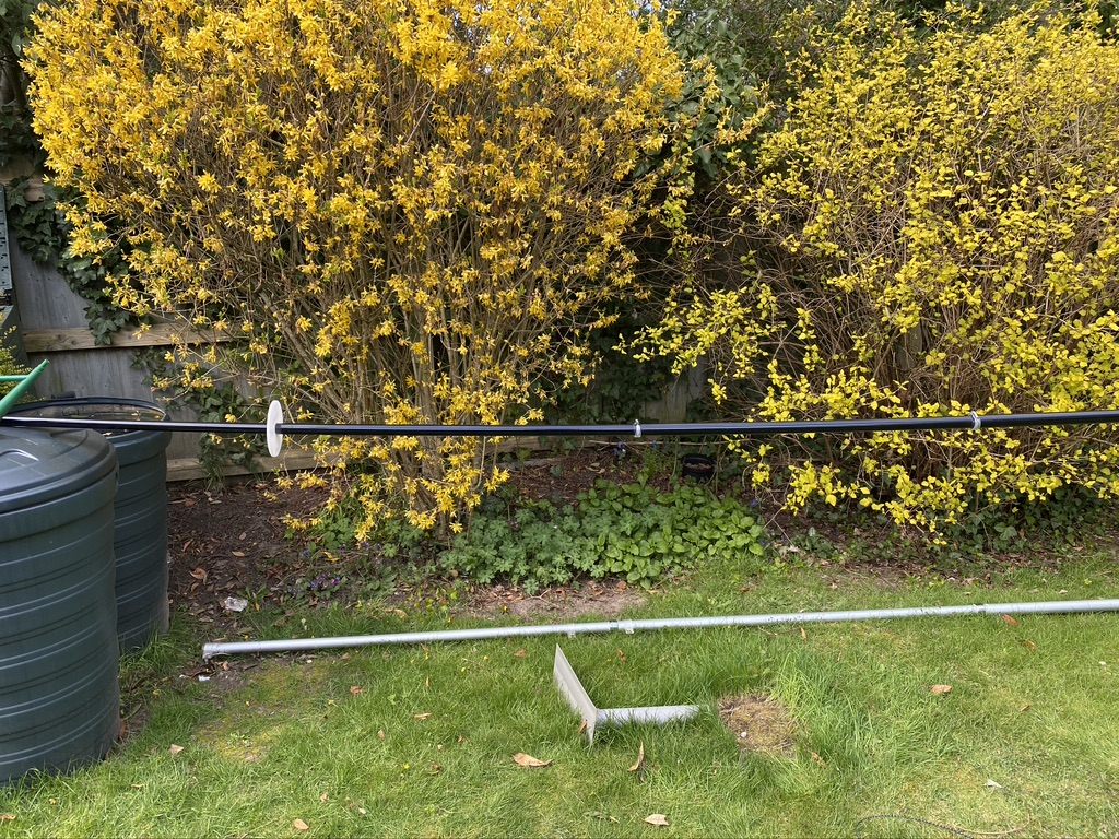
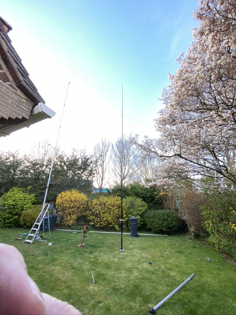
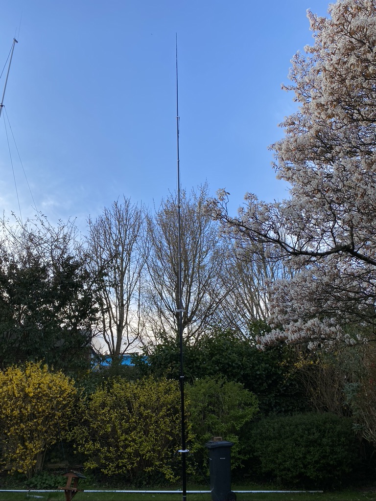
UHF/VHF and HF masts
The DX Commander!
An impressive erection
Guying attachments are tight, super easy bearly an inconvieance
radials are a pain in the a…
The DX Commander – a fantastic erection
With the assitance of my son Paul (who was playing some lovely tunes, not too loud, and heavy enough to enjoy) we go the mast up. The mast is very light, even with everything on it, but having two peole very much helps with health and safety aspect of the installation until the mast is guy’ed up nicely.
So with the mast up, it was really great to see it looking so good. Paul and I admired the view of the mast, whilst I was observing the effect of the wind and ensuring the guy ropes were doing their job correctly ! Everythign in physical construction worked really well, and don’t mind saying felt quiet proud of getting to this stage ! I attached all the radials, having dodgy knees and a hip these were phyiscally quiet a pain to install, but nethertheless, was easy enough. I can see why more permenant installations have these underground though.
With everyting in place it wsa time to start the analysis ! I did say to Paul before hand, if this works, it will be like the oscillisope, a minor miracle – as there are so many components that could make it not work..
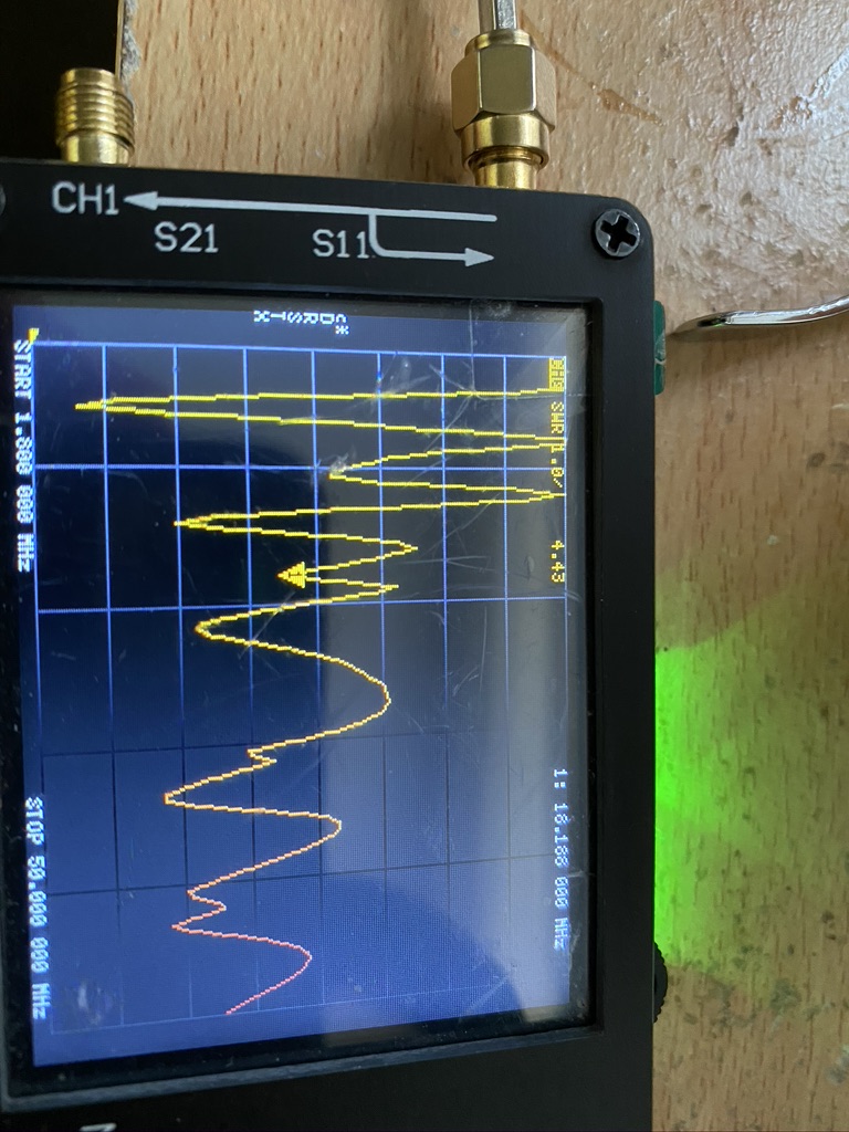
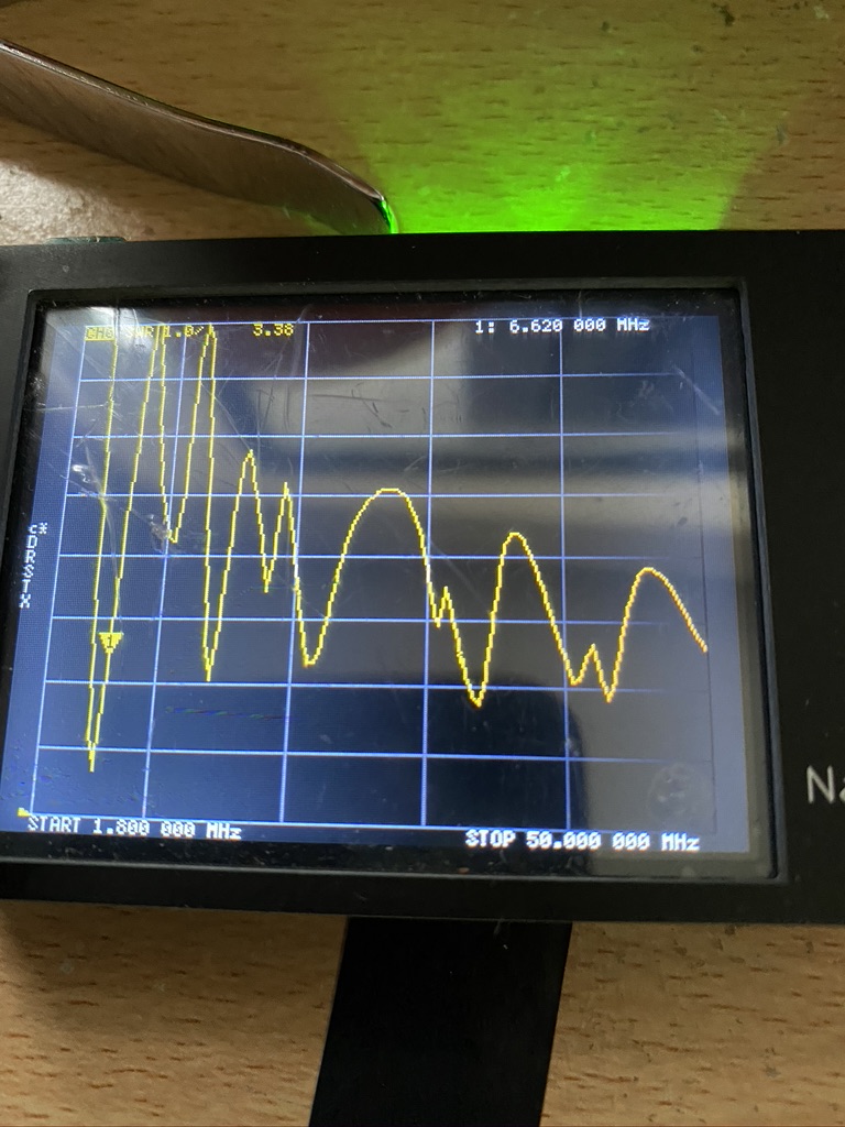
full range scan
Initial reults
So i connected the NanoNVA to the feed wire in the ‘shack’ and as half to be expected the results on the amateur frequncies were quite some bit off. I also noted down the frequency of where the lowest S.W.R reading was, as this can guide in where the issues are.
Frequency (Mhz)
S.W.R Result
5.656
2.17
10.476
5.14
14.332
2.95
18.186
4.42
21.562
3.17
33.612
2.85
43.252
2.46
lowest SWR readings and associated frequencies
I then tuned the VNA to the amateur frequncies and recorded the midway S.W.R. reading, 20m could be useable for putting RF up, but 40, 30 and 17 were a long way off being safe to use. I like the SWR to be below 3, but for me 1.5 is my target. Even with 10W I would probably damage something and probably wouldnt get out very well as most of the RF power wouldnt be going into the elements.
Meters
Mid Frequency (Mhz)
S.W.R
40m
7.1
5.4
30m
10.15
5.6
20m
14.2
3.01
17m
18.11
4.52
Amateur frequncy SWR readings
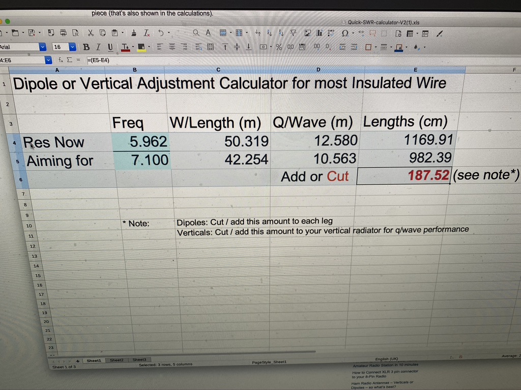
The excellent DX Commander SWR spreadsheet
With the data in hand, i went to use the excellent DX Commander S.W.R. calculator to either cut or add. Unsuprisingly it was clear that I had too much cable on the mast. This spreadsheet really did make it simple when armed with all the correct data though, so thanks Cal!
I have noticed that the top 40m and 30m elements have become twisted around the top of the mast, so I will first untangle those before cutting to see what the results are like.
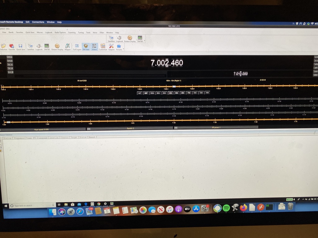
Not to be discouraged, i could still use my mast for listening and I could set about setting up my little Windows laptop to control the Kenwood via CAT control.
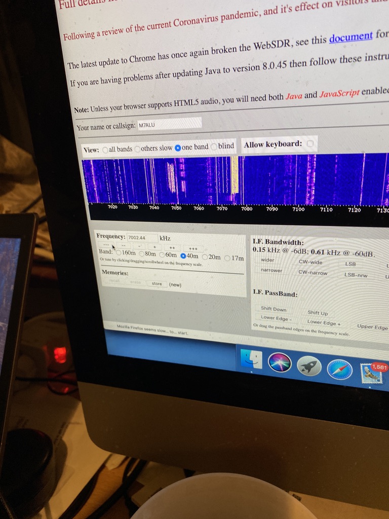
Compare to Hack-green WebSDR
Ham Radio Deluxe
Listening and compare to Hack-Green WebSDR
So there will be another day of tweaking and fiddling to get the SWR right down and there are a few more ‘final’ fittings to put on the DX Commander, but overall I’m really satisfied with the progress and just how good the DX Commander is.