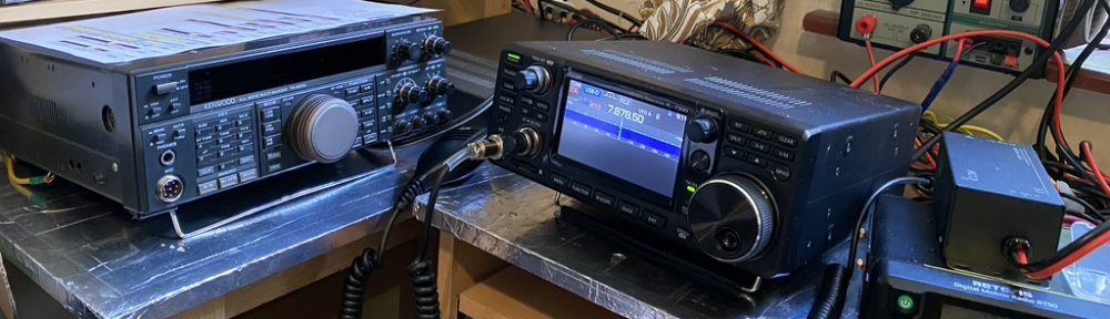
With the 2m/70cm antenna up and getting used to using the RT90 in UHF/VHF and DMR modes I can finally concentrate on assembling the DX Commander multiband antenna I ordered several weeks ago.
What is a DX Commander you say ? Well, it is a vertical multiband HF antenna created by Calum (M0MCX). I had been using my Buddipole in various configurations to use my Kenwood TS690S, which I dont mind saying, whilst rewarding took a fair bit of swapping/building each time. The DX Commander allows me to erect a multi-channle vertical which can be easily taken up or down, so suits my operating needs ideally, and best of all, its performance is amazing from what others and the numerous youtube videos show.
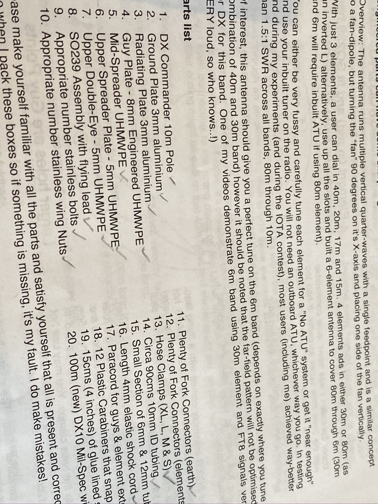
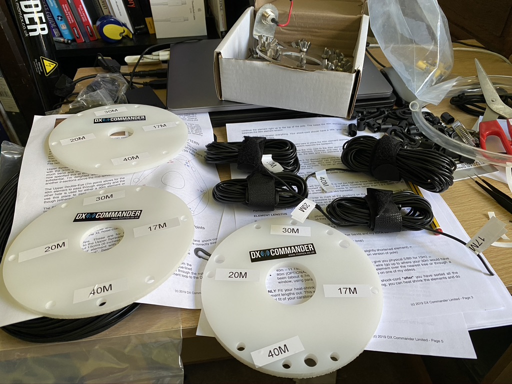
First off, check all the parts are there. When you get the DX Commander, it comes with a very nice (aesthtically at least) fibreglass tube and loads of other bits. Before even attempting to put this together, I printed off the instructions, read them, read them again – had a sleep, and read them even more. I then set about checking the components and am really glad to say *everything* was there. Of course everything should be there, but we have to consider that Callum is largerly operating this business as a family/his own thing – so all of the components are selected and packed by hand. Callum is a top guy and always says if you have an issue even with an existing part, he will do his best to help, thankfully there was no need to call up for any missing parts in this case.
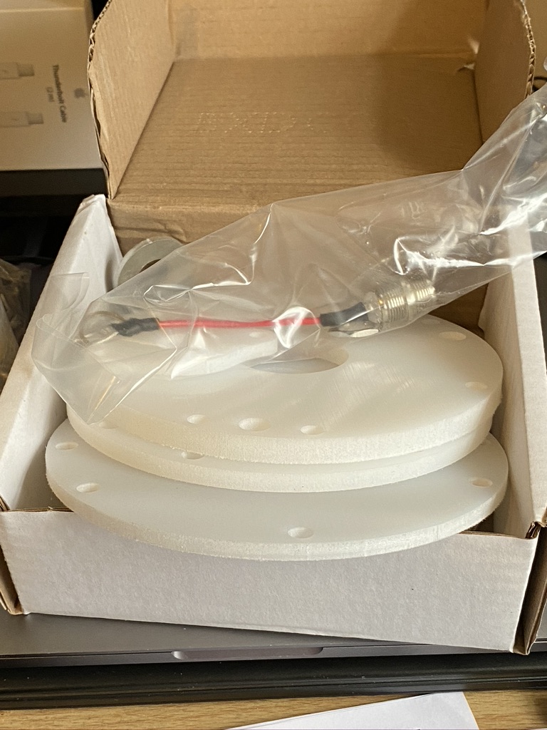
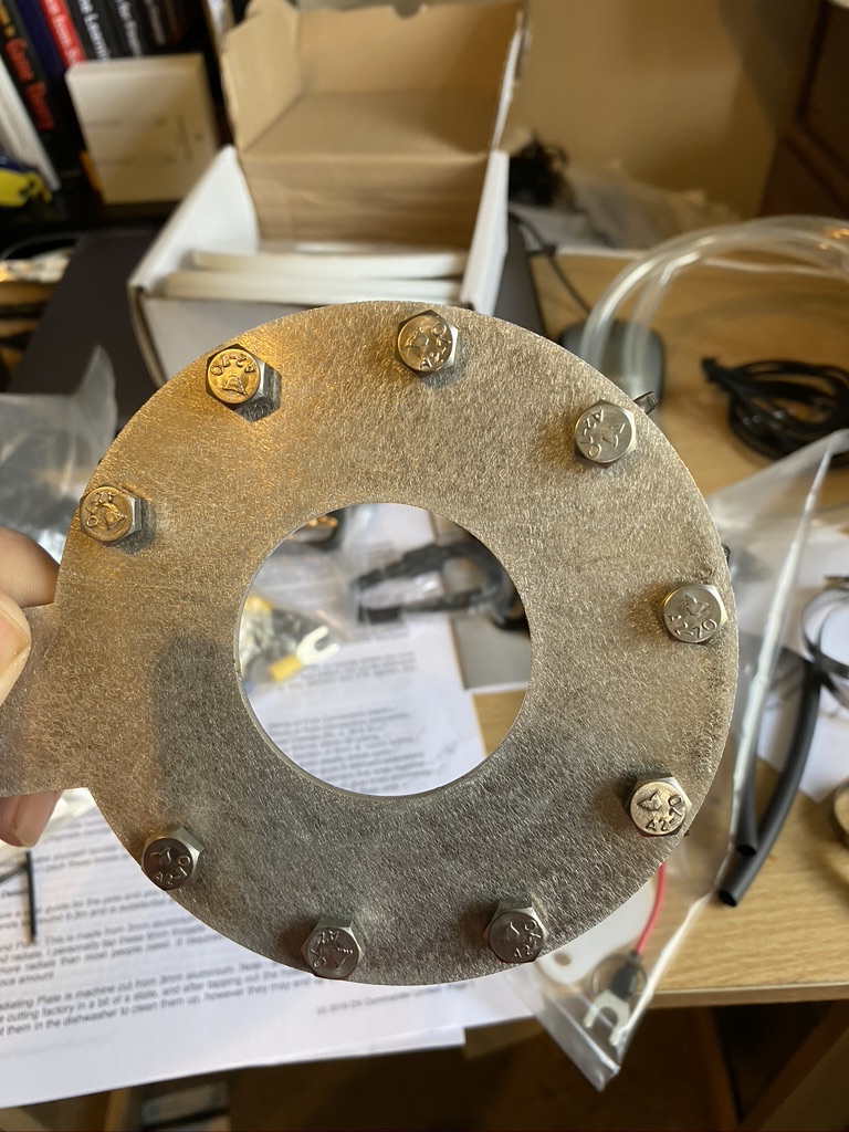
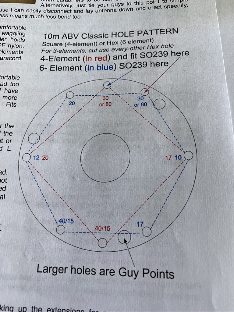
Next was to understand how the ground and seperator plates worked, I didnt do this to any specific order, r.e. instructions, but felt it was a good idea to see how these aligned. They are really strong bits of plastic and the holes are very well cut (no cracks/tension from what i can see !).
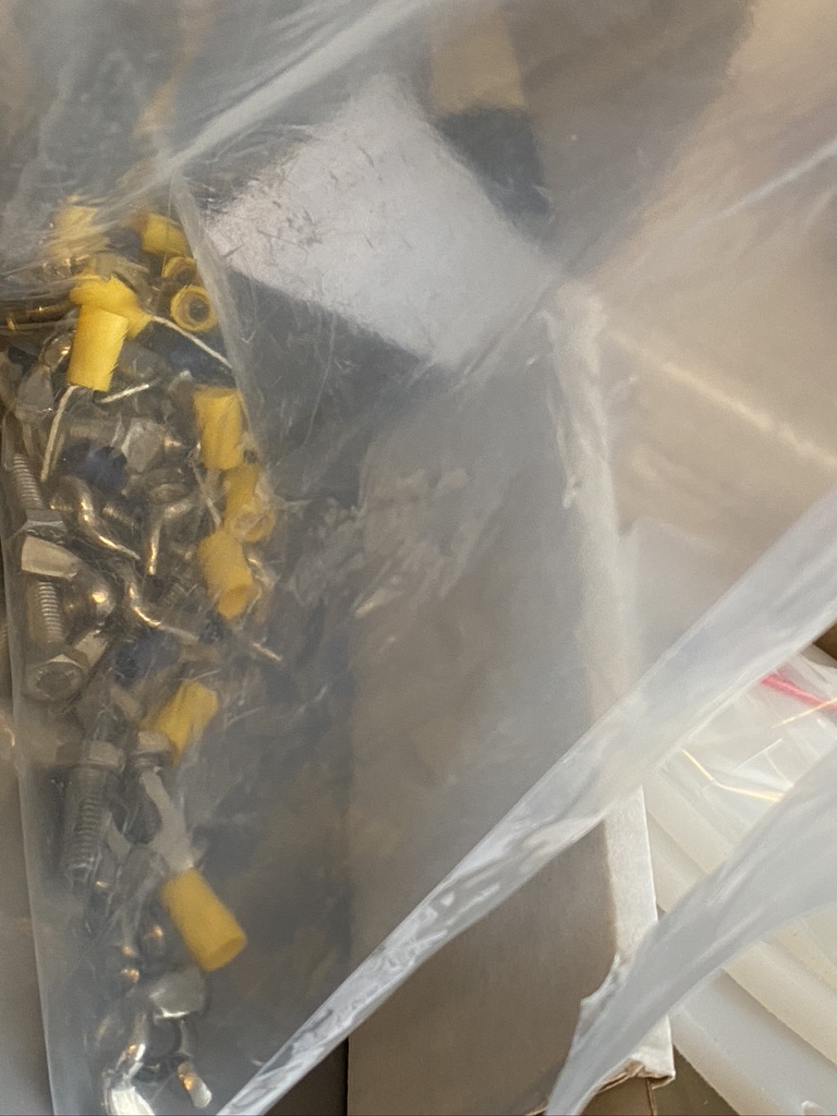
I then counted out all the screws bolts and connectors – again from what I could see good quality bolts and connectors. For the price, these are very good quality. The bolts give me real confidence that everything will be held securely to the base plate once outside.
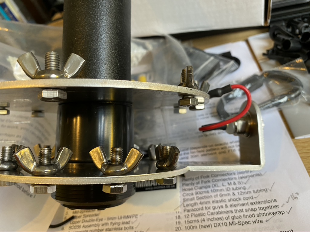
I then connected the ground plate to the bottom of the pole and slid the feeder plate over the pole to see how they would connect – have to say (again) you can see how well thought out the DX Commander is, its a pleasure to build and work with.
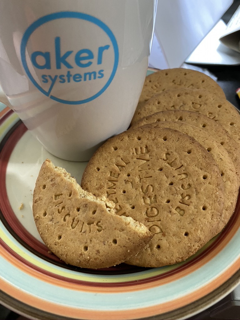
By now it was getting ready to do the next step – all the wires for the verticals. A cup of tea was required.
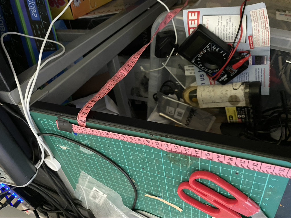
Now I’m not really used to making/measuring stuff, and wanted a good way of getting the right cable lengths. I do have a big metal retracable tape measure, but that seemed like overkill and owuld mean going outside to measure the wire. Instead I got my clothes tape measure (also use on Buddipole for whip lengths) and fixed a 1M length down. I then developed a process using a crocodile clip as a market to relibily measure the required distances. I measured MANY times before cutting, I can assure you !
With the desk setup ready to start cutting, I then had to decide on how many elements to set it up for. My main interest is 40m to start with, as 80m requires some additonal consideration, i want for the 20/40/17/30 option.
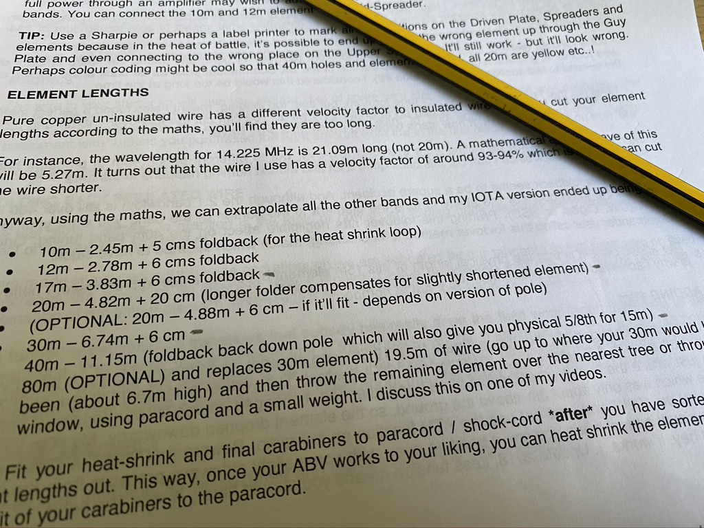
I then referred back to the relevant part of the documentation to get the lengths I needed, then set about measuring and cutting.
I really took quiet a bit of time with measuring, cutting and although not in the instructions, ensuring continiuity between the connector and the end of the wire – reason for this is that whilst I’ve got better at component soldering, my ‘mechanical’ soldering (i.e. joining things for ‘strength’) still leaves alot to be desired. Even with crimping I wanted to make sure I had a working full length of wire before getting it outside and finding out it waswrong
Next step was to label up the discs. I’ve not used my labelling machine in a while, so the first thign to do was to make sure it worked and I was happy with the text size. Thankfully it worked and printed beautifully.
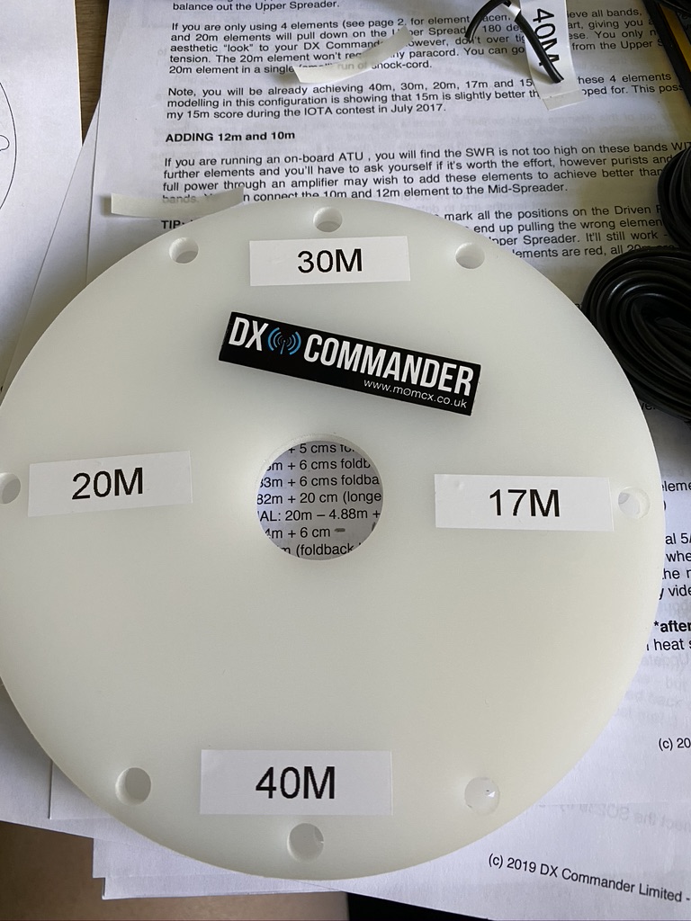
I think i have got the orientation of the wholes correct relative to the SO239, but even if I Havent i can print more lables, but I think I have. Still, its looking good !
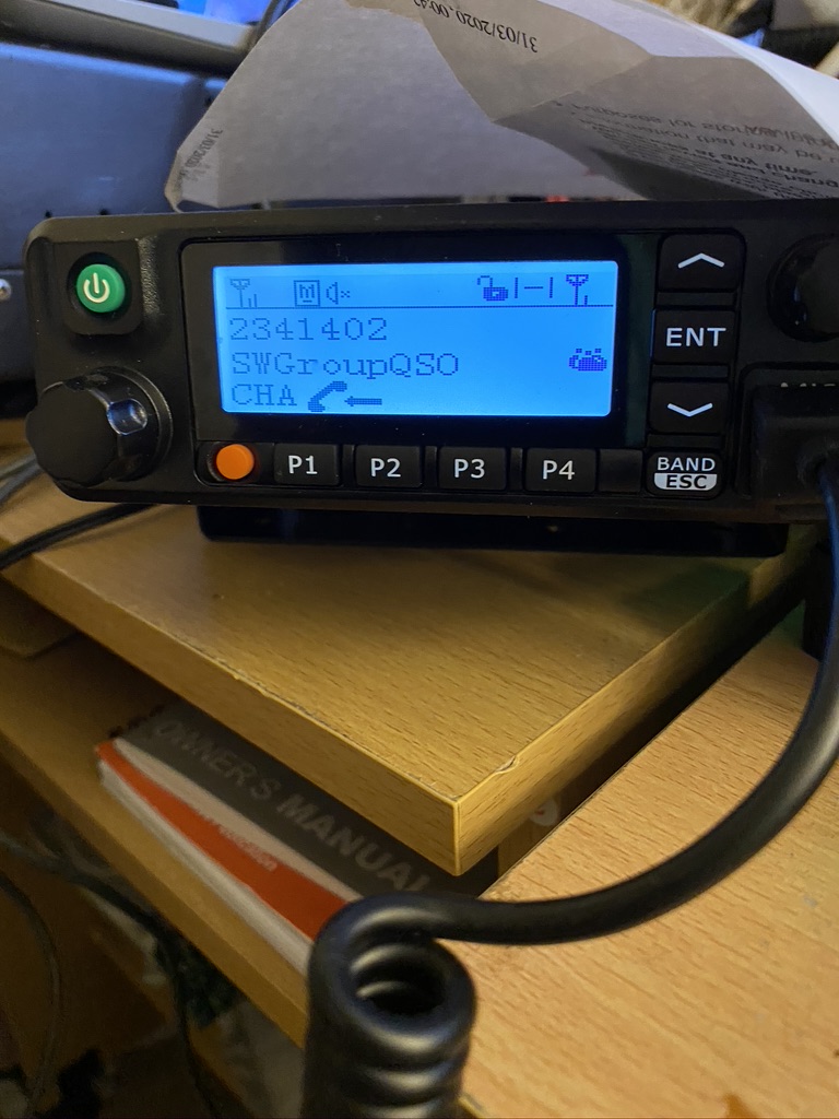
Having completed the verticals and one set from a bunch of four radials it was time for a break and to relax on the radio for a bit. The local repeaters were as busy as ever, so I went back and looked at my DMR Channels – one I had configured, but was wrong due to my newbie status was the local digital repeater (GB7DR) and SW Group talk group. I adjusted that config, pushed it to the transceiver and as luck would have it was able to listen into a very good net for half an hour before having my own QSO with G7FBD who gave me a very warm welcome and told me of the other nets which occur on the talk group.
I’m looking forward to progressing further on the DX Commander tomorrow, I’m not sure I will get it finished, its not good to rush something like this, but will surely add another post.
Have some more kits to finish up on, but thats worthy of its own post soon !
Until then 73’s and take care,
M7ALU / Alan