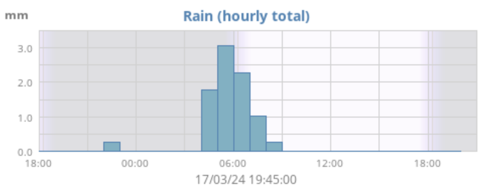
After a very busy week, I had Sunday and getting out with my radio to look forward to. Thankfully the weather was being kind to me, whilst not warm, it wasnt raining as we had plenty of that over night !
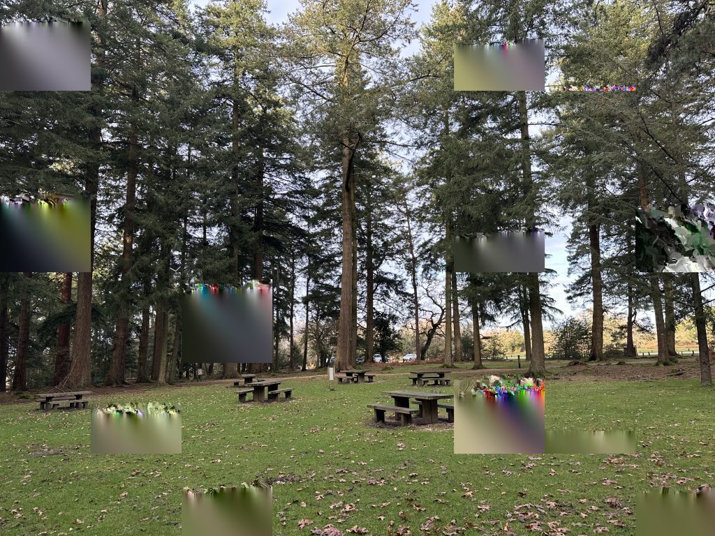
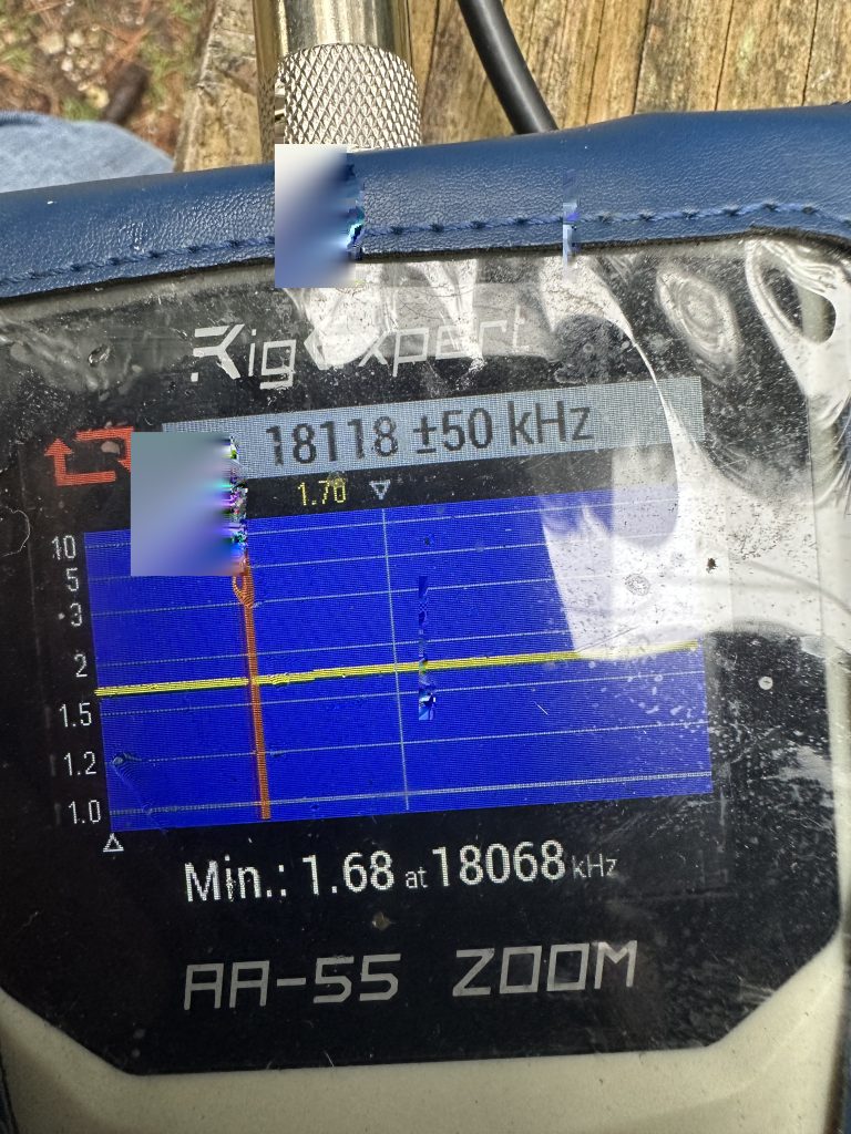
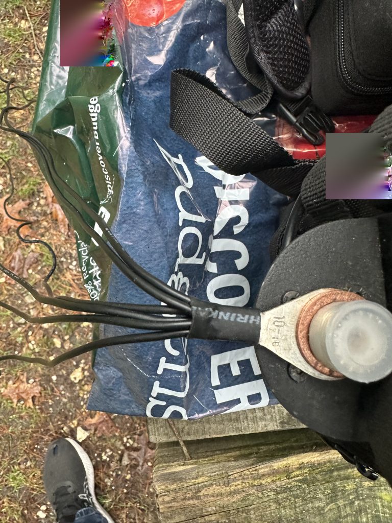
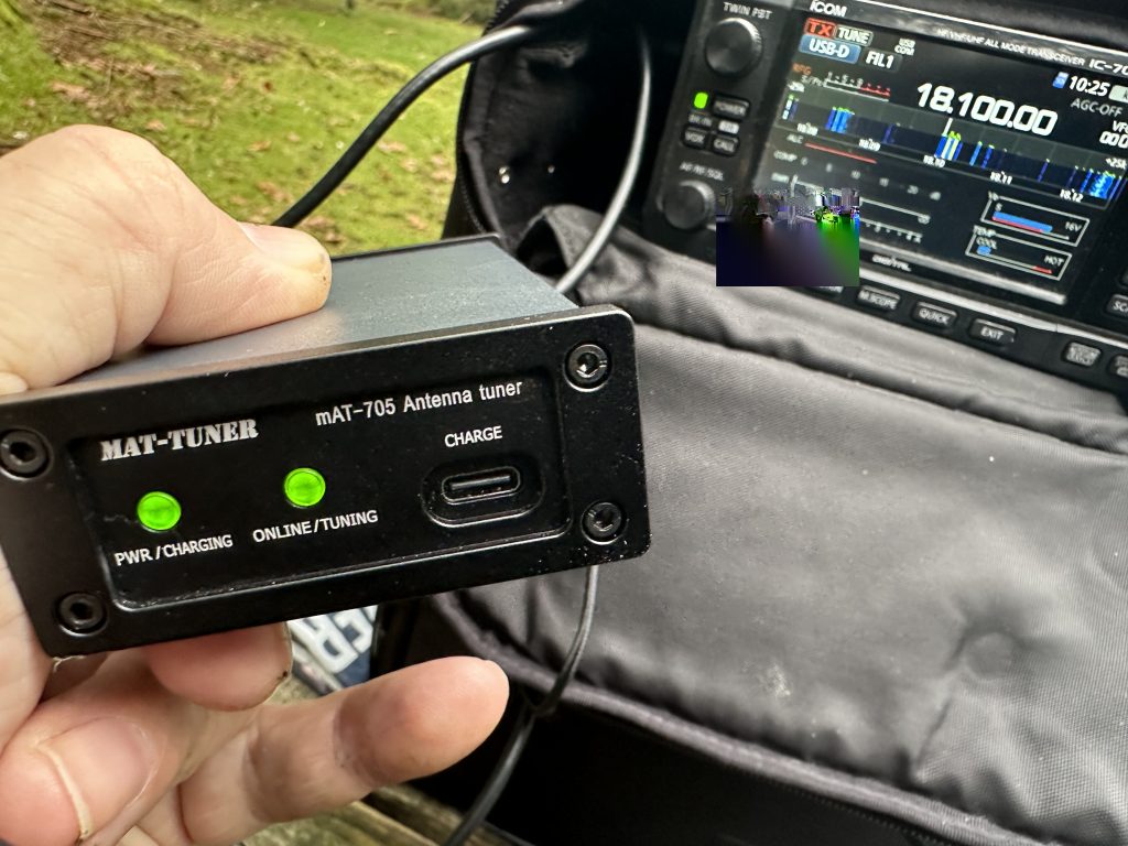
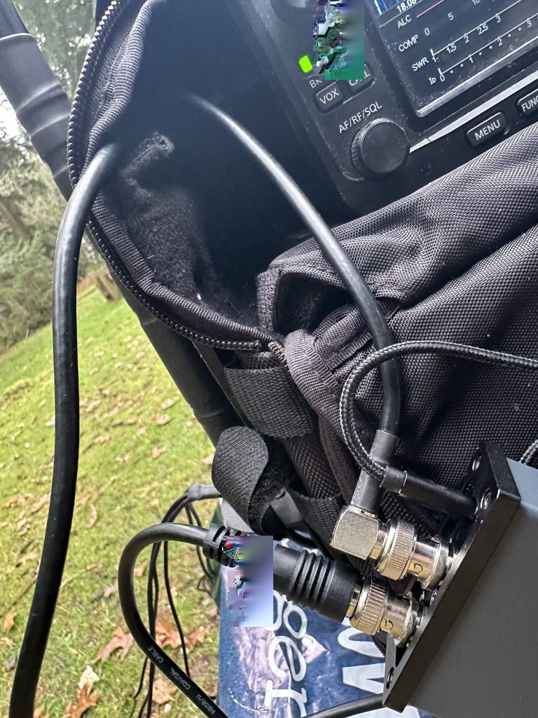
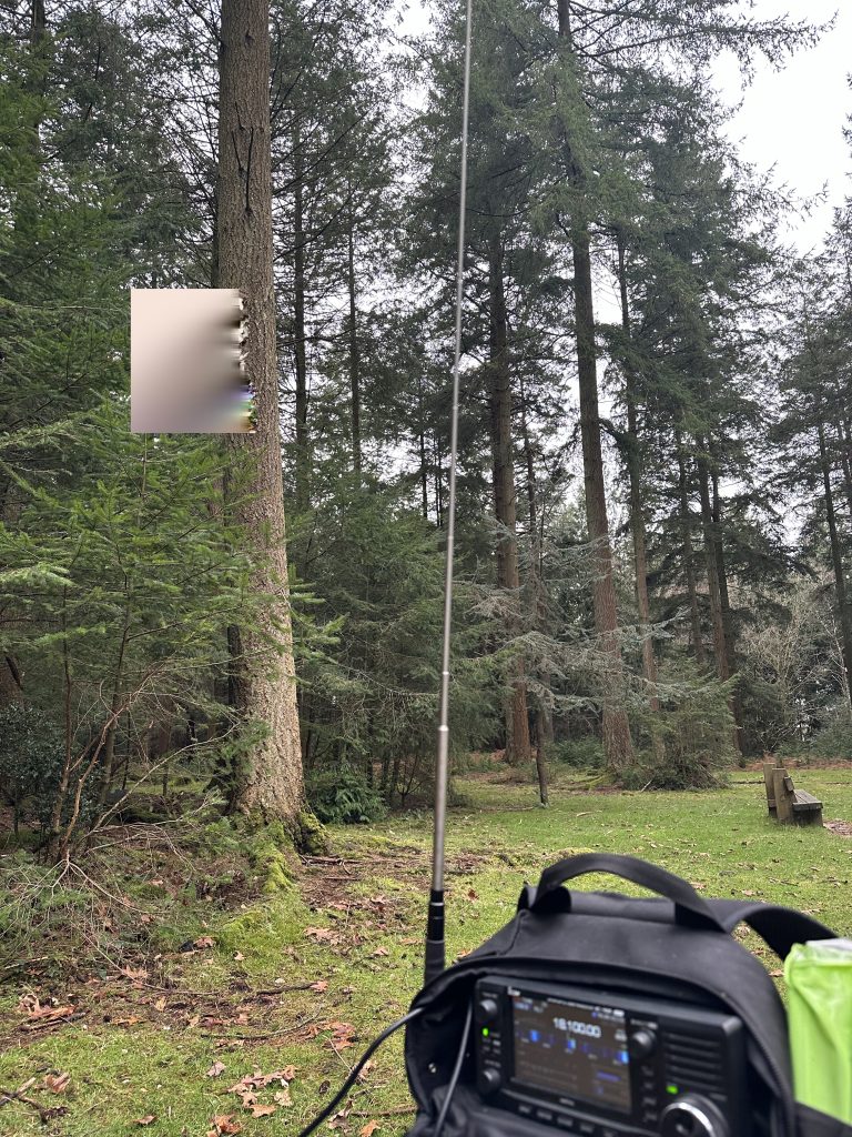
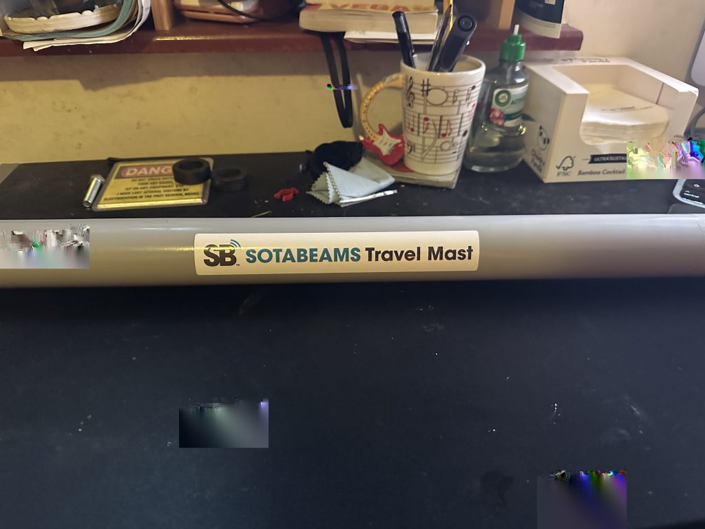
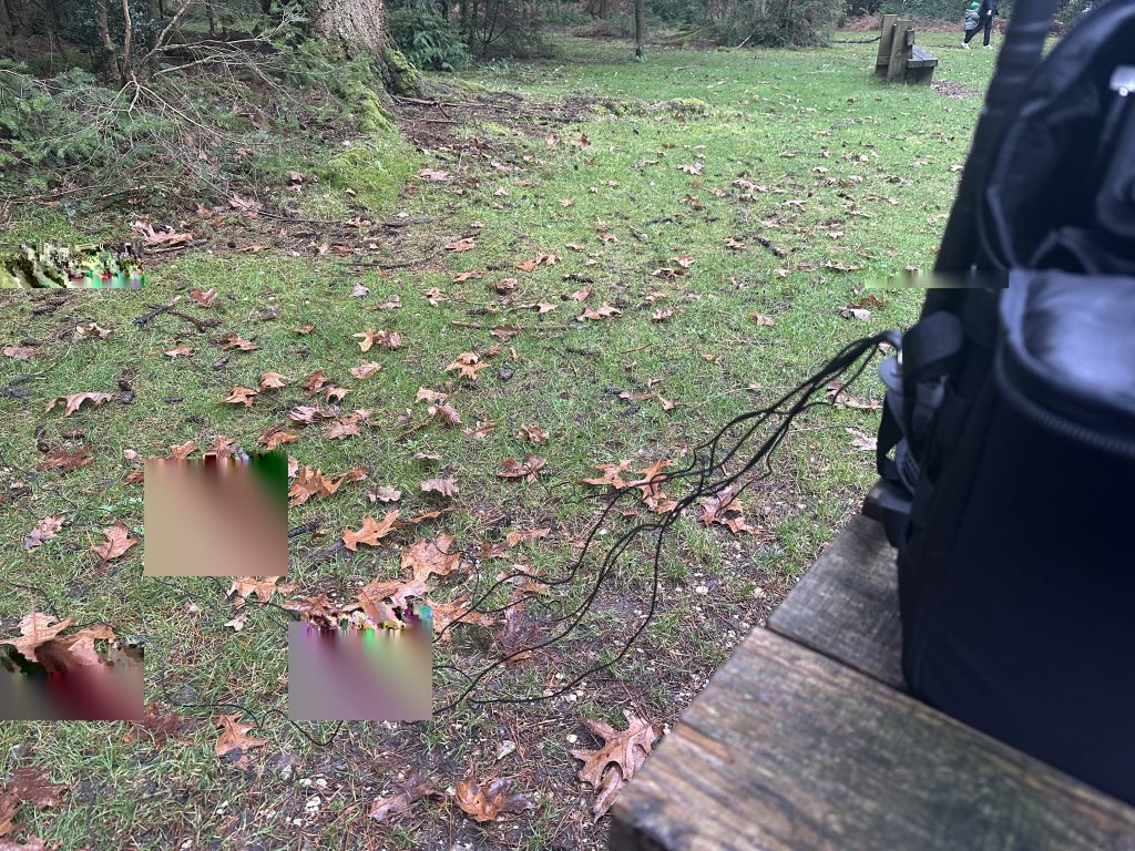
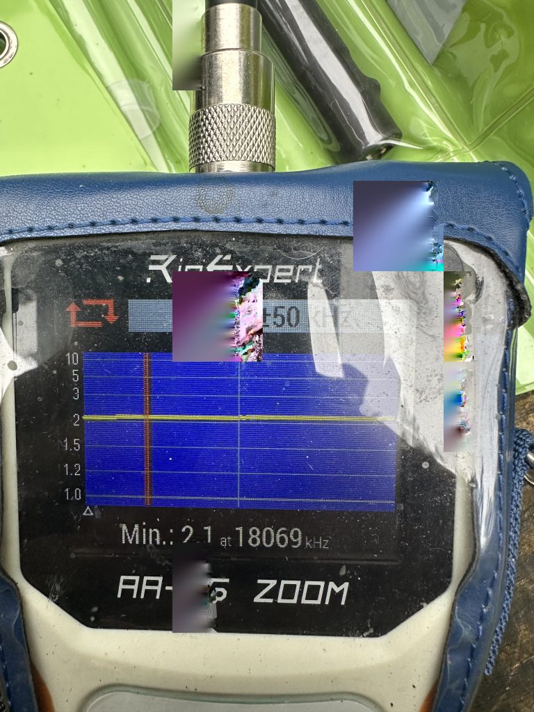
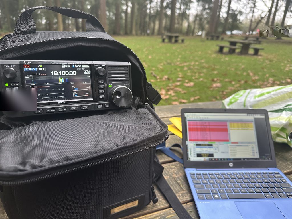
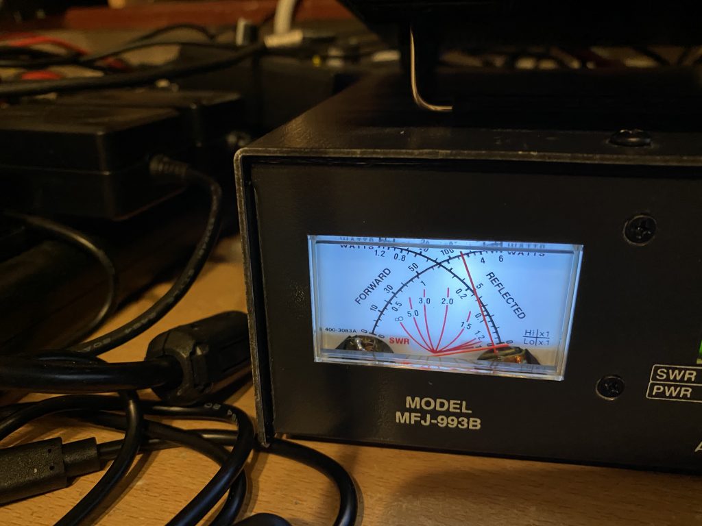
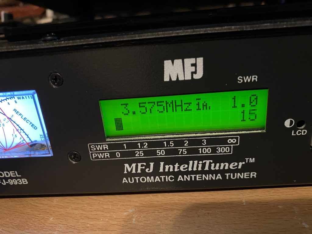
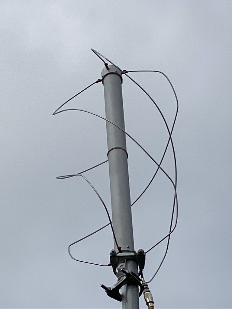
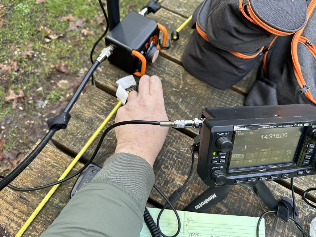
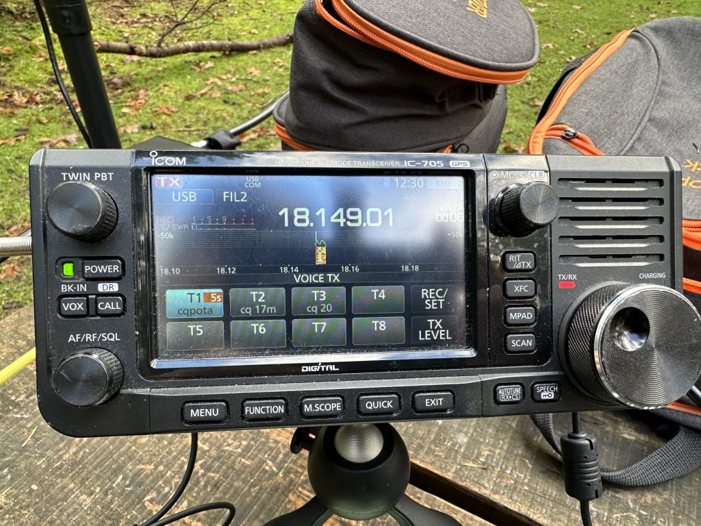
I headed out to Boulderwood with the magloop and 705 and was on the air very quickly. Setup is quick and easy with the magloop and I actually learned a good wait to tune the antenna and get the SWR down quicker.
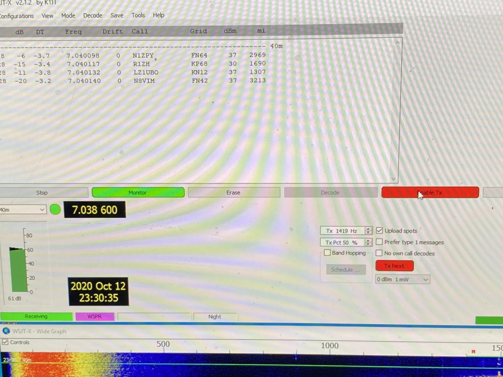
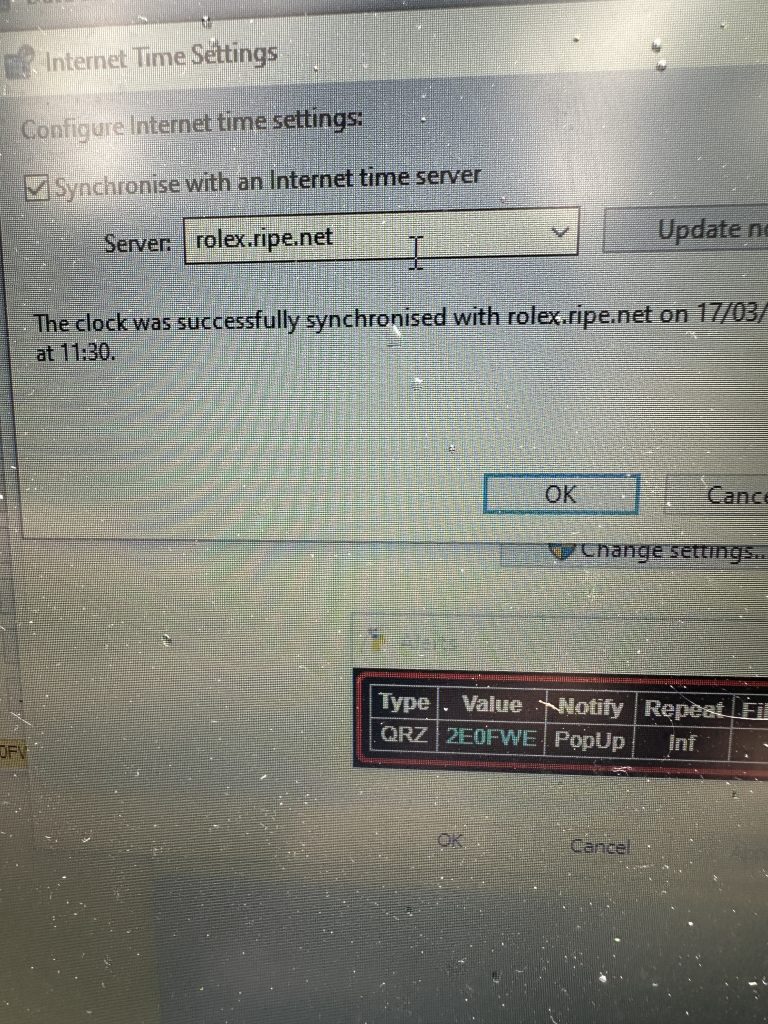
I did run into issues starting out with WSJTX and FT8, the time on my computer was just ever so slightly out, but enough for a time sensitive decode of FT8 not to work correctly. I tried updating the time using the windows time server, to no avail ! I had to manually set the NTP server to rolex.ripe.net, sync the time and I was back in action !
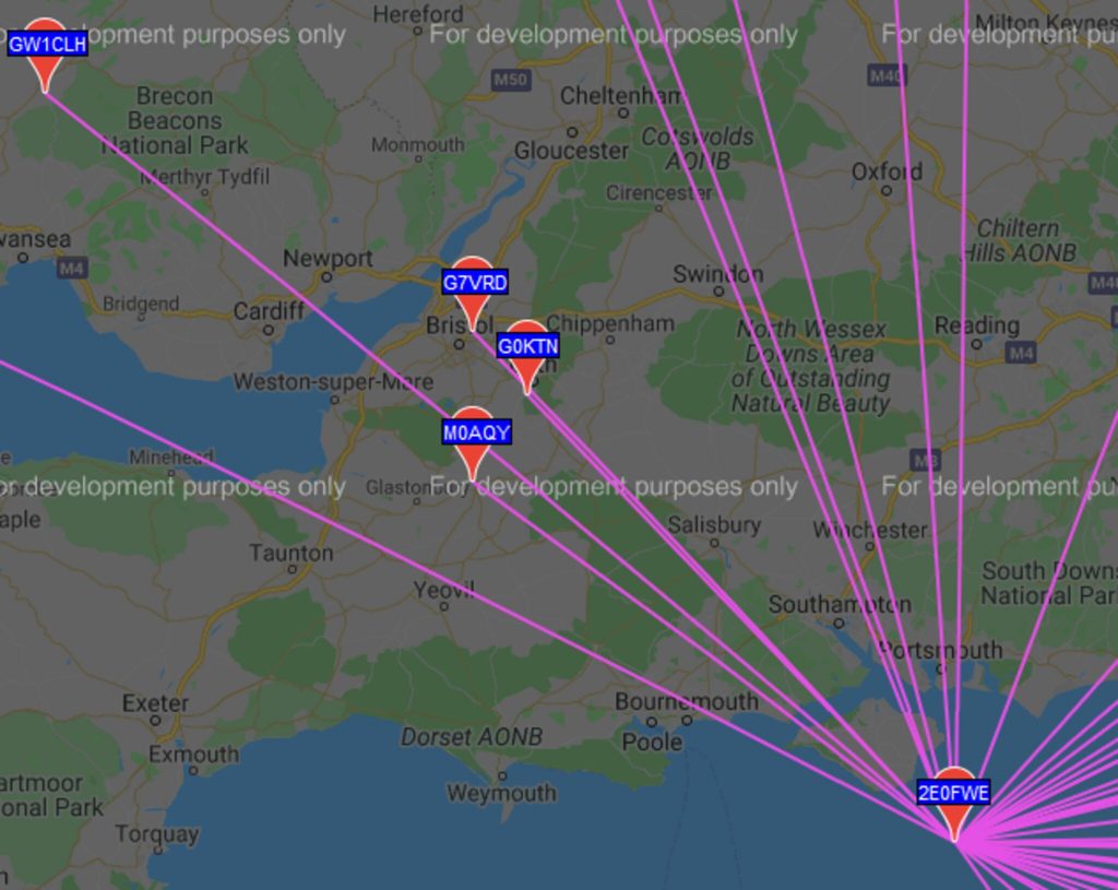
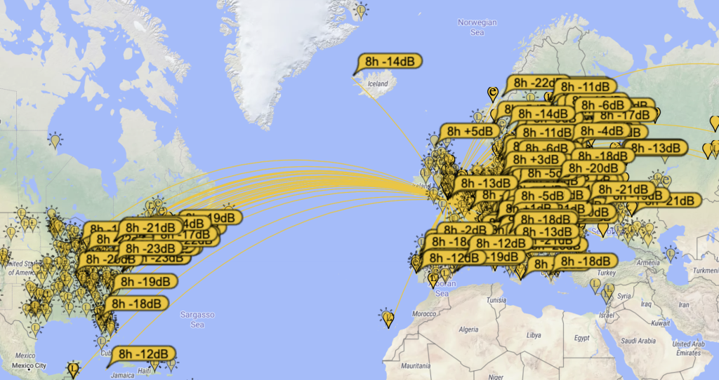
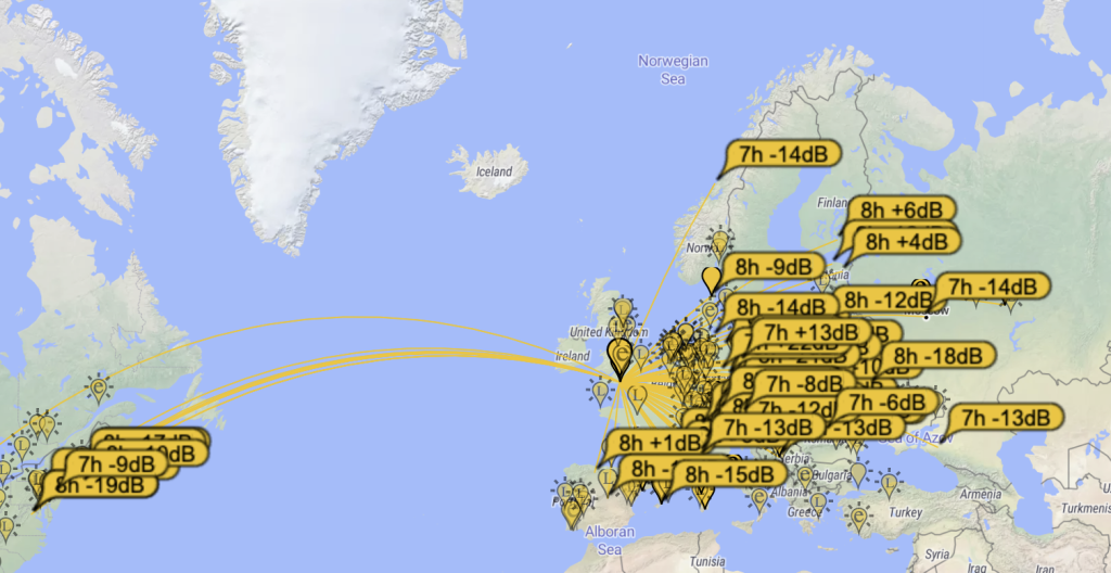
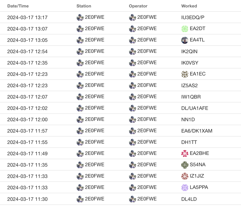
I had 10 QSO’s in digital modes done in under 40 minutes, shifting between FT8 and FT4 on 20m, with POTA hunters chasing me thanks to the POTA app and RBN.
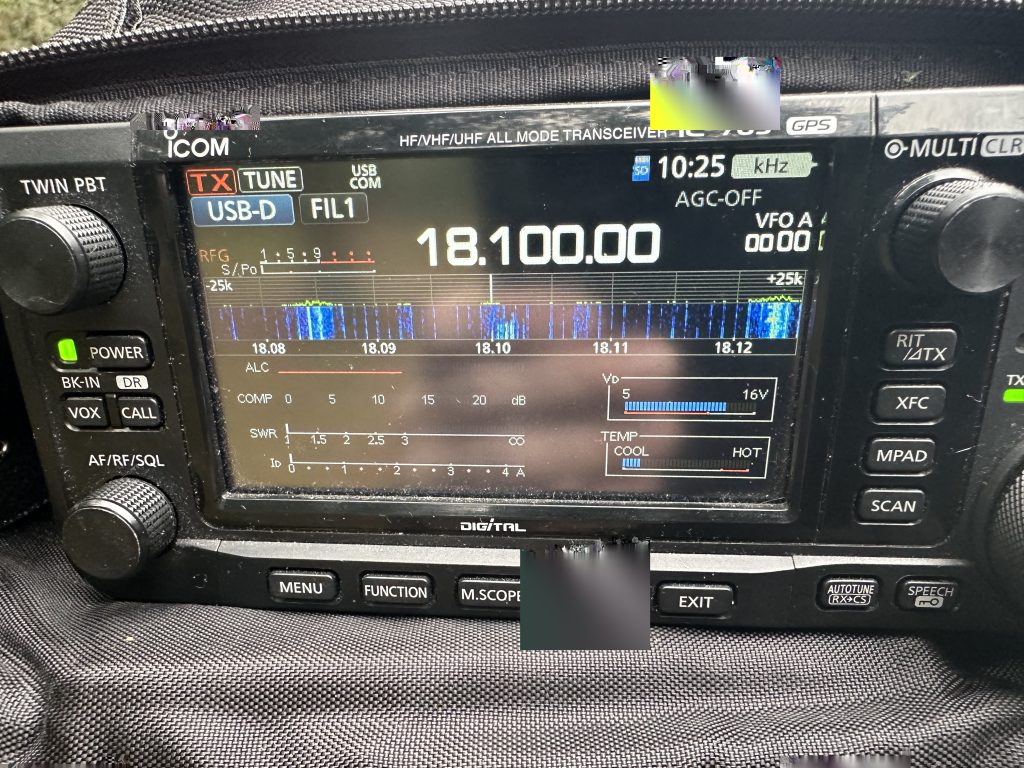
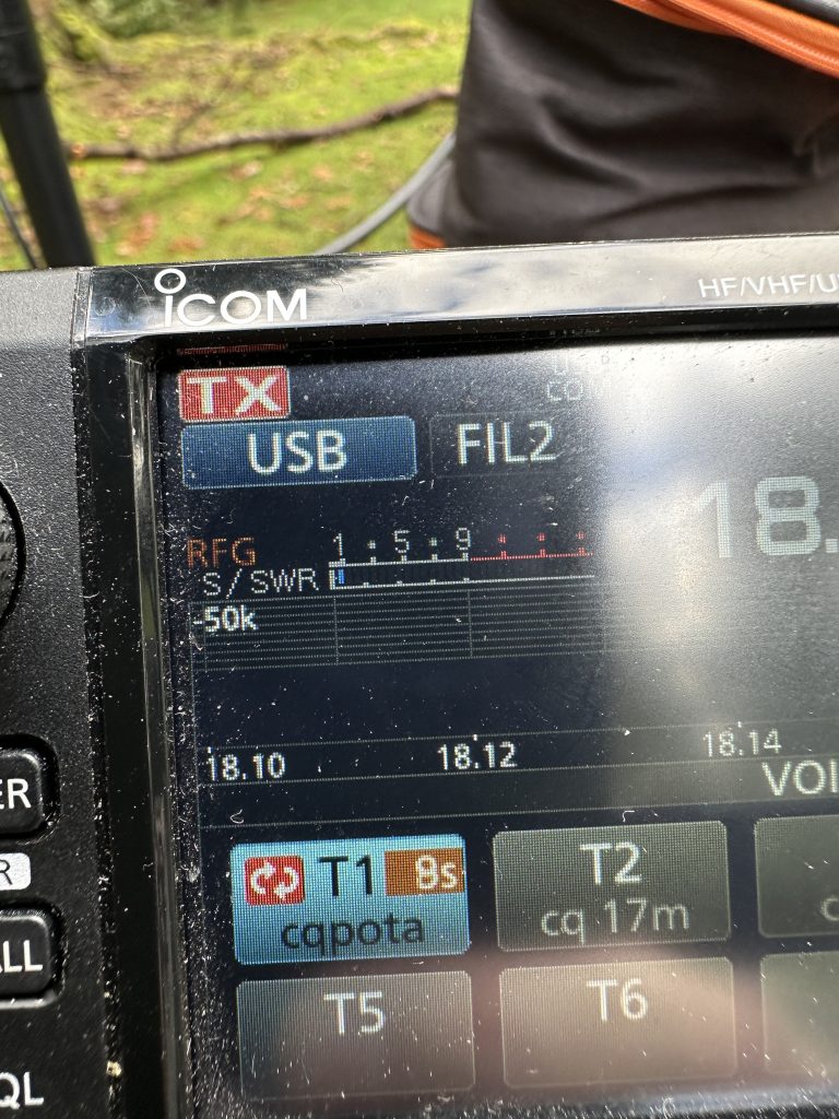
Having completed enough contacts to activate the park, I was straight into Telephony and SSB. I went onto 17m, not that was any contests on, but I found it a good band for QRP operation, and sure enough I made two contacts, with EA1EC being a POTA Hunter, proving how using PoTA makes getting contacts that bit easier – when running QRP it all helps !
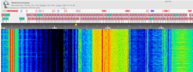
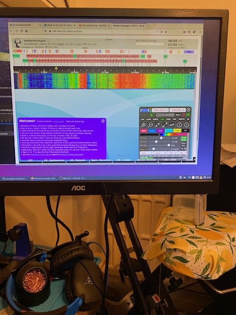
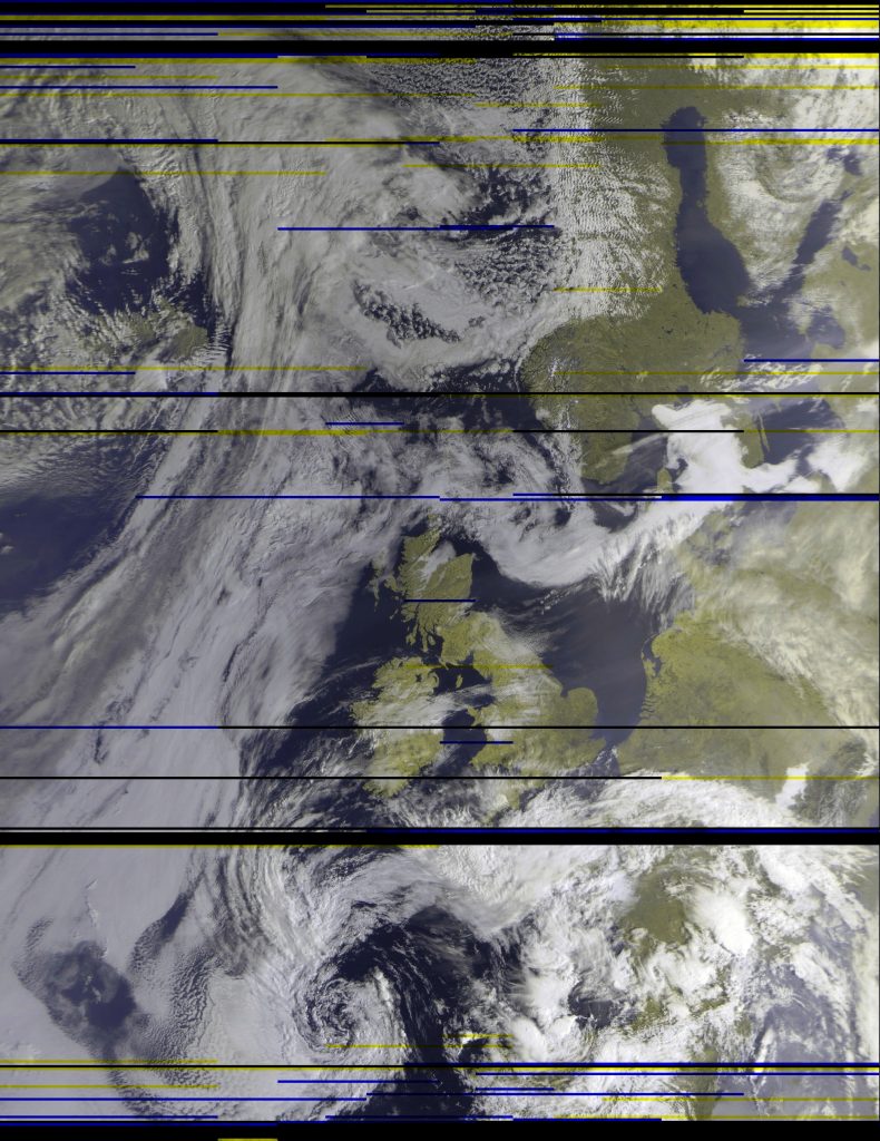
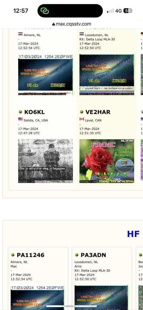
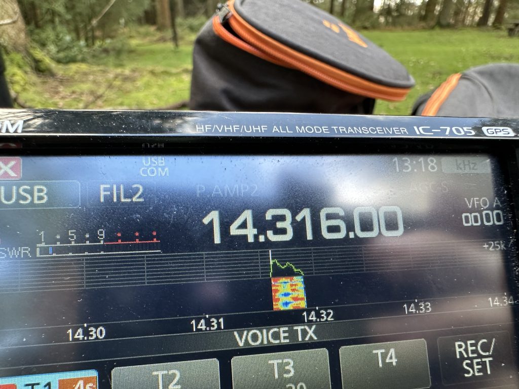
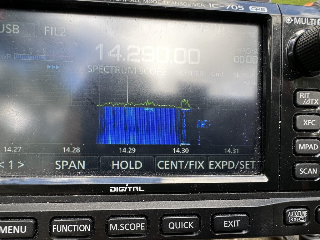
I jumped onto 20M, which was quite calm for a Sunday, and was able to tune around the band, making a contact with IK0VSY, with a good signal report. 20 meters really was the place to be today, so jumped onto SSTV and the pictures started rolling in from other SSTV users.
I waited my time and started to transmit and I made my first SSTV PoTA contact for 2024 ! I was really chuffed and excited, so big thanks to IK2QIN for the excellent QSO.
I then span the dial on 20m once more, and made 3 more SSB contacts, it was really great to make the contacts, with IU3EDQ being Portable !, but thanks again to EA2DT and EA4TL for hunting me and making the contact with excellent signal reports, with a 59 from me and a 5-5 for my reception report.
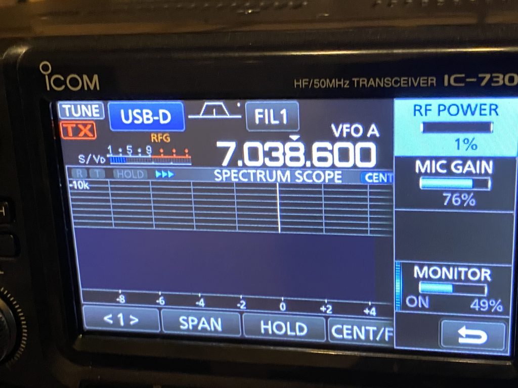
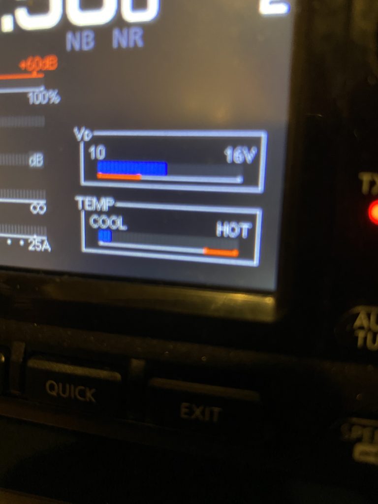
The IC-705 really done me a great service today, and being able to use the the voice repeat mode in conjunction with the ‘massive’ battery power of the ‘ultra max’ battery ensured I wasnt going to run out of power for the radio.
Sadly some massive QRM came in on frequency, but I was able to shift up and continue making contacts, that is the advantage of 20m over 17m, that it has more space in the band, so shifting isnt a problem. I quickly posted my frequency change on the POTA app and was able to continue making contacts !
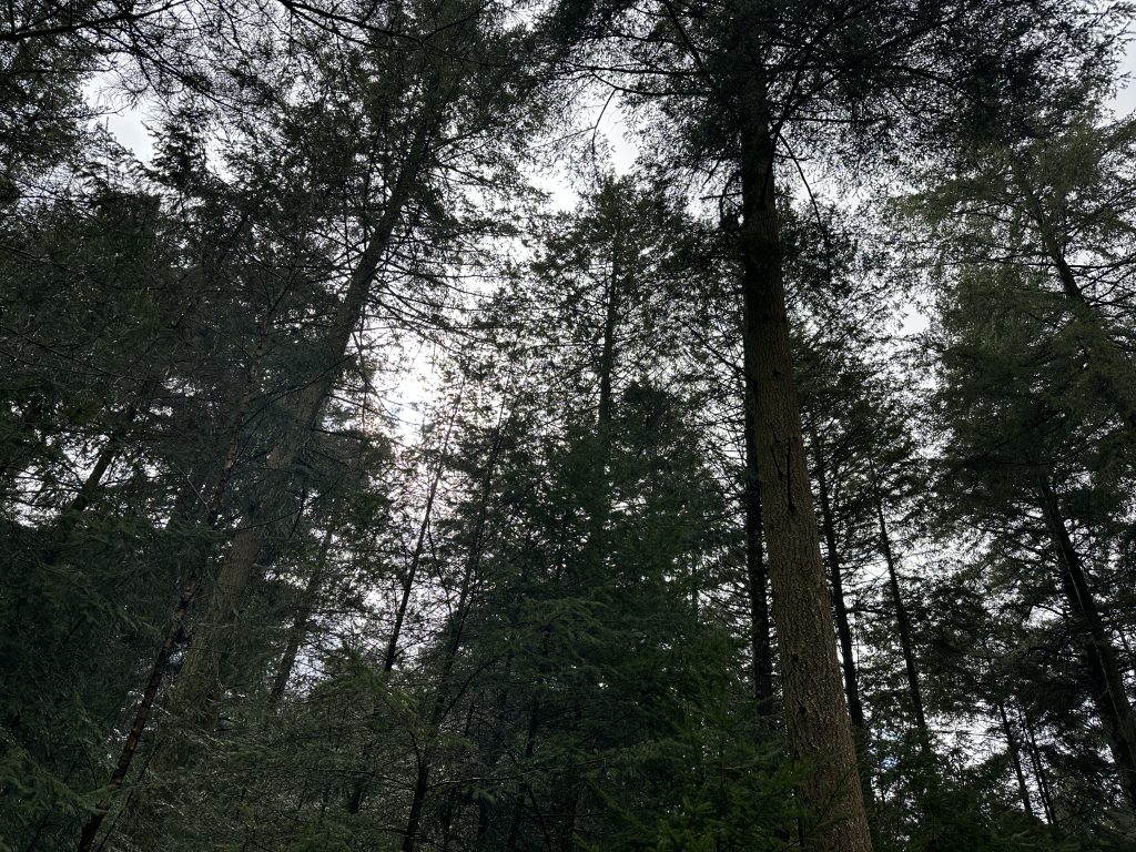
As the time approached for me to head to the supermarket to get my essential shopping, i packed up in no time, leaving the bunch and the park as I found it. Bolderwood is such a lovely place to come, its relaxing and gets me ready for the busy week ahead. I had a fantastic time getting out on the radio today.
Big thanks to all the people that made a contact with me today, it really is much appreciated and I really enjoy the amazing hobby that is amateur radio !
*update 18/3/24*
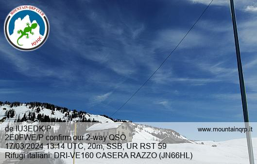
Would like to say BIG thanks to Alessandro who contacted me with his QSL card, little did I know at the time that IU3EDK/P was up a mountain ! I received a lovely QSL card via email and a link to the activation – how amazing that it was a park-to-mountain activation all on 10W of power !!
Thank you Alessandro ! Please check out the activation from Alessandro here