Well its been busy and for the last few weekends very mixed weather here in the UK with masts going up and down due to the winds and more recently forecasts for thunderstorms ! having just passed a mini heat wave here in the uk, it seems the weather, albeit the wind is still blow a bit, has calmed down somewhat !
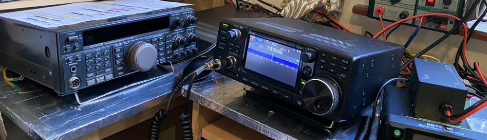
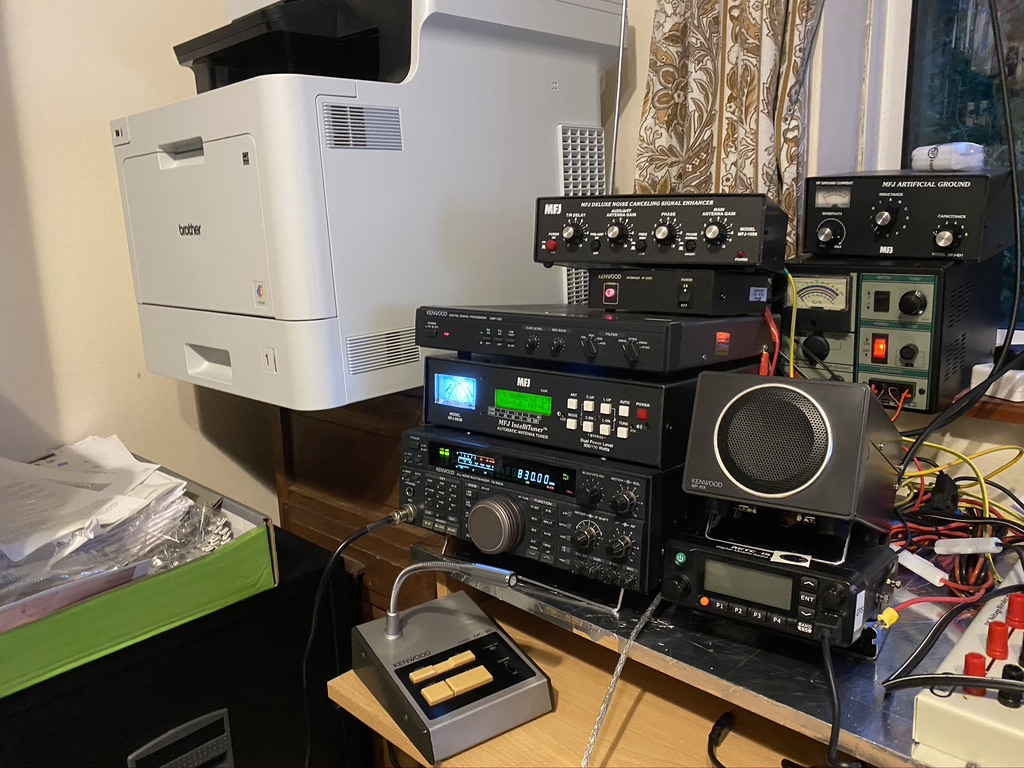
With that I have been tidying up in the shack some more whilst I coudlnt transmit. One thing I was not happy about was the amount of vertical stacking on the TS690s.
The TS690s – keep it ventilated !
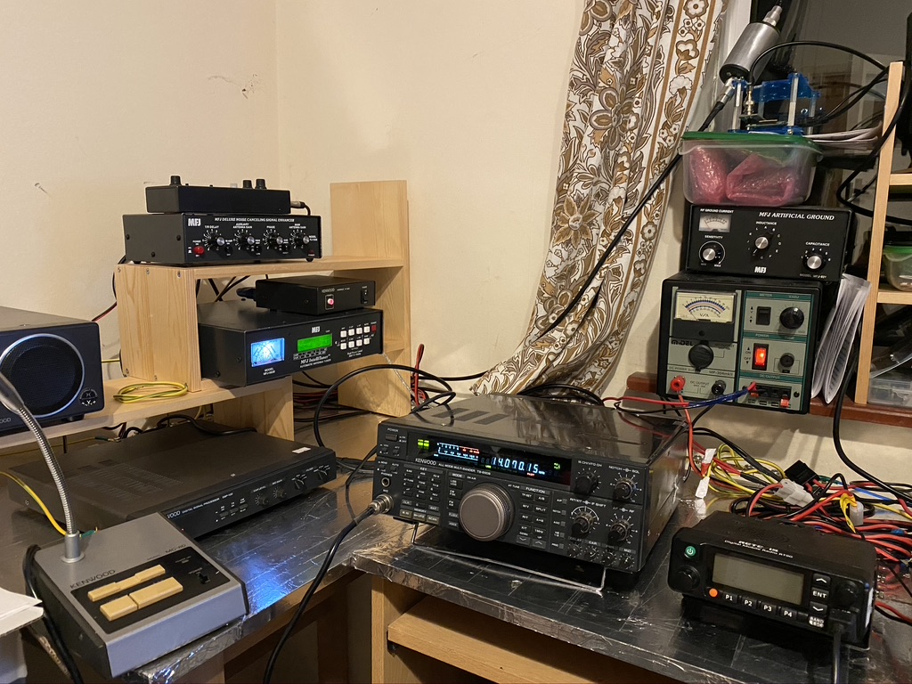
I had a room re-jig and moved all the book-cases to allow an additonal desk to put the associated radio equipment on. This got the same earthing/bonding treatment i had done for the orginal table, which is giving a good common ground amongst the equipment.
A well-breathable TS-690S and DSP100
I’m much happier that with moving the printer and giving room for the equipment it gives a better layout to operate it. I can quite comfortably operate the transceiver from my computer, or if i want to get close and use it direct, have plenty of room.
I have been doing antenna fettling and this weekend and general mast tidying, but thats for another post when i figure out how to show some other developments as well 🙂
So I have been using Wefax for getting fax weather transmissions. I really enjoy them and also find it useful in seeing how much QRM I am getting on the ‘wire’ so to speak. Recently a gentleman on youtube by the name of “Tech Minds” published this excellent video
Build a V-Pole for weather sats
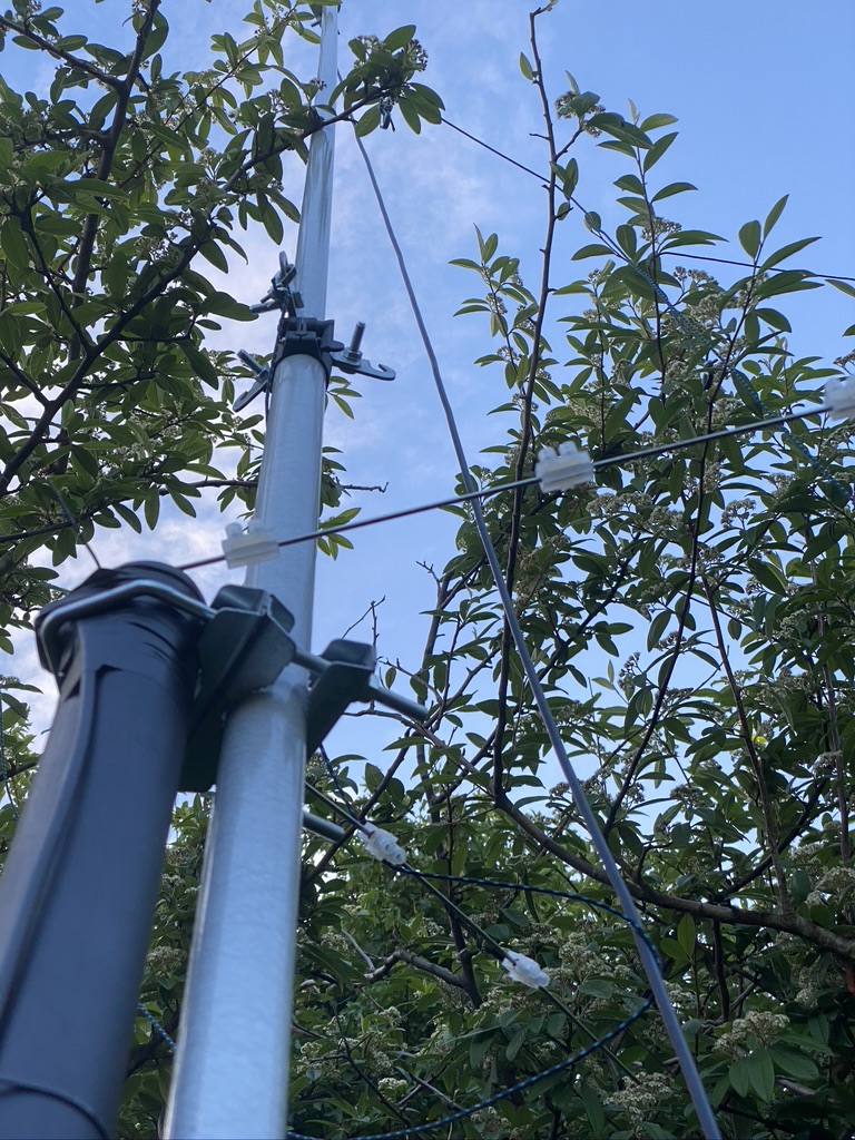
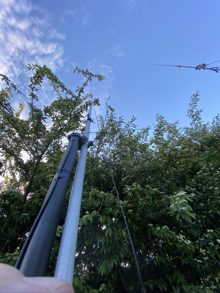
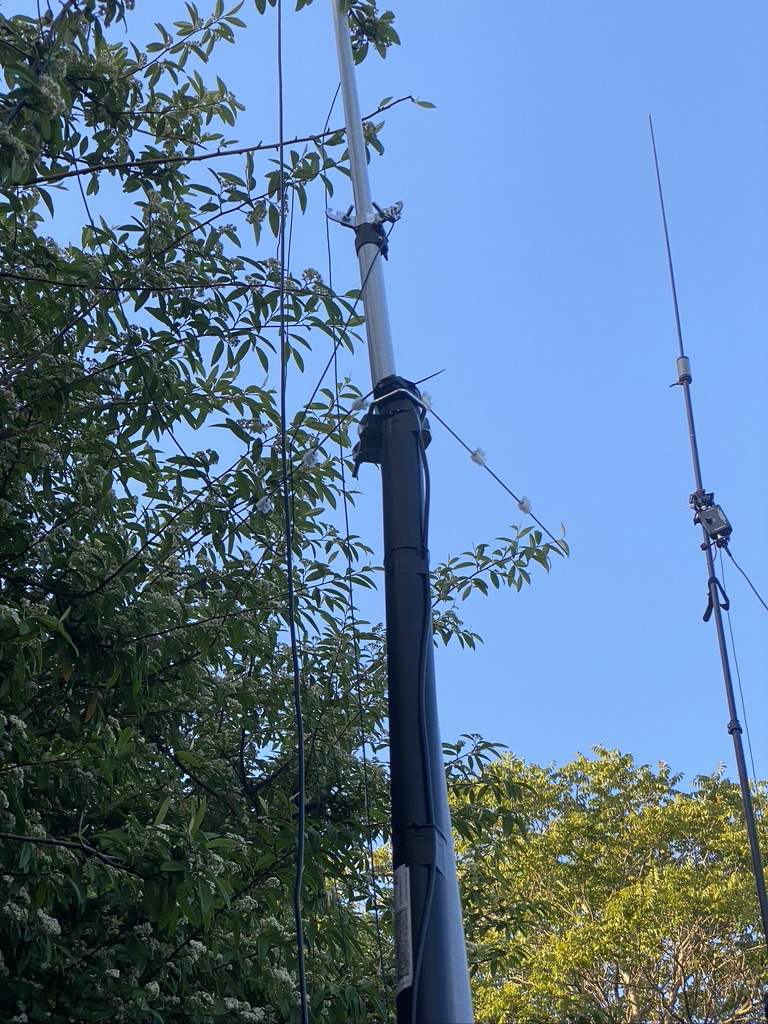
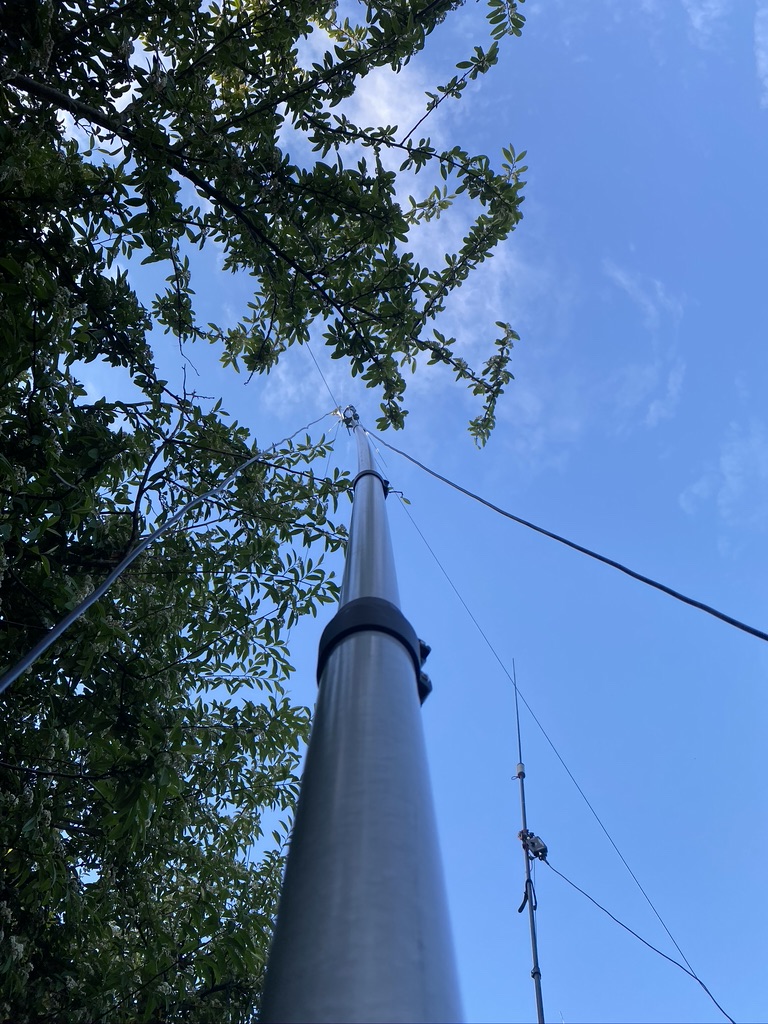
Now I loved the instructions on this video and it has been something I’ve wanted to do. I asked “Tech Minds” if i could put the V-Pole adjacent to a 2m/70cm vertical, to which he said yes, so i was then on a mission to build my V-Dipole.
I already had decent electrical terminator blocks, so didnt need to order those.
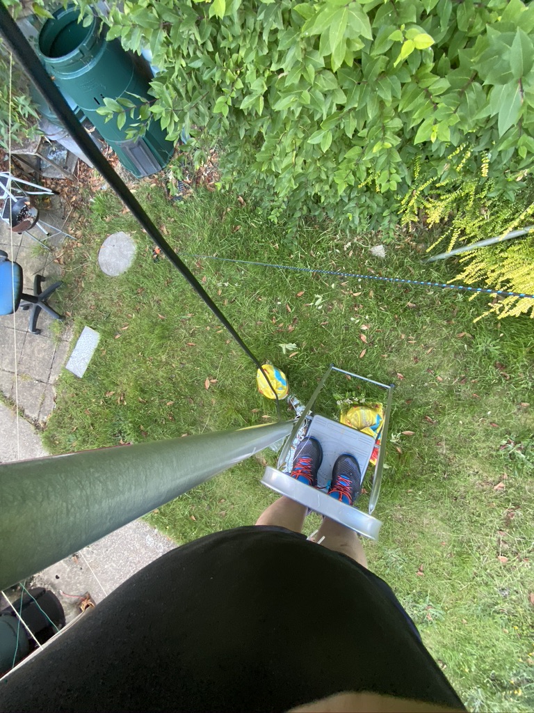
I followed the instructions and set about mounting the antenna on the mast – i have to say i found this quite challenging on my own on how to attach the pvc pole to the mast, but sure enough, and with a few ‘oh dear’ (swearing may of been harsher) on dropping nuts/clamps i got it attached.
I then fed the coax from the mast back into the ‘shack’ where I put a PL-259 socket on .
I do love this video, and the guys no nonese approach
the method i use for puting on a PL259 onto coax.
With that i put the antenna via a PL-259 – SO-239 to SMA cable attached it to the RTL SDR Dongle.
Sure enough, i could pick up radio sounds no problem, so all the effort was worth it !
I then set about installing all the necessary software on my HAM computer, following yet another excellent tutorial from Tech Minds
Setting the software up on Windows
I initally tried with the HackRF, but for some reason it wasnt playing ball. Ironically as I knew that a sat should be overhead, i hooked up my other SDR to a basic scanner antenna, and i could hear the sat overhead ! Immediatly i set about setting up my mac for the receiver.
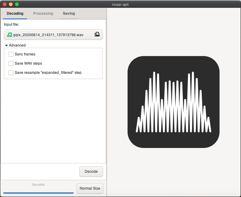
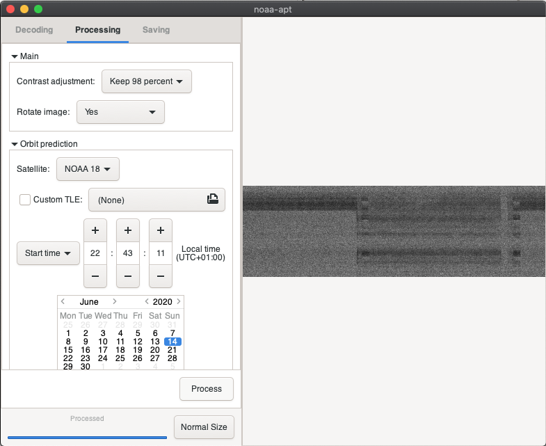
On the mac I used gqrx. The satellite track software is avaiable via macports, but i couldnt find a stable 64 bit version of translation software so used noaa-apt, which whilst not as feature rich, works incredbly well on a mac, as in being actively developed.
I tested with a ‘sample’ NOAA recording, and that produced the required map output ! iwas all set.
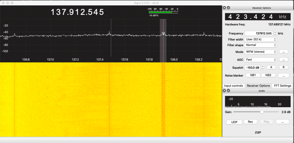
I waited patiently for the sats come and tracking and sure enough within an hour i had my first sat pass over ! Whilst the intial result wasnt amazing, it at least proved that antenna, SDR and decoder worked.
My first NOAA decode !
I then looked for future NOAA passes and a good candiate for going directly over was on for 6pm, so i waited and recorded, sure enough, i got a signal and a decode, and whilst the results arent amazing, its a good start in my book.
Second attempt at 6pm
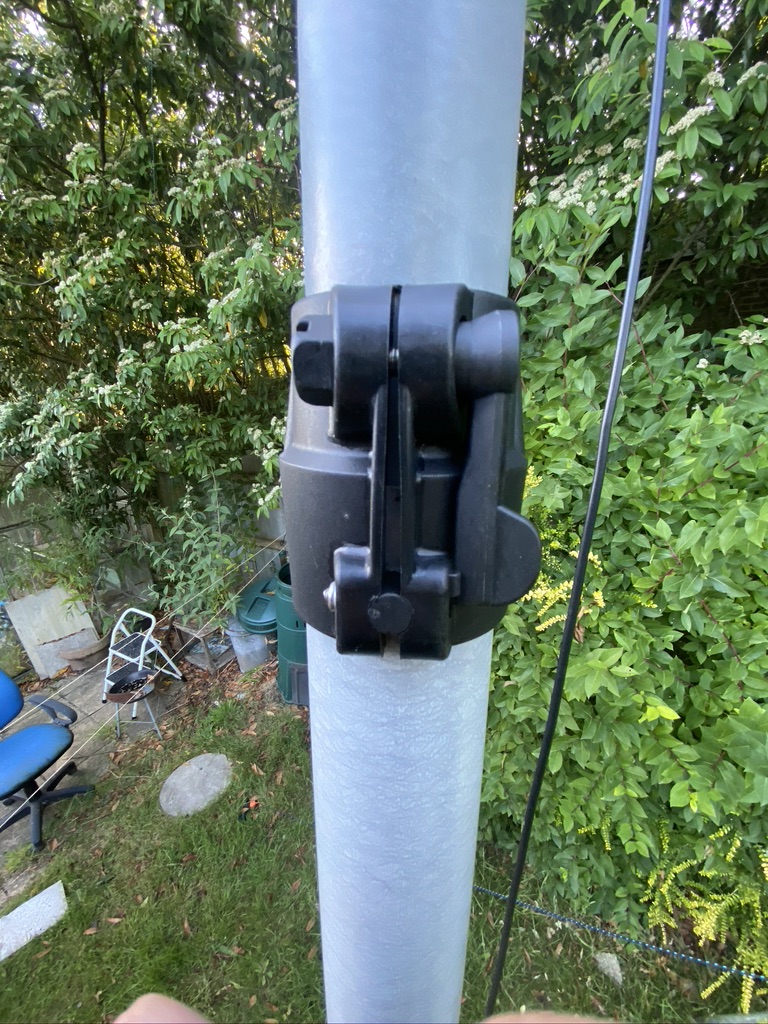
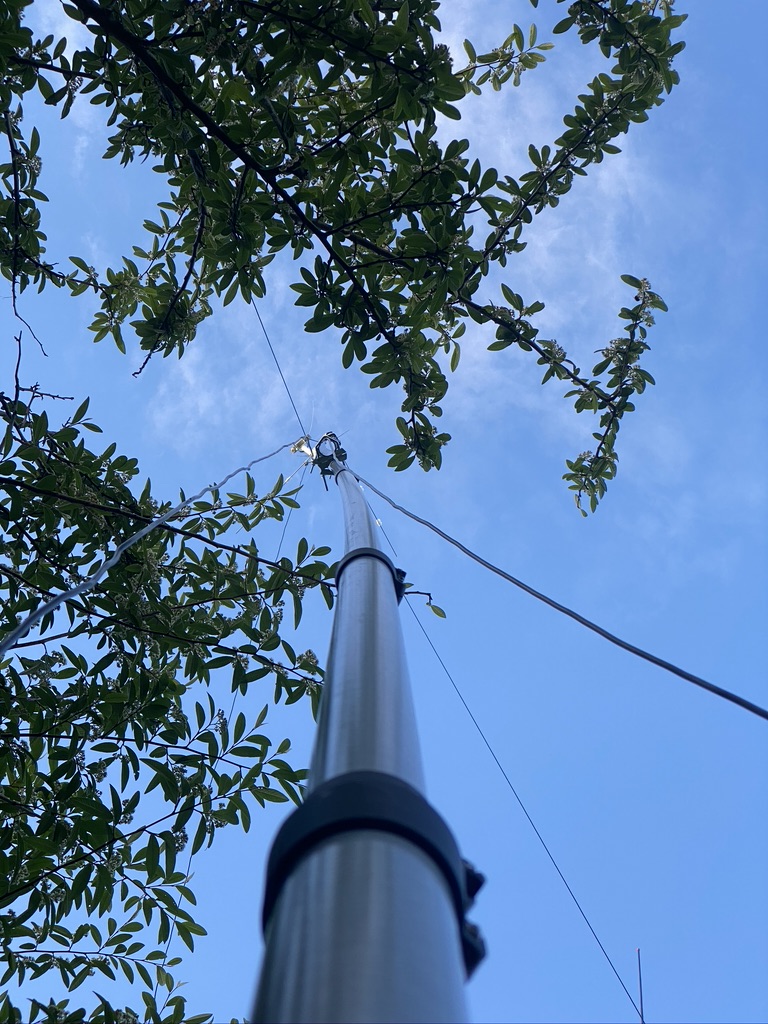
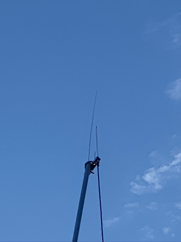
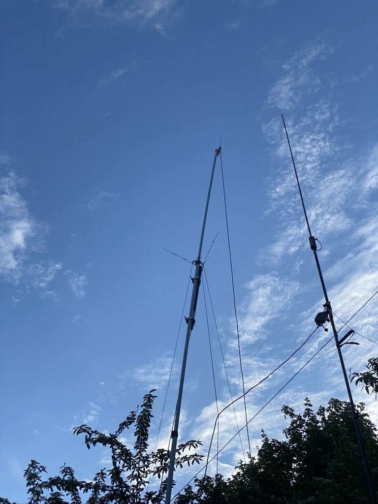
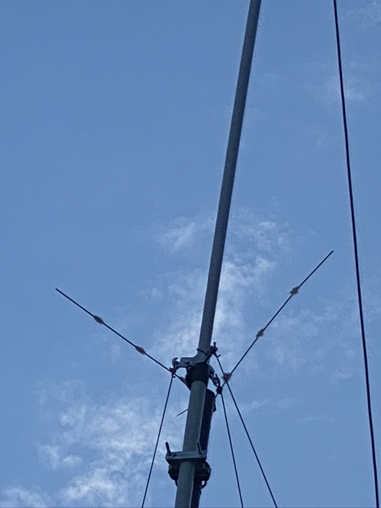
As it was some time before the next pass i set about doing some fettling on the antenna, and found i hadnt got it North-South Aligned that well, so i rotated the antenna and made sure that all the connections were in good form after a full day up in the air.
checking connections
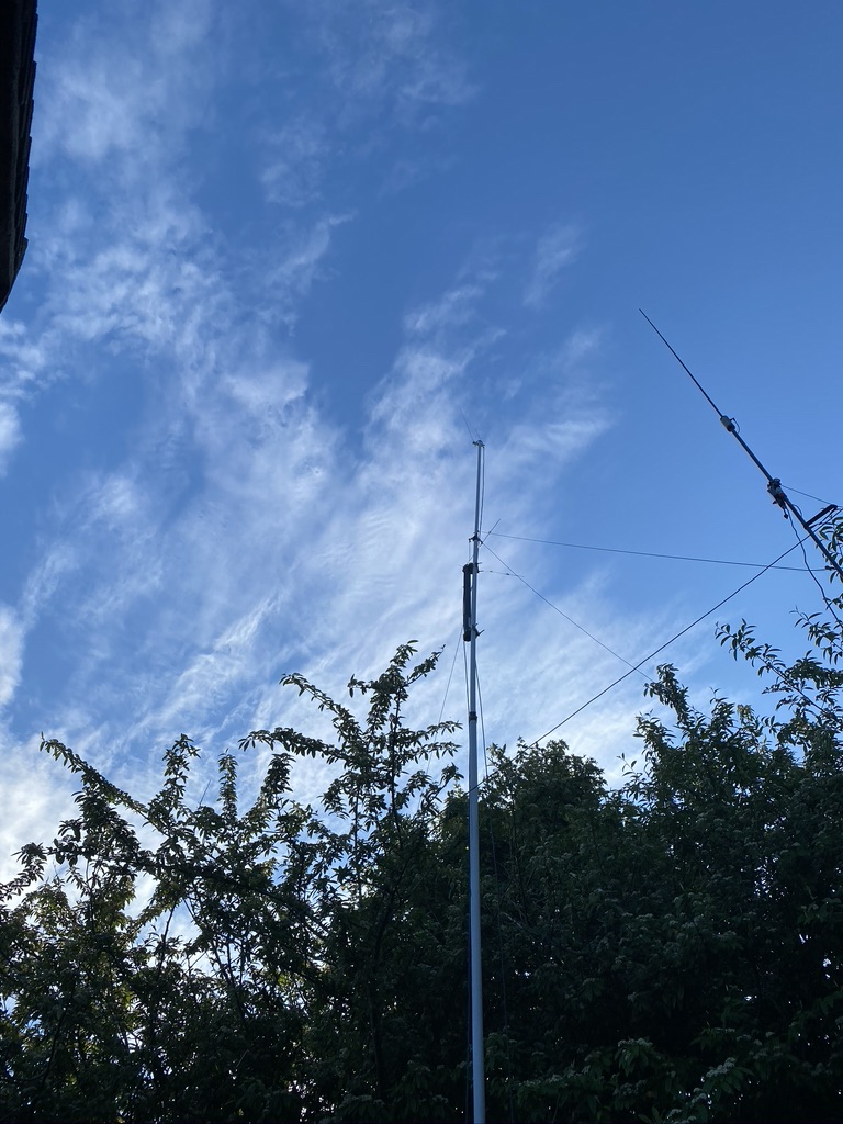
looking good, but those trees !
nicely on the mast, but requires orientation
checking after one day
I’ve not really done a write up of just how good the mast is I use for VHF/UHF, but you can see in the pictures below how high quality it is. All the stages are locking and push up/down without problem, even after rain, they is no fricion on the joints. The locking mechanisim is tough, but gives real confidence the pole isnt going to slip down. I use a ‘light’ guying system as i’ve only got 2 very light weight antennas on the mast (the 2m/70cm and now the NOAA) – any more would be overkill. The guy ropes and ground stakes are incredbly strong and go into the ground some 2ft at a guesstimate, the antenna only ever comes down for the worst weather forecasts.
If you want to invest in a good mast system i can really recommend these
With the antenna back up I now wait for the next good pass to try out how good the scan comes out. Its very exciting (for me) and thanks again to Tech Minds YouTube channel who puts really great content !
I’ll upload my pics to my STOATOPIC account as I get more decodes
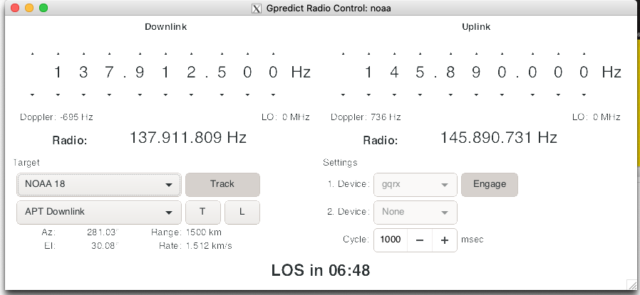
gqrx receiving noaa 18gpredict communcating with gqrxtracking NOAA18 as it flys over my QTH
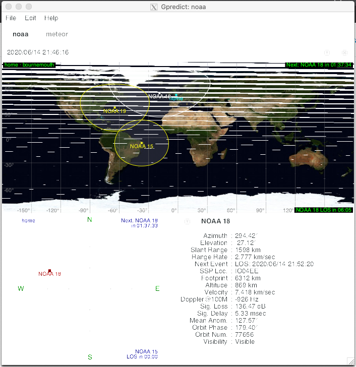
Tracking pattern
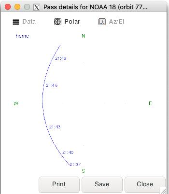
tracking of the pass, i can pick it up from 21:43Decode in NOAA-APTIts another fuzzy one!only the code-strip is visble, but keep trying !
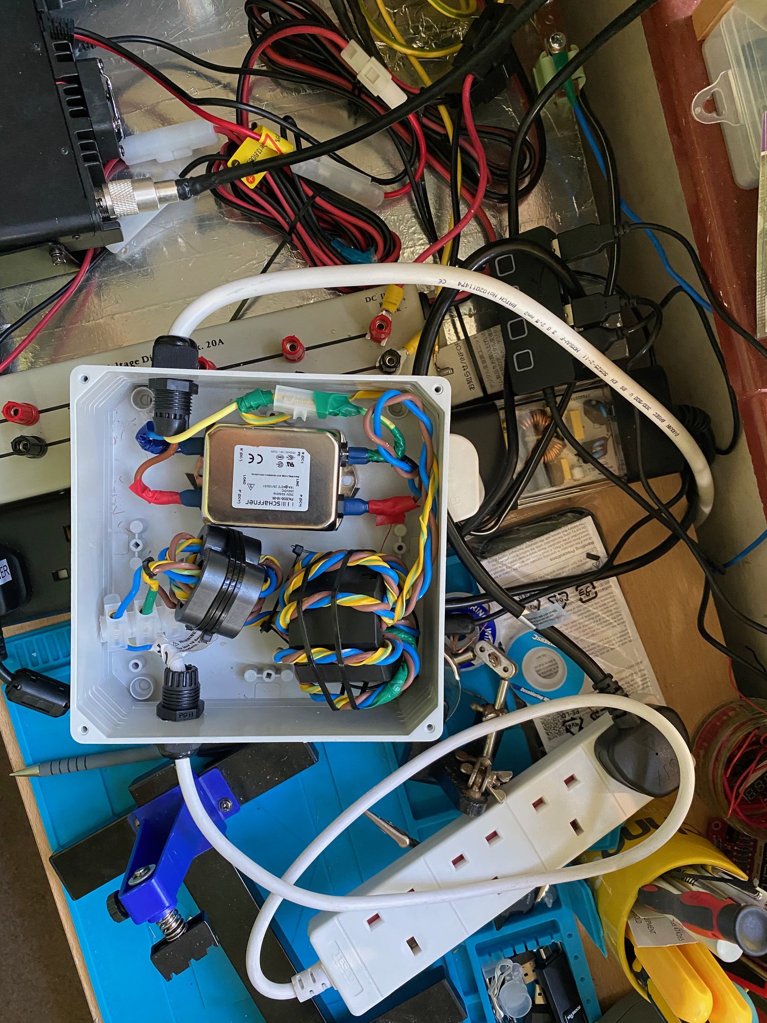
*** PLEASE NOTE PHIL’S OBSERVATION OF MY BUILD (FILTER ORIENTATION) BELOW ***
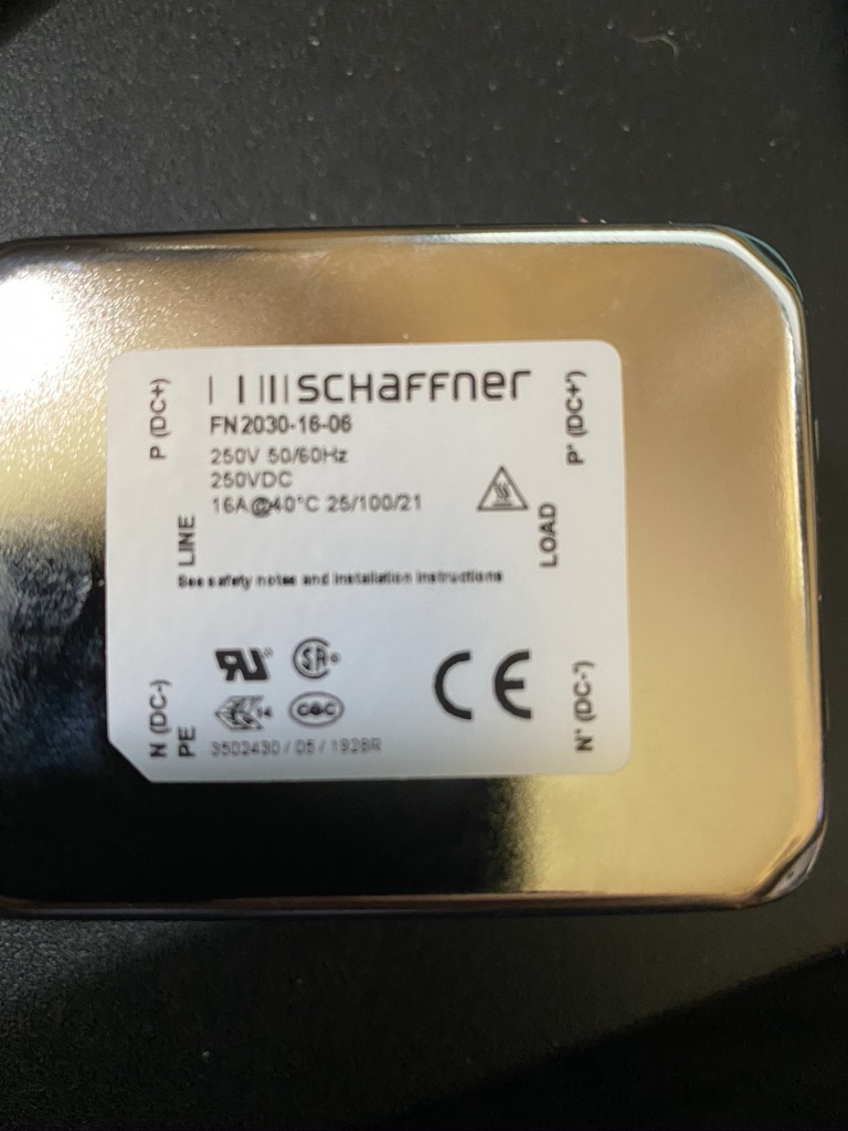
I was using the origninal picture and refrencing off the *EARTH* location post, and not looking at the label (LOAD/LINE) – I have since corrected – afaik no damage done, but good to get right first time if you are using the same filter (FN2030-16-06 FILTER) which has a different layout and orientation to the one used in the slides
*** PLEASE NOTE PHIL’S OBSERVATION OF MY BUILD (FILTER ORIENTATION) BELOW ***
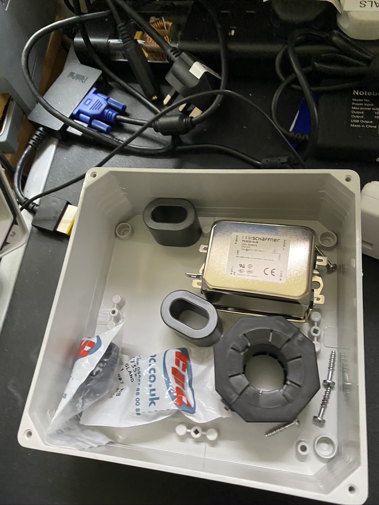
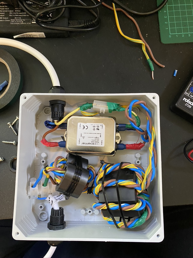
Back in May I built this filter for my shack, which provided suitably good results for the time and effort employed. Further to that post G8KVM (Personal “Bern”) posted a follow up link to an updated filter here.
The main difference to this filter was it contained multiple and updated ferrite types as well as a mains-filter. I was immediatly drawn to the idea of further reducing the QRM into the shack as the first filter provided good results.
I would like to point out that when ordering the mains filter (2030-16-06) the picture on the site is an AC filter. The once I received had DC on it, although the product code was the same.
supplied parts
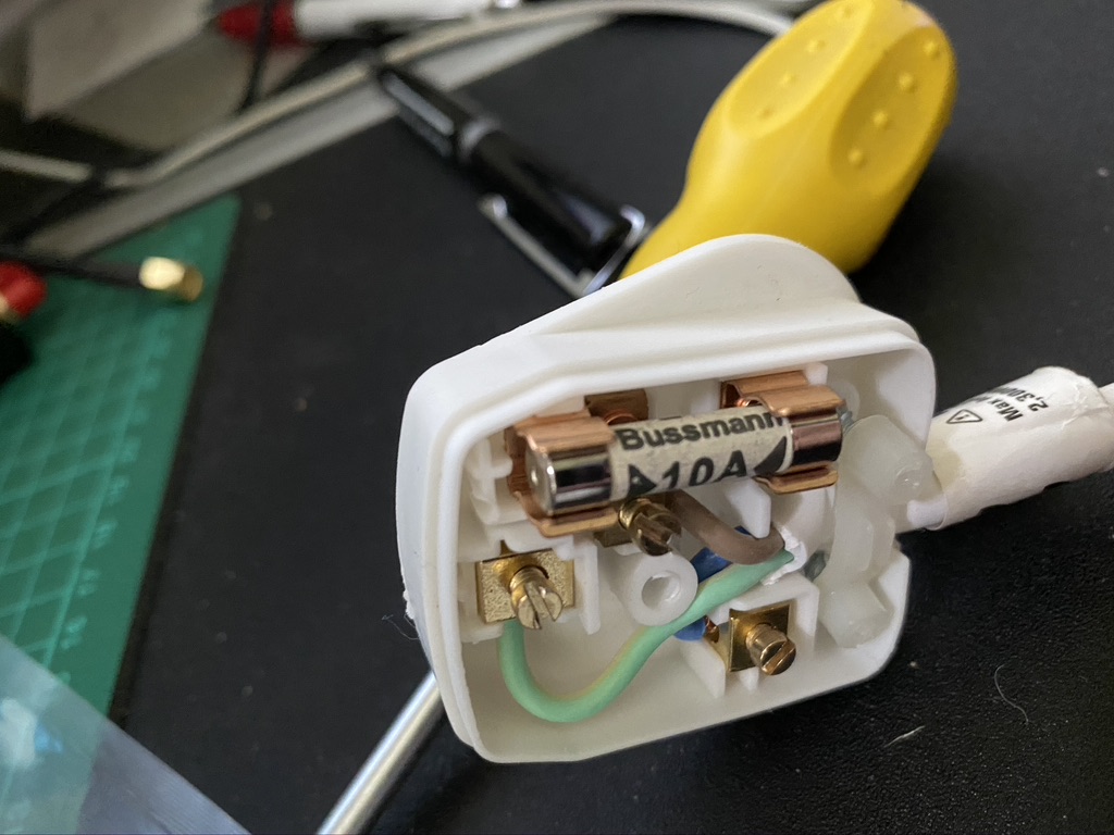
using an existing 10Amp plug
DC Description on the filter sticker
Components, 10A plug and DC Filter, although same 2030-16-06 name
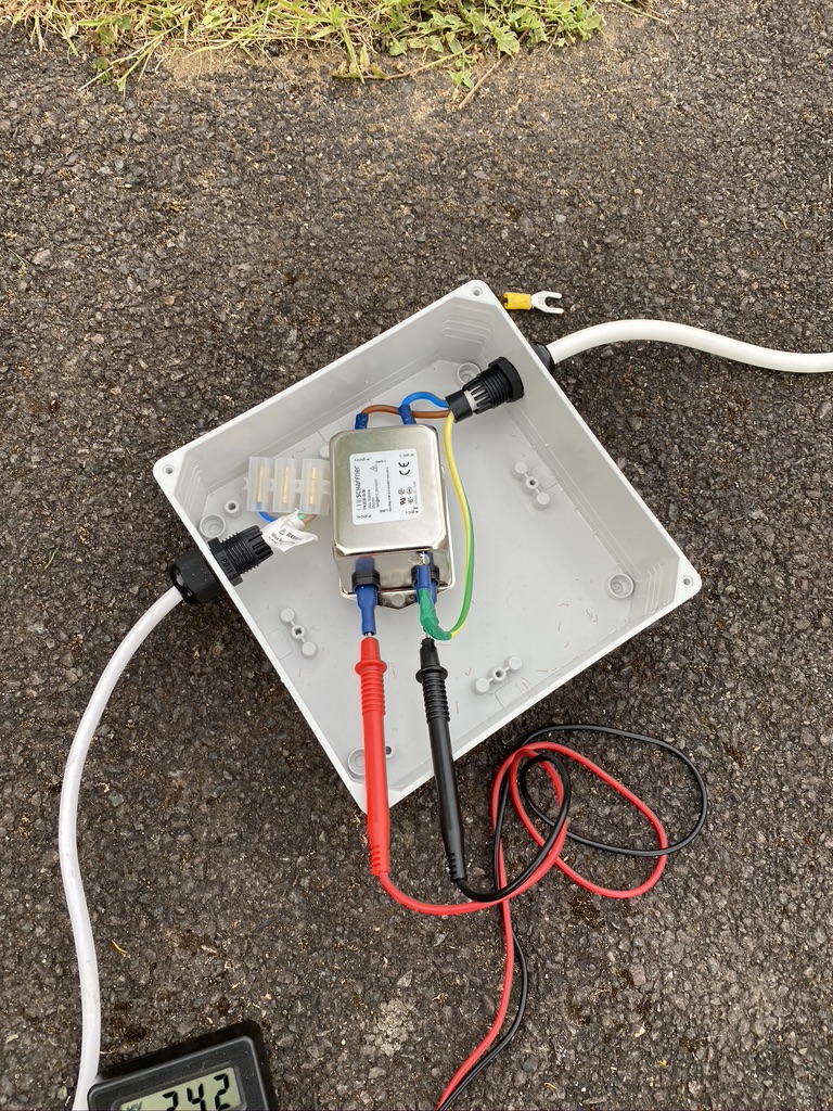
I was slightly worried about the filter saying DC on it, where this is receiving AC current from the mains supply. Whilst rated for 250V i was not going to take any risks, so setup a test-bed outside, where it was thankfully dry and sunny.
apply voltmeter (AC)
turn power on, read meter
verify earth lead correctly attached to case
voltage testing
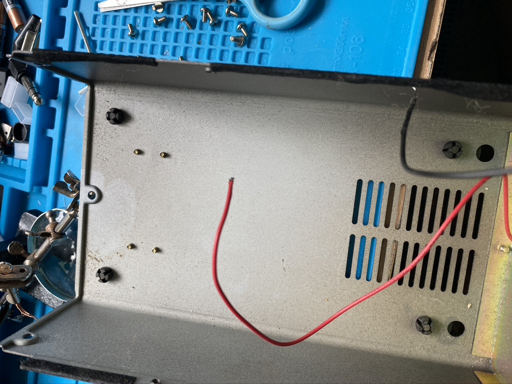
I set about by first running an unplugged in extenstion, plugging the filter into that, and setting up my voltmeter to read AC from the output terminals. There is only one earth on the casing.
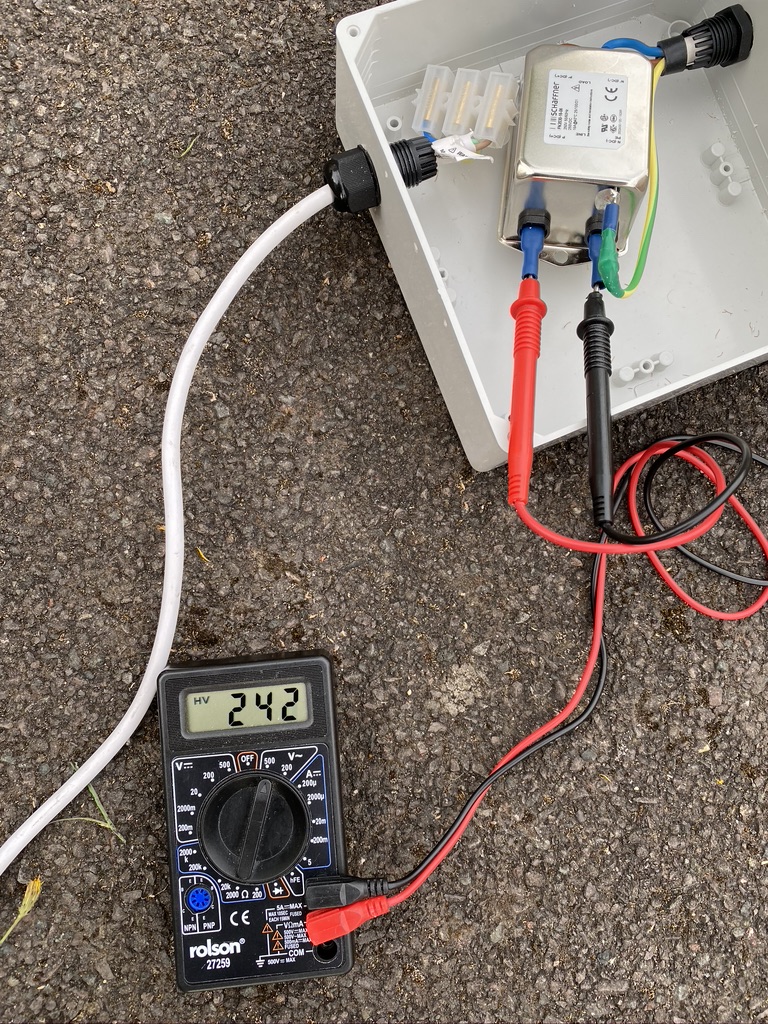
I then went back in doors turned on the power and no popping/arcing/fusetripping was observed. I then checked the output on the voltmeter, and sure enough it was good 240V AC coming out the filter.
I then proceeded to complete the winding for the ferrites.
The cable i used was SEL 10 m 2.5 mm Twin and Earth Cable. This very good solid copper wire. I did have to put on some Electrical PVC Yellow/Green Earth Sleeving to the earth-copper as this is bare when it comes out the original sleeve. I didn’t want to use my electric drill for the twisting of the wire, so done this by hand. Whilst physically demanding, i felt it provided safer and better results.
I was then able to twist the cable thru the torids as per directions. I was rather happy with the results, as it was quite tough to get the cable thru the torid and space it nicely.
filter and torids fitted into the box
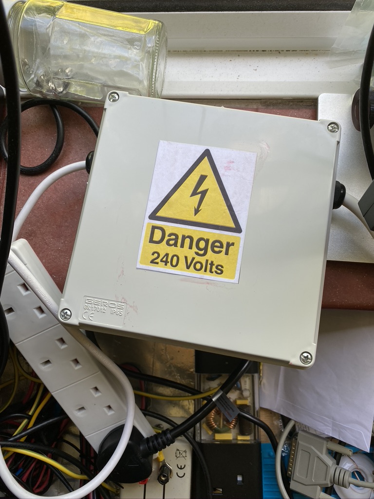
saftey sticker added
installation and safety sticker
Having tested for electrical continuity via a voltmeter, i then proceeded to test with a simple electric lamp which worked perfectly well. There was no issue with the wiring on the toroids or the filter.
I then disconnected my old filter and connected the new filter.
I was immediately impressed that i was now picking out more receive signals on FT8 and Wefax images were incredibly sharp.
cleaner wefax images
I had 4 consecutive QSO’s which had never happended to be before, so was my first time manging a ‘pile up’ of sorts !
In summary for the time and expense this is a fantastic additon to the shack and makes me confident that in terms of power-line RF and QRM I have done as much as I can in terms of mains-filtering.
Thank you again to GM3SEK fantastic blog posting and G8KVM for pointing me in the right direction to the updated design !
73’s and see you on the airwaves soon hopefully !
— Appendix page update ! 🙂
Following Phil’s comments I powered down everythign and re-opened the filter as its been a little while since I closed it up.
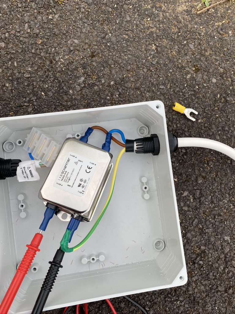
In the picture below, the mains is the cable to the top of the page, this connects to the line filter, then in turn the ferrites connect to the output of the filter. I think I have got this correct based on the source picture !
Source – https://gm3sek.files.wordpress.com/2019/10/capture.jpg – All credits to gm3sek.Pic of filter following Phil’s observations
Whilst mine isnt as tidy, i think it is correct. Appreciate if you can reply to comment Phil 🙂
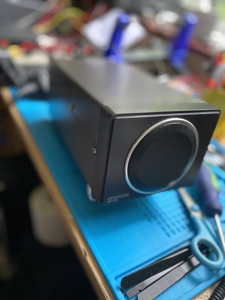
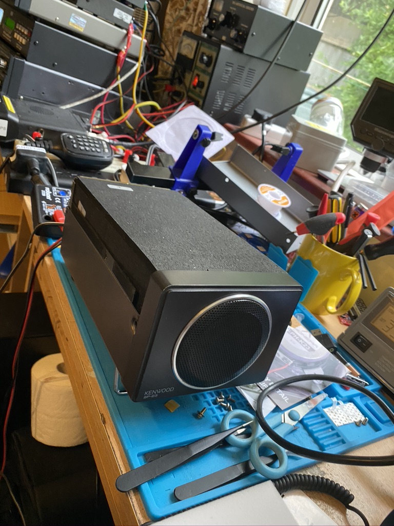
The main speaker on the Kenwood TS690-S is not a bad one. I’ve been using it now for around 5 months, and although no expert, it has been good in terms of being able to listen to what ever made it thru the antenna and to the audio stages of the transceiver.
However, with the addition of the Auto-tuner and DSP, there is quite a bit which ‘blocks’ the speaker. Whilst not muffled, its ironic that I have such a good DSP and not a good external speaker. I do have a very good mixing desk (Behringer X2222) which I use on ocassion to process and amplify the audio from the transceiver, but ordinarily I keep the radio audio seperate from the synths/drums/guitars. Another issue would be managing the sizeable ground loop between mixer and transceiver as the earth/bus bonding isnt the whole way around the ‘shack’ yet.
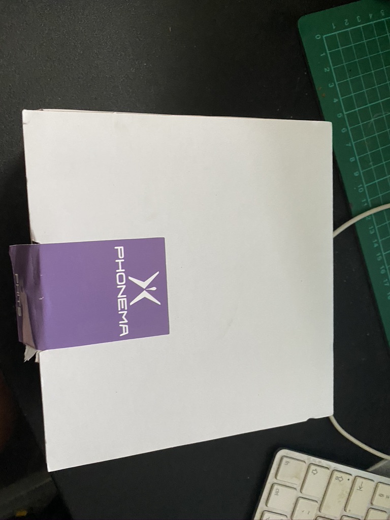
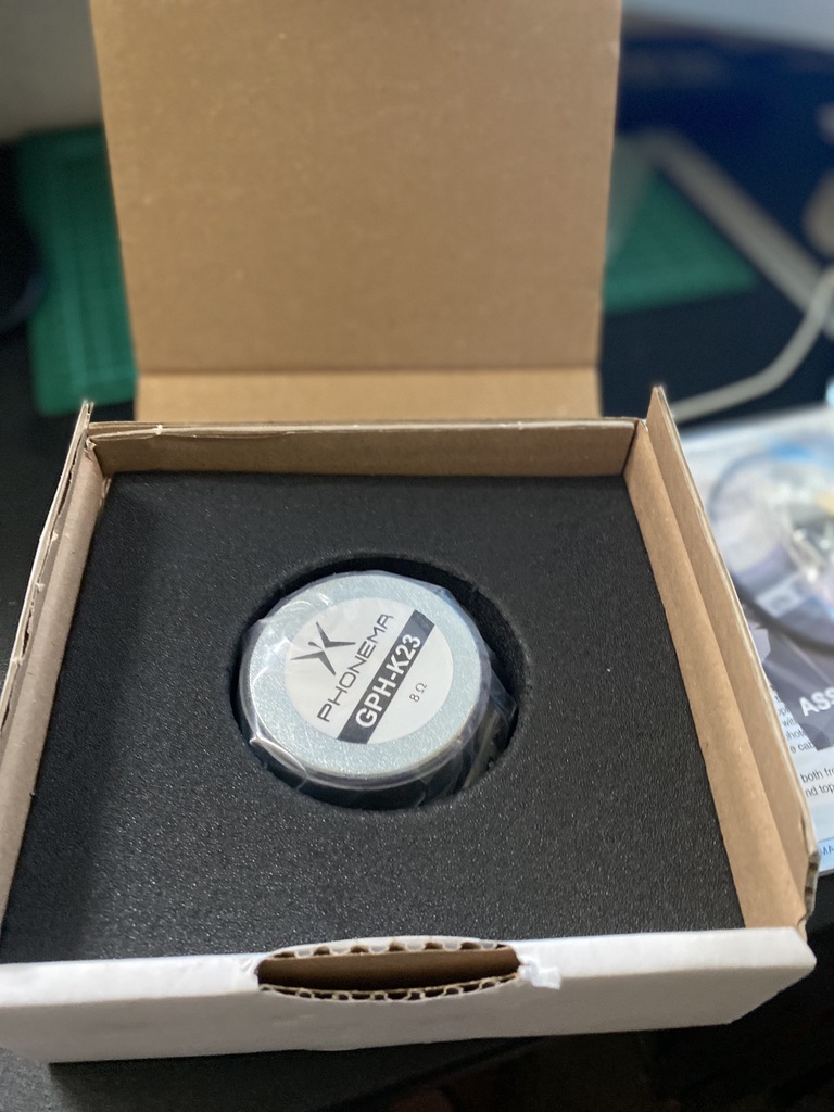
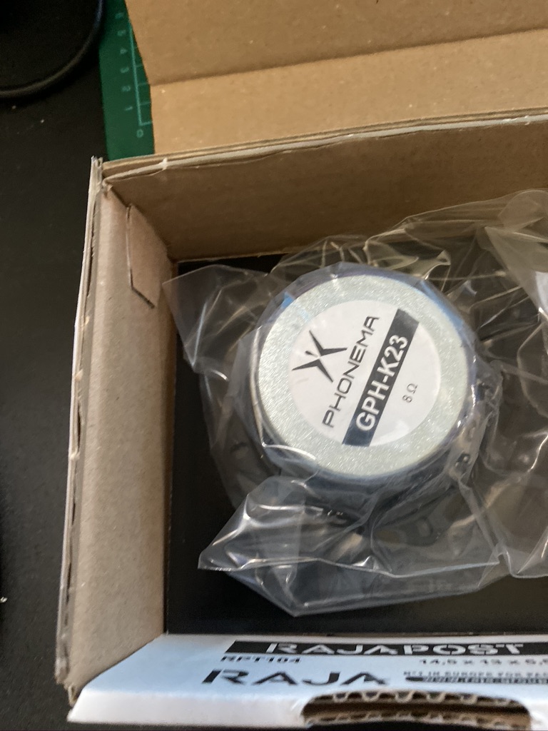
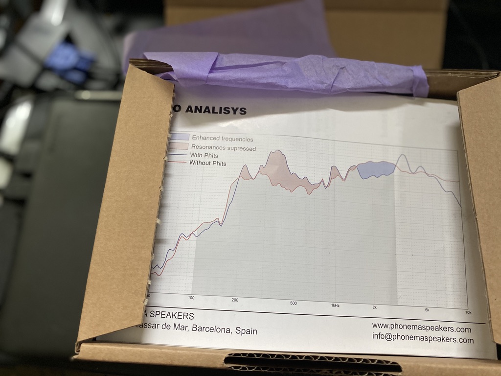
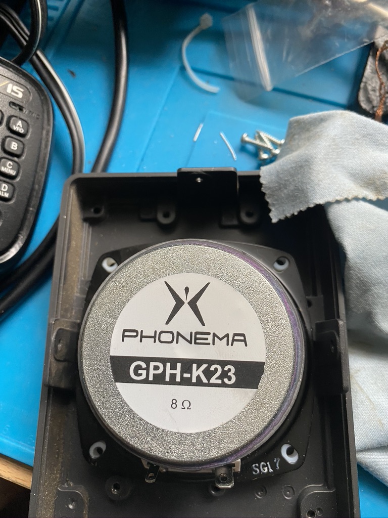
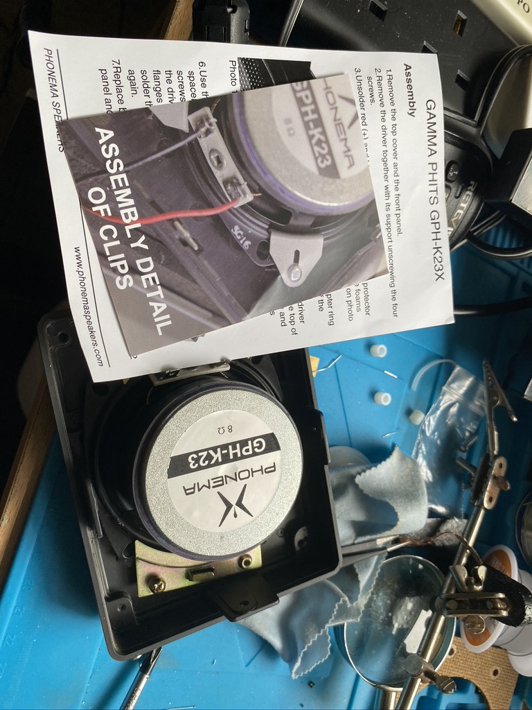
This lead me to search for a speaker for the TS-690s. Whilst not an ‘audiophile’ I do understand a little about speakers, housing and acoustics of them. I was very lucky to find a really great condition Kenwood SP-23 from ebay. The item itself is in incredbly good condition. I cant tell if its one month or 10 years old. It looks gorgeous. When findng the SP-23 I also searched for upgrades to it, this is without hearing it, but I’ve come to trust the reputable amateur sites on the internet, for example eHam reviews of the SP-23 talk about the quality *compared to other speakers* – I guess when you buy a speaker you want it to be the best buck for money. The most often given upgrade was to the GPH-K23X speaker and applying Phonema K23A PHITS acoustic coupling. I ordered both immediately and was amazed that these arrived from the USA in just a few days – amazing work from FedEx.
Having had the speaker for several days un-modded I was quite happy with the audio quailty. That said I still dont do enough telephony work to really say how good it was, and other than the internal speaker have no real reference on what ‘good’ is in terms of HF transceiver speakers.
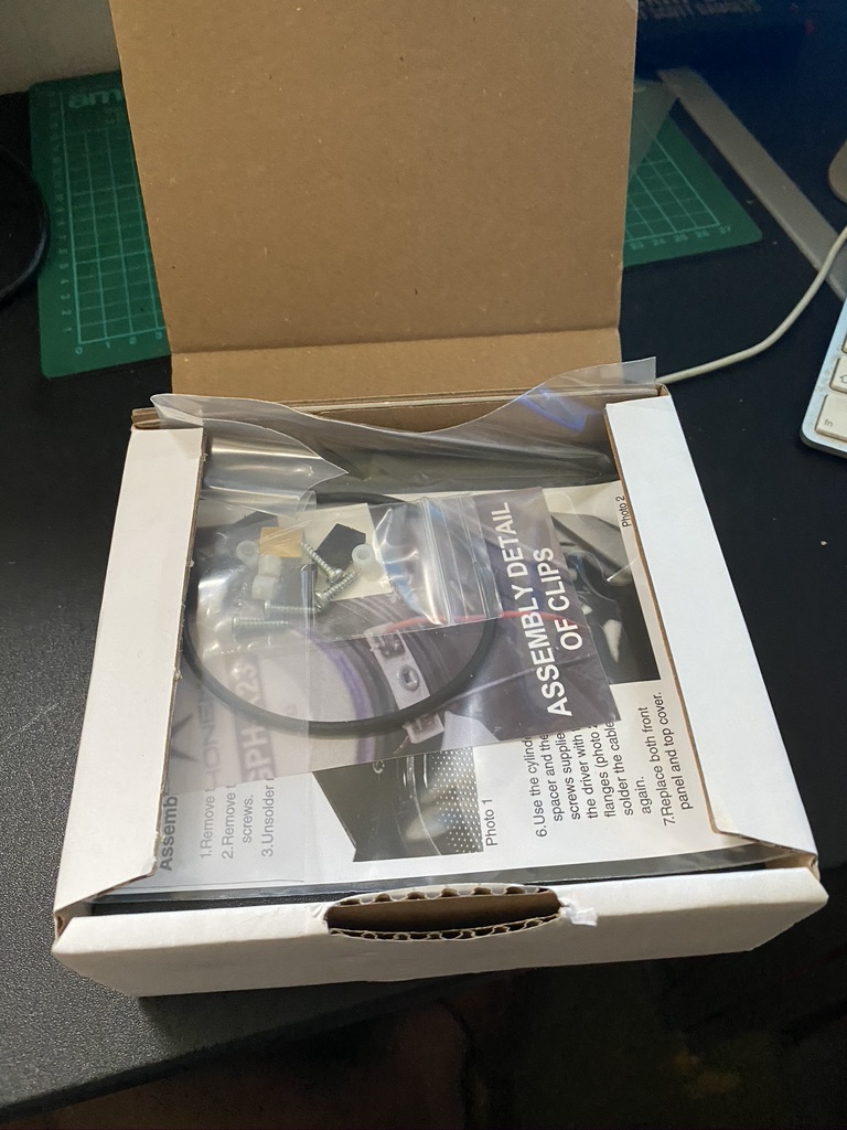
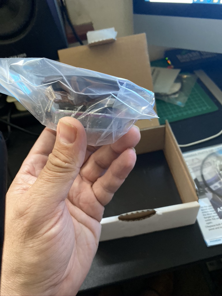
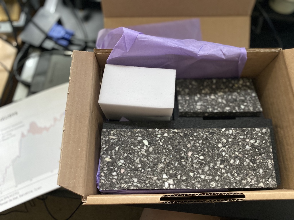
As the kit arrived so quick, i jumped over a couple of other projects to immediatly upgrade the speaker and apply the acoustic foam.
Very well packaged a deent box for the foam
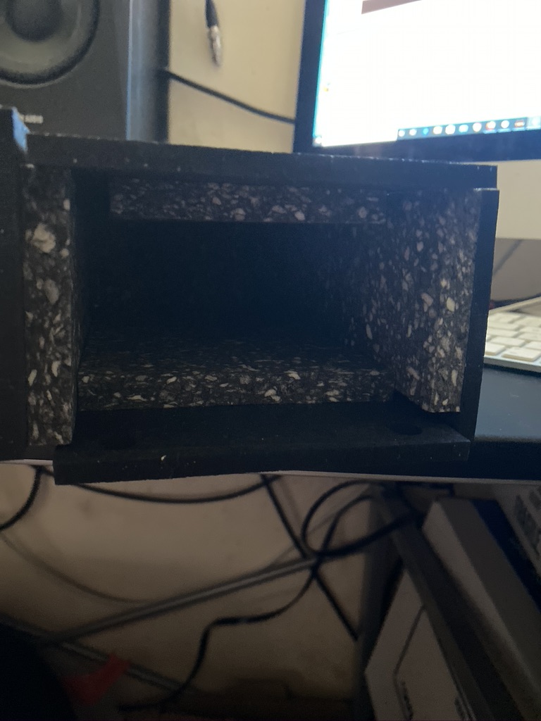
The speaker box is very good dimensions
A manual and parts for mounting the speaker, or not
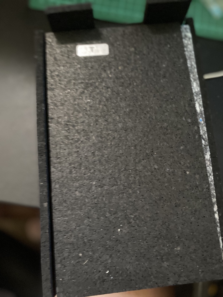
Briliant foam
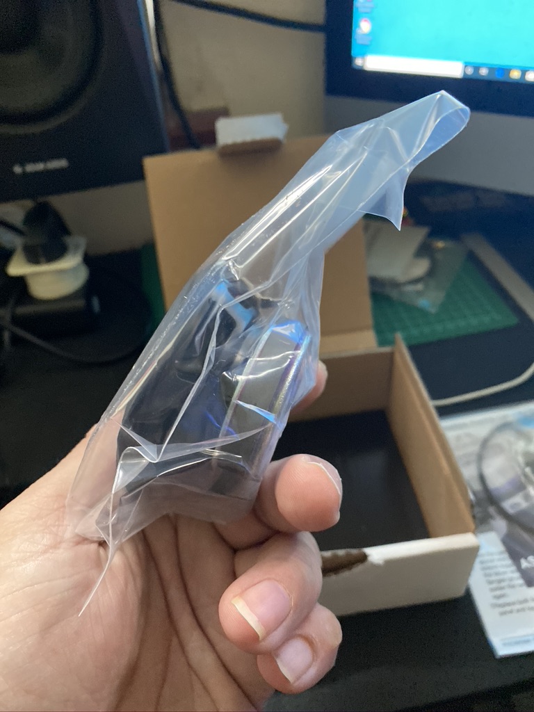
A good bag as well to keep it clean/dust free from factory
further packing under the speaker
parts packed nicely in a seperate bak
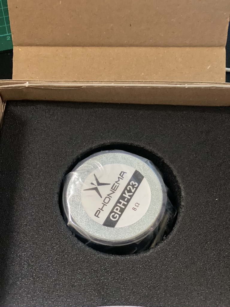
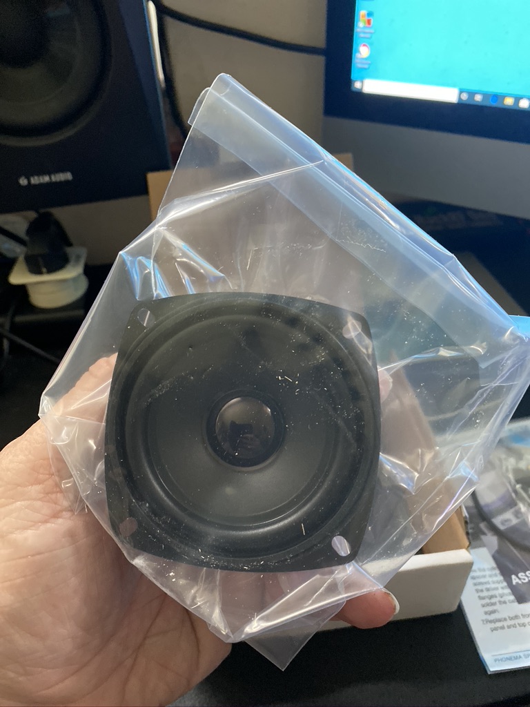
the speaker looks very good quality
the magnet and voice coil look substantial
the foam is very dense
very well packages
even a spacer to keep it tidy – ensuring no bent edges
a useful datasheet
Unpacking the speaker upgrade parts
I was really impressed with how well the speaker and foam had been packaged, its quality throughout and is a good sign that this is a quality purchase.
one last look at the unfettered SP-23
a clever way to mount the speaker imho
removed speaker
woah its big
side by side comparison
so wheres it gonna sit ?
how does that fix in there ?
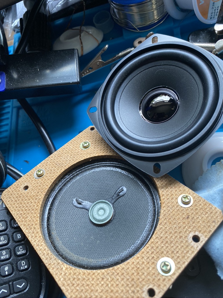
Removal of original speaker and first attempt to instal GPH-K23
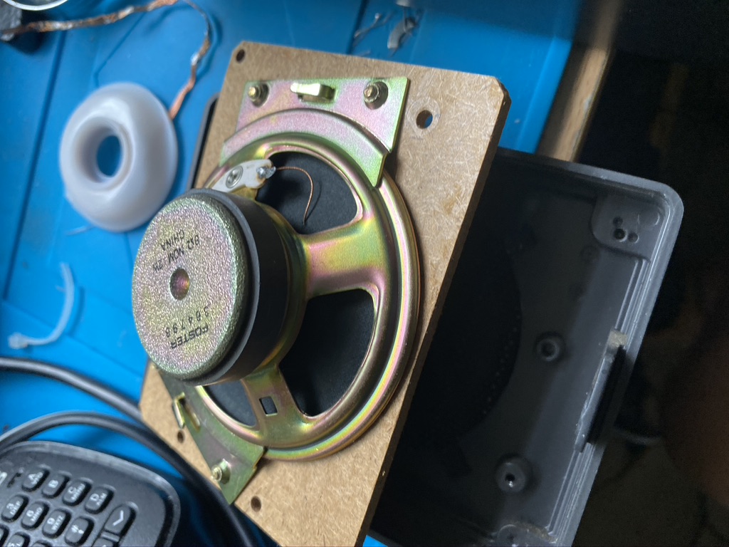
I am always slightly relectant to make changes to orginal equipment, but when I do I make sure i can recover it back. In this case i carefully de-soldered the orginal speaker. I did have to cut a little of the positive wire as it has been wound so well, but it was a minor inconvieane.
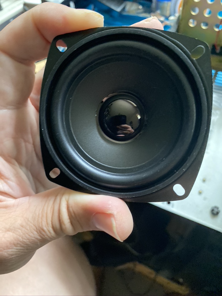
I was then able to start trying to work out how to install the new GPH-K23. Reading the instructions it discusses a bracket and furthermore has pictures of ‘clamps’ which are not visible in either the kit or in the existing speaker. I was slightly confused how this could happen, give this speaker is designed for the SP23. In the website for the GPH-K23 is describes a ‘plastic’ front version of the SP23. Mine is very metallic. With that i was somewhat perplexed on how to mount the speaker, especially as I had now de-soldered the orginal speaker just moments ago.
how does that fix in there ?
trying to use tweezers wont help
this picture looks nothing like my speaker cabinet
improvise..
adapt
overcome
succsses ?
speaker cone very central positioned
fitting the GPH-K23 to a metal-front SP23
I was undettered by the fact that the instructions and mounting didnt match. There must be a way to do this. I had kept the old parts safely, ready to be placed in the SP-23 box so that they are there for future records and changes if required. I examined the brackets which held in the orginal speaker. The backing card was too small (diameter of hole) and too thick (widness of backing card) to mount the new speaker on.
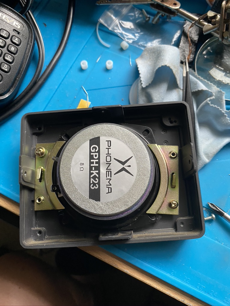
Looking at the parts I had and the design of the case, there was a possibility to use the ‘brass’ clamps from the speaker back to hold the new speaker in place. I tried out the existing screws to check a good fit, and sure enough i was able to use the brass/copper mounting plates to hold the speaker in place !
Looking from the front the speaker looks very centrally located.
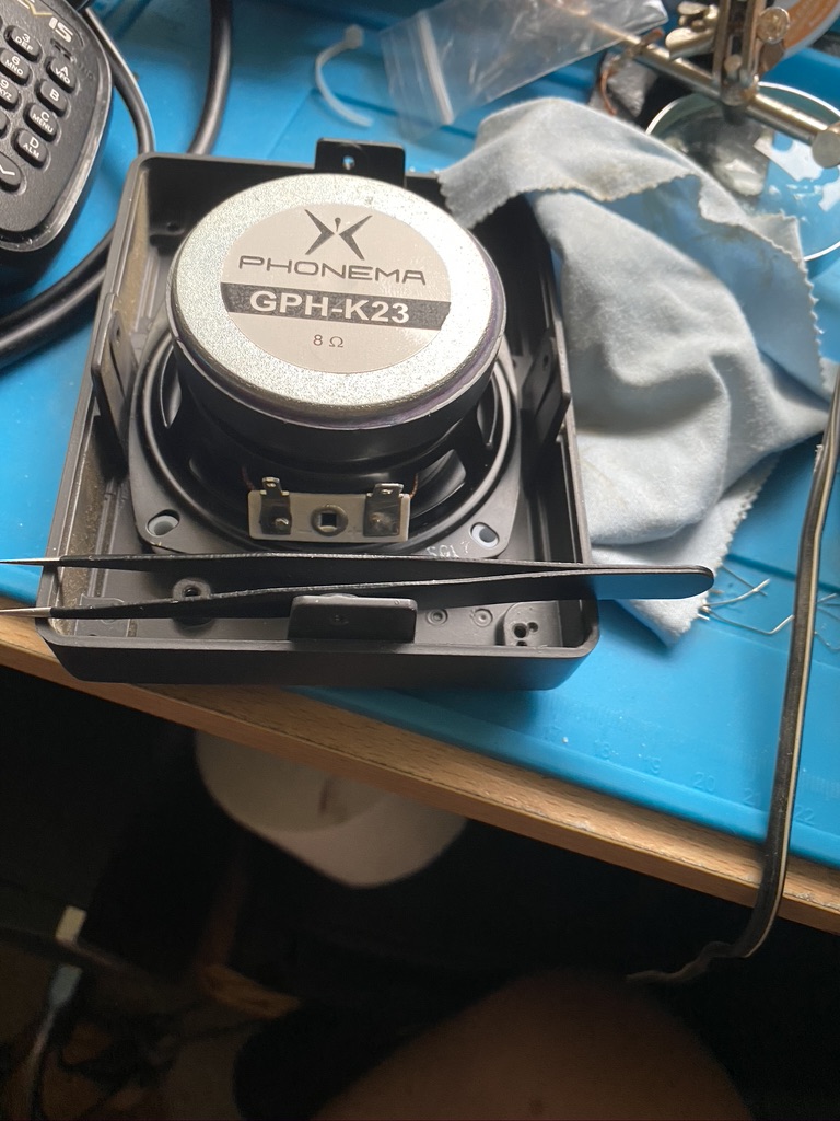
Foam added
and back in the stack!
the isolation foam makes the speaker a good weight
The foam fitted really well in the speaker, i was very impressed with the cutting and density of the foam. Getting the case back on required some real effort to it fitted, but on it went and back in the stack it went !
Now, i think its very subjective on how good something sounds, so here it is in action.
Sp23 listening to broadcast radio and the 40 meter band
I for one was very impressed and felt the additonal parts did bring something to the speakers audio clarity. I would recommend that anyone that does have the SP-23 to get the coner and baffilng. I had to choose between one or the other, start with the baffling !