The DX Commander comes with 100m of very good wire, which is enough for making the 4 element (40,30,20,17m) vertical and some for radials. Having already bought 50 meters of wire for 80m I was still down on the count for both radials and the ‘all band’ – having complete the ‘all-band’ construction it was now time to sort the radials !
With the orignial wire and radials I had around 28-30 radials, which whilst much better than only 1 and improvement on 15, is still slighty short for 80m and also more radials=higher Db out at other wave lengths.
So what is the science about radials ? The Calum has a good video to help, and the references are very good, so I’ll put that here first.
https://www.youtube.com/watch?v=qVG1jevrXaI
Radial videos from Calum
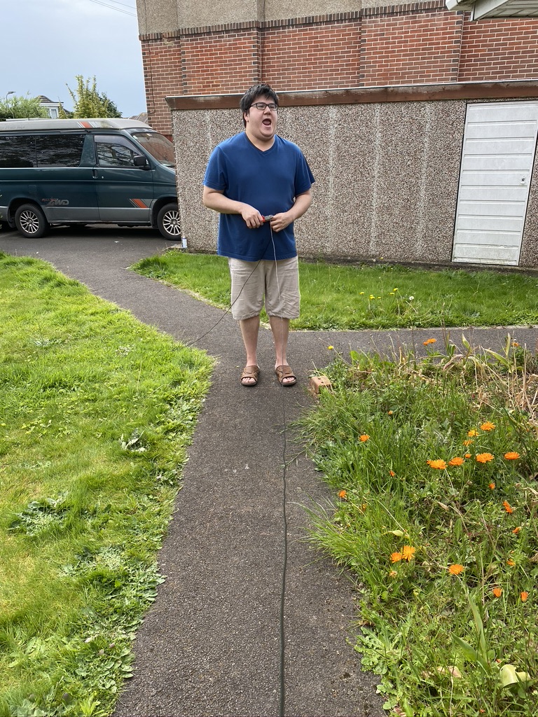
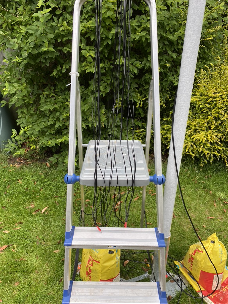
So basically adding radials helps (I did try to find a video of a person fallilng off a boat getting onto a pier, but was getting to distracted…) I took 50 meters of wire (the same type I had use on the verticals) and set about making into 3.5 meter lengths, which some great help from my son Paul which saved my back alot in terms of getting up and measuring and cutting !
pull and cut thanks Paul 🙂
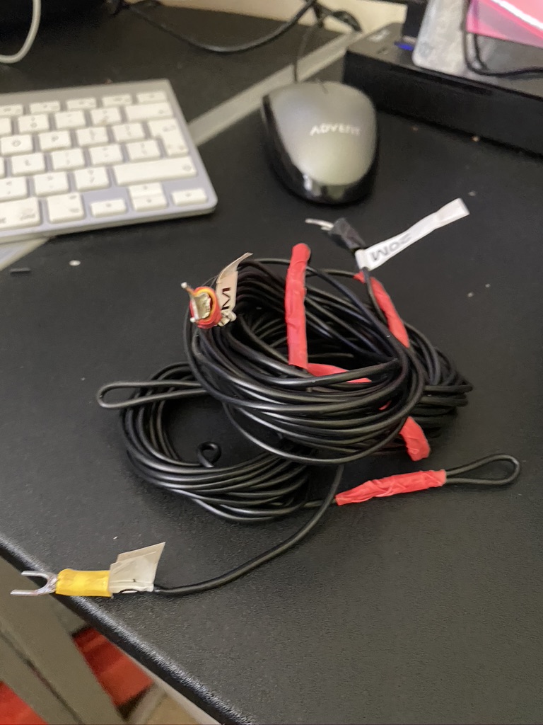
it started as 50m, it became radials
cutting radials
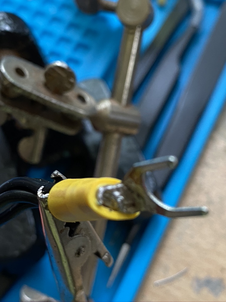
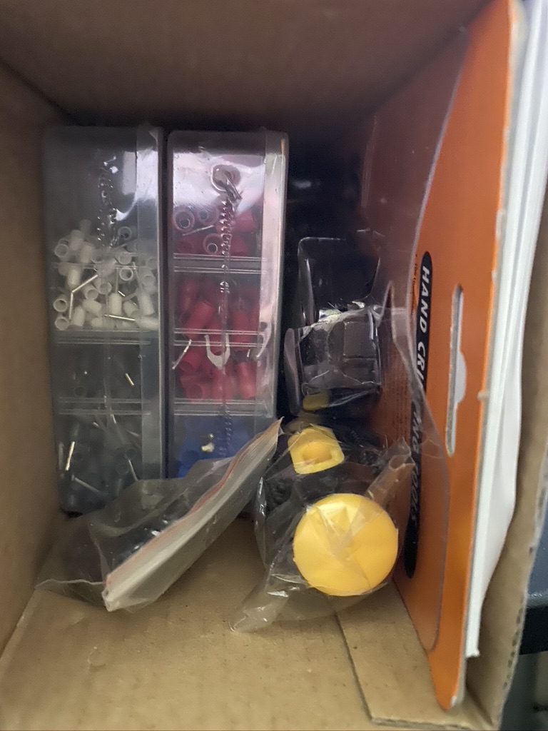
With the cutting done, it was time to return indoors for strip, crimp and solder !
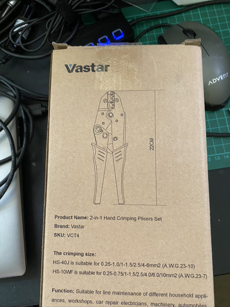
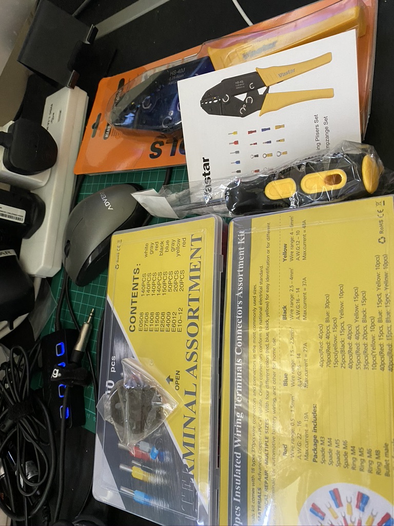
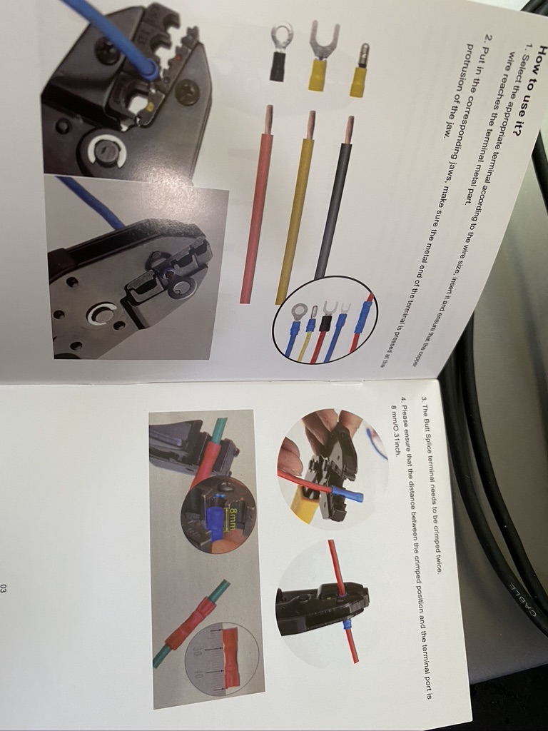
new crimper doing a grand job
solder together, solder the crimp
strip, crimp and solder (*2)
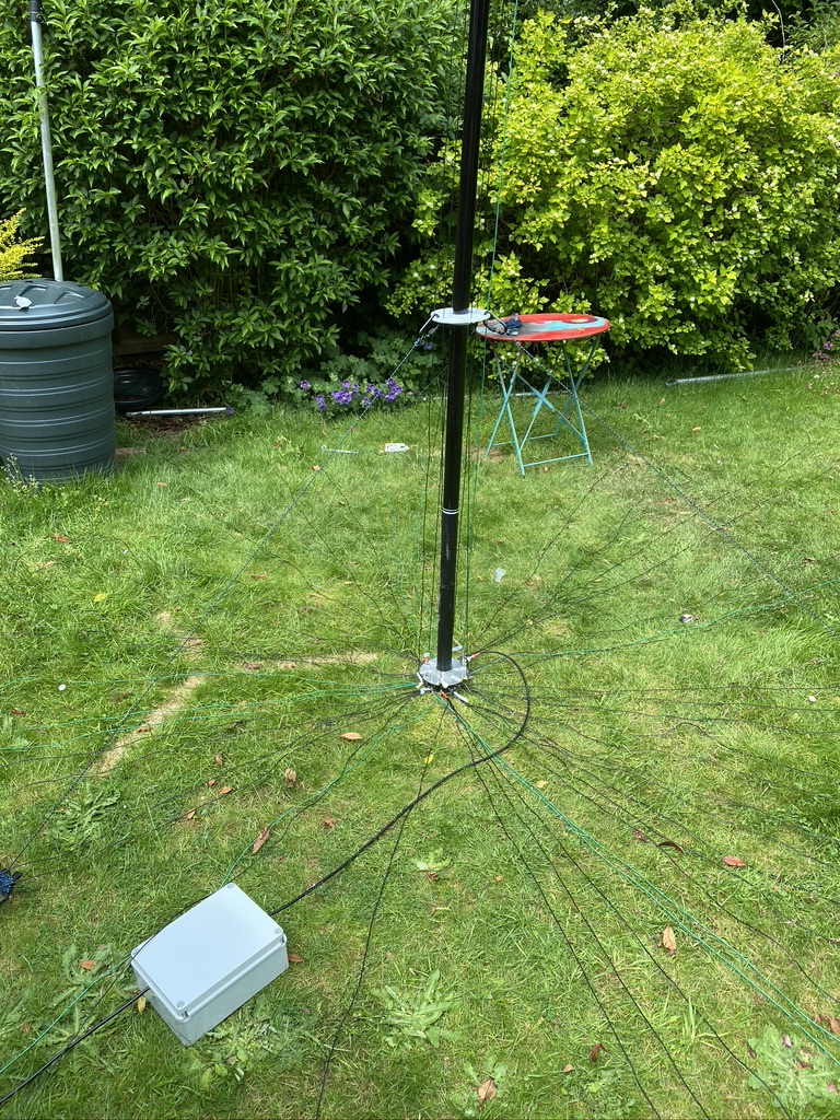
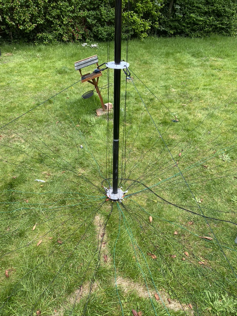
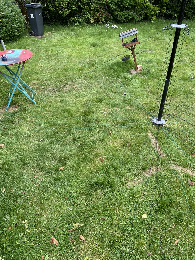
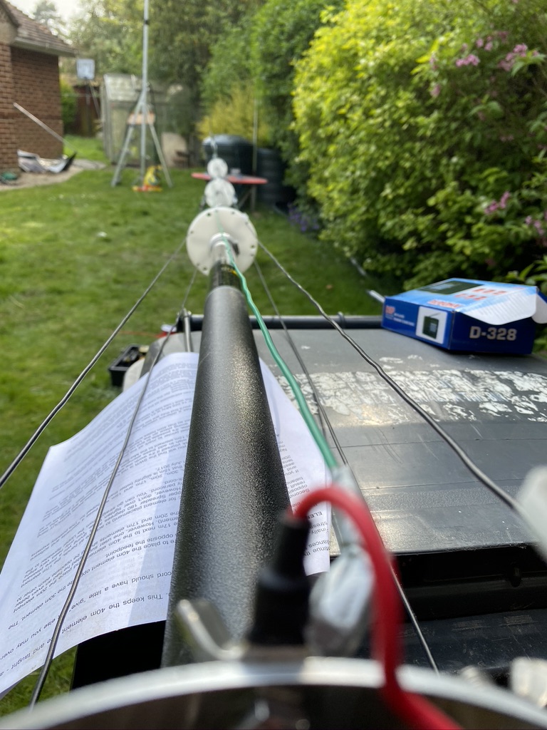
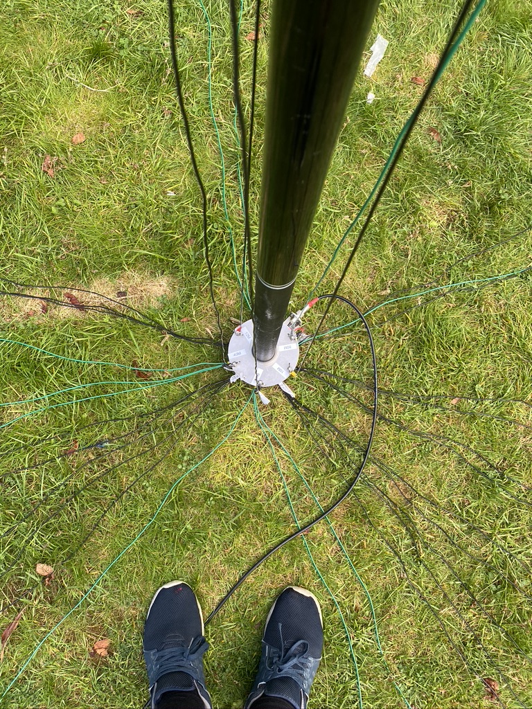
I then returned outdoors to install the addtional elements. I doubled up on one existing element, but had a pretty decent fan of 3.5m wire elements going on now.
a nice spread
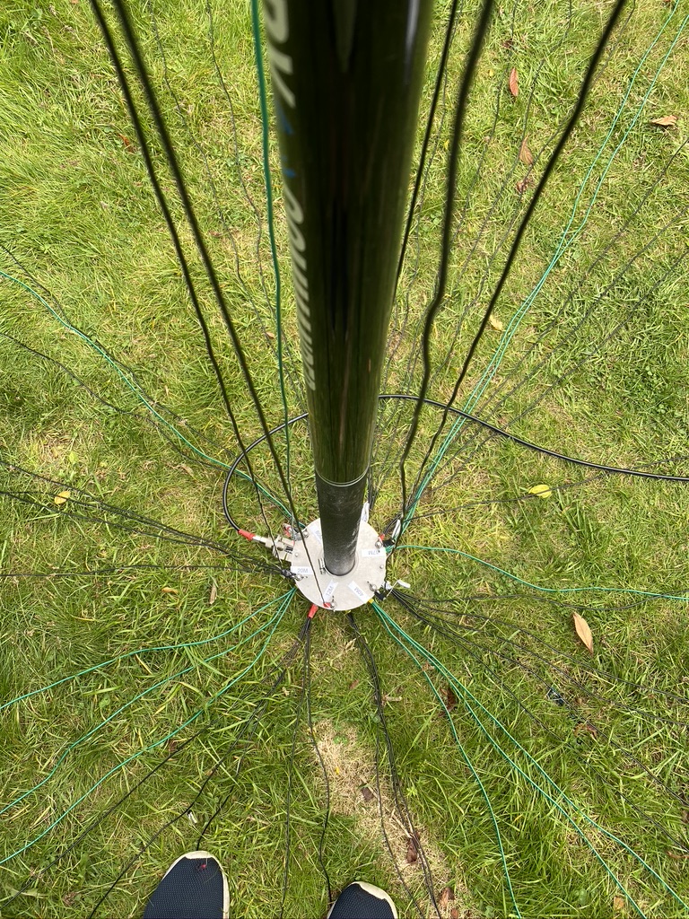
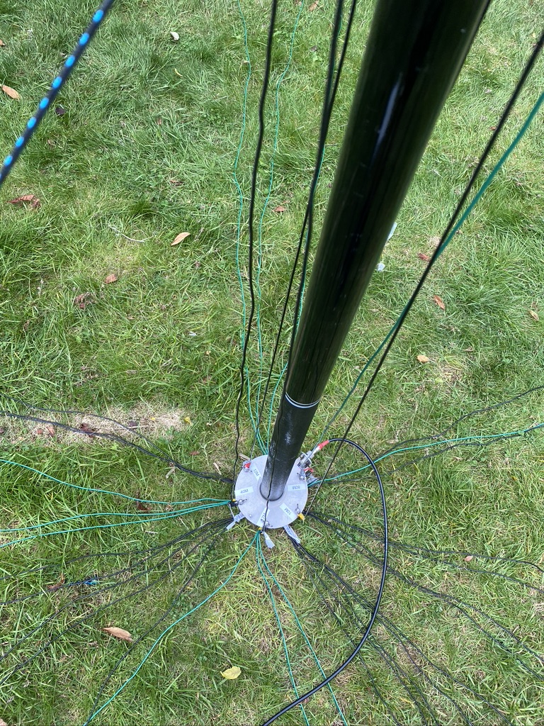
view from the base
keeping it tidy
gaps to fill
now with added elements
adding elements
I’d need to an exact recount (will do so later) but I think I now have enough radials to accomodate the 80m vertical.
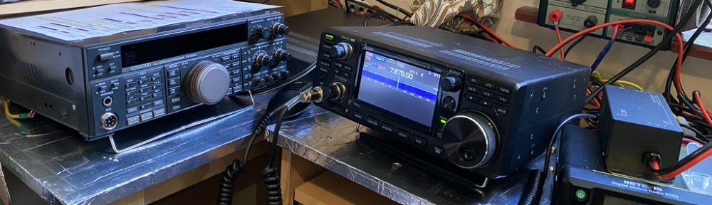
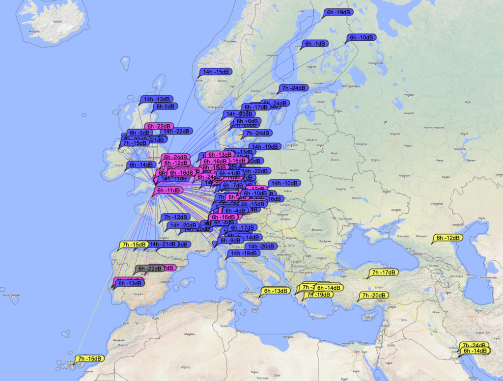
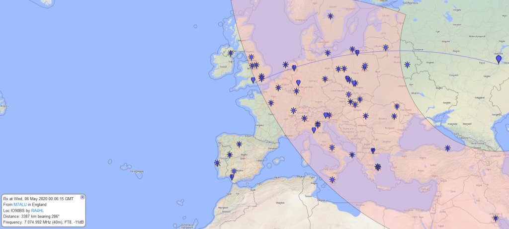
With having added the radials it was time to test ! For this I use FT8 as it has a great map and includes a signal report when a QSO is complete.
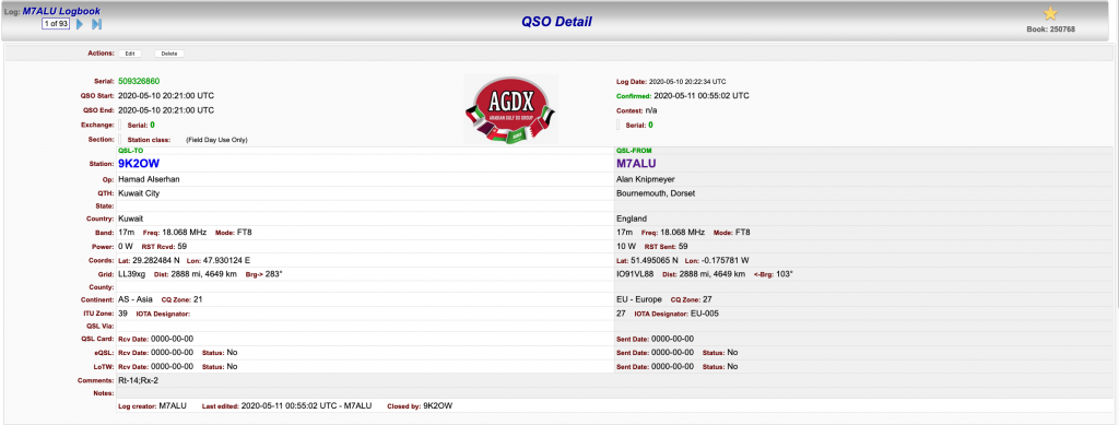
Reaching Kuwait on 17m
I was now reaching Kuwait on 17M and even better was that I could see the call sign in my WSJTX screen – i had to give it a try ! And sure enough within a few minutes (this guy was was getting alot of QSO’s in) I had made contact !
Contact with 9K2OW in Kuwait – a staggering 2,888 miles on 10 Watts of power !
So i think i could continue to add more radials, but for now I’m happy with how the DX Commander is performing and the radials are performing their function. I will investigate more ‘science’ based ways of radial performance, but his helps for now !
So its been a bank holiday here in the UK and its allowed me to work on quite a few different things (including re-wiring the Mazda Bongo door looms). When I got the DX Commander it came with enough wire for 4 verticals and the radials to support it, but I purchased some more wire from Radio World, namely the Watson Radio Products EQ Equipment Wire which goes for 40 per meter. I used Radio World as I had other bits and bobs coming from them as well, and my word, they are so QUICK to deliver (UPS Everything !).
I checked from the list what additonal wires I would need to make up., in this case only the 10m and 12m. Having learned from trying to measure the wire indoors I now measure all my wire outside. I have 3 meter workmans metal tape which so far has done me brilliantly in getting accurate measurements.
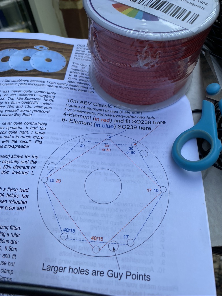
So the first part was to obviously lower the mast, and then remove the existing wires, Going from 4 to 6 requires adjustment as per DX Commanders docs (pg 2) here.
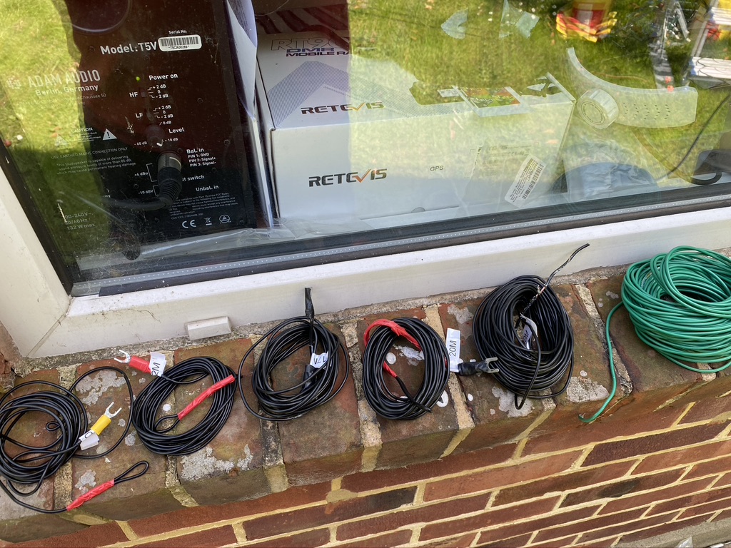
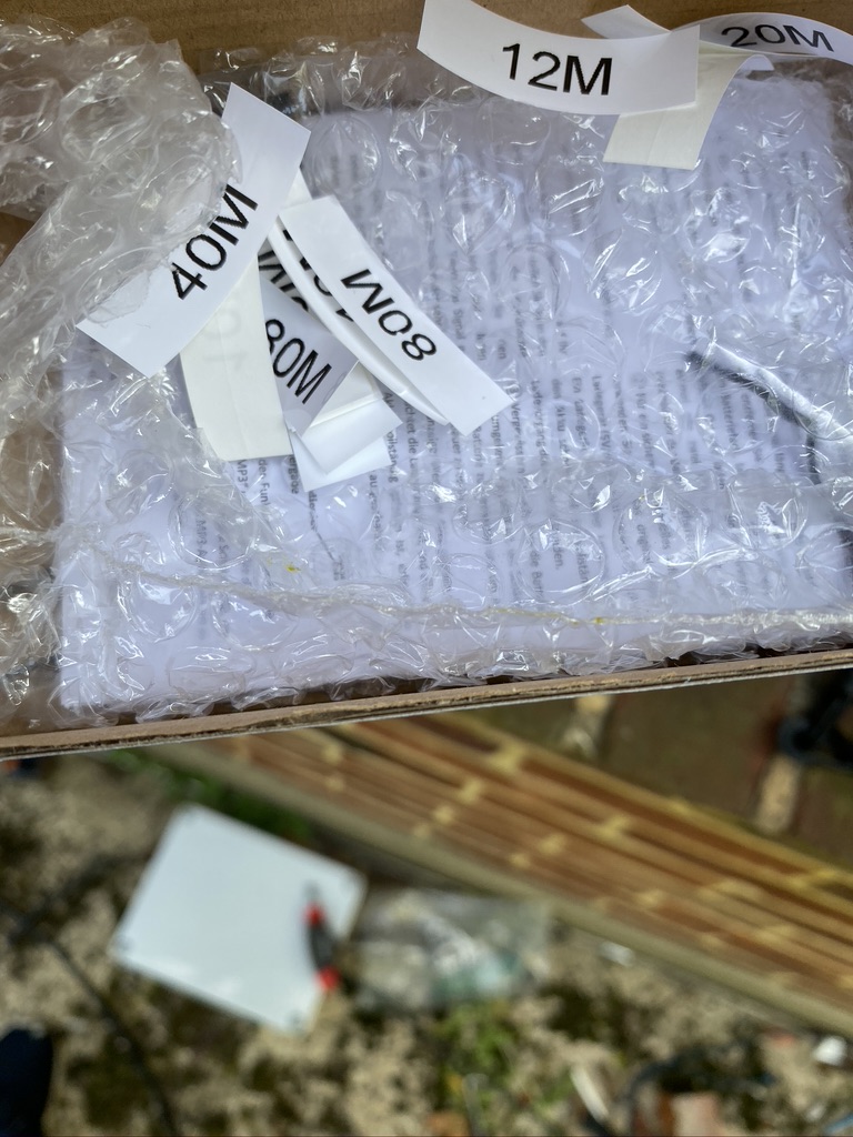
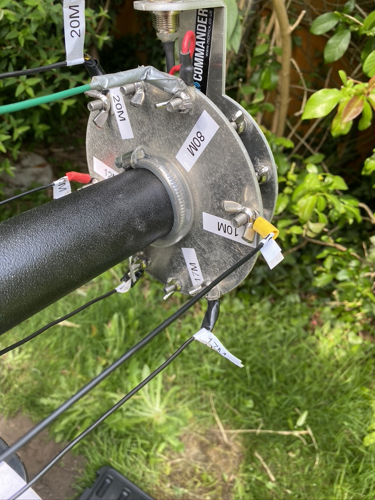
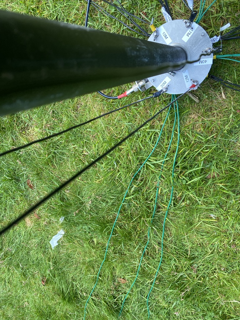
I also reprinted all new labels, removing the existing ones. One thing I didnt do orginally was to put labels on the bottom plate, so this time I would ! First I organized the cables so they was easy to pick up add, not having things on the floor and in a mess really adds to health and saftey when doing this kind of work.
wires in respective order of frequency (10,12,17,20,40,80 – the long green monster!)
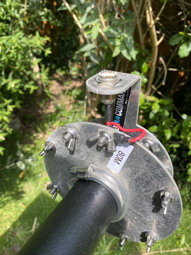
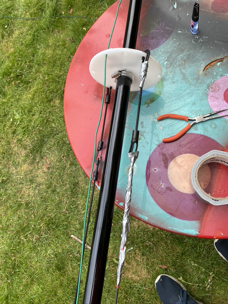
With the mast lowered I followed the instructions and relocated the SO239 feed wire and the 80m connection
movement of feed wire and labelling up
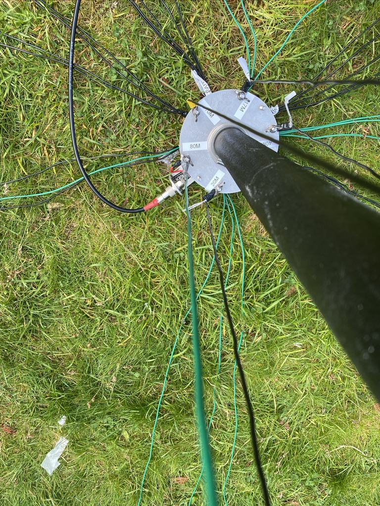
What really helps is the DX Commander stickers. On my spreaders i do them so that they should be aligned when looking down the mast, this gives me a good point of reference.
To start with I just feed the 80m wire up to where it would be for 30m and taped it down. I then worked around the mast feeder positions adding labels as I worked in each new wire.
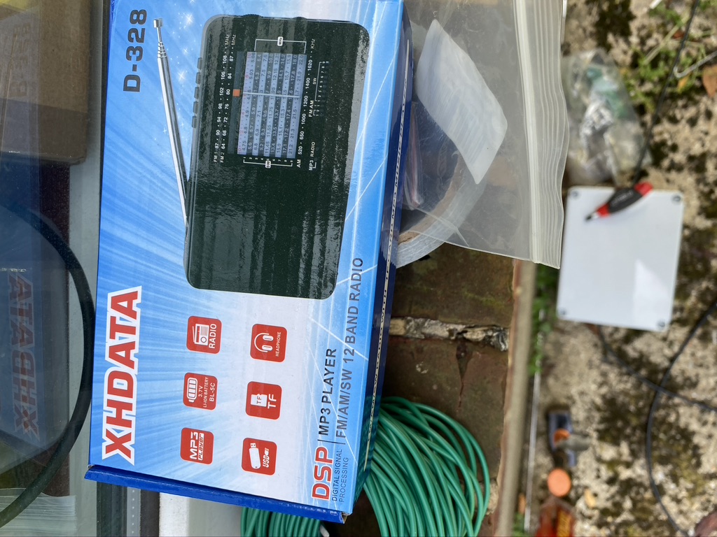
its not just a great little radio
its a box for all the stickers!
keeping the stickers safe
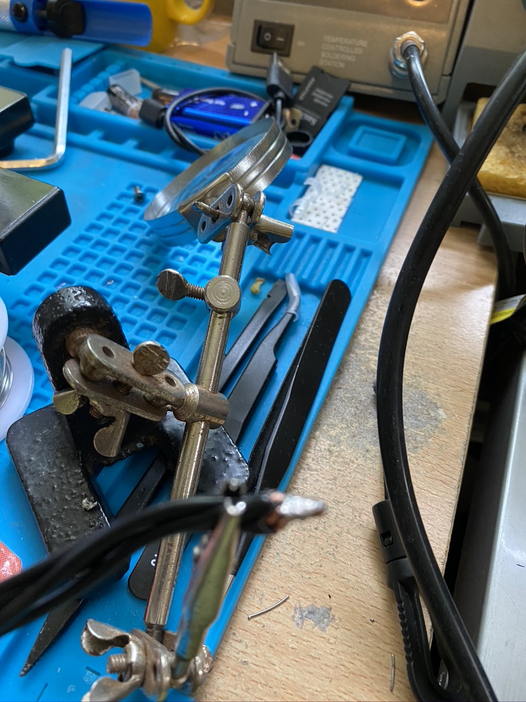
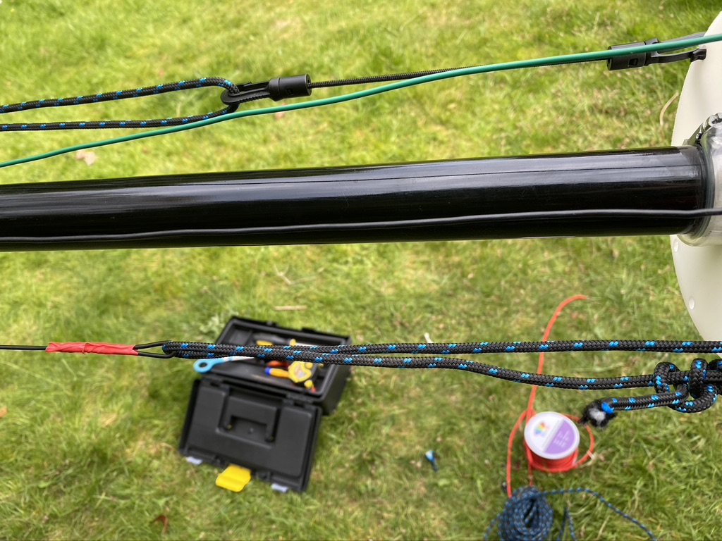
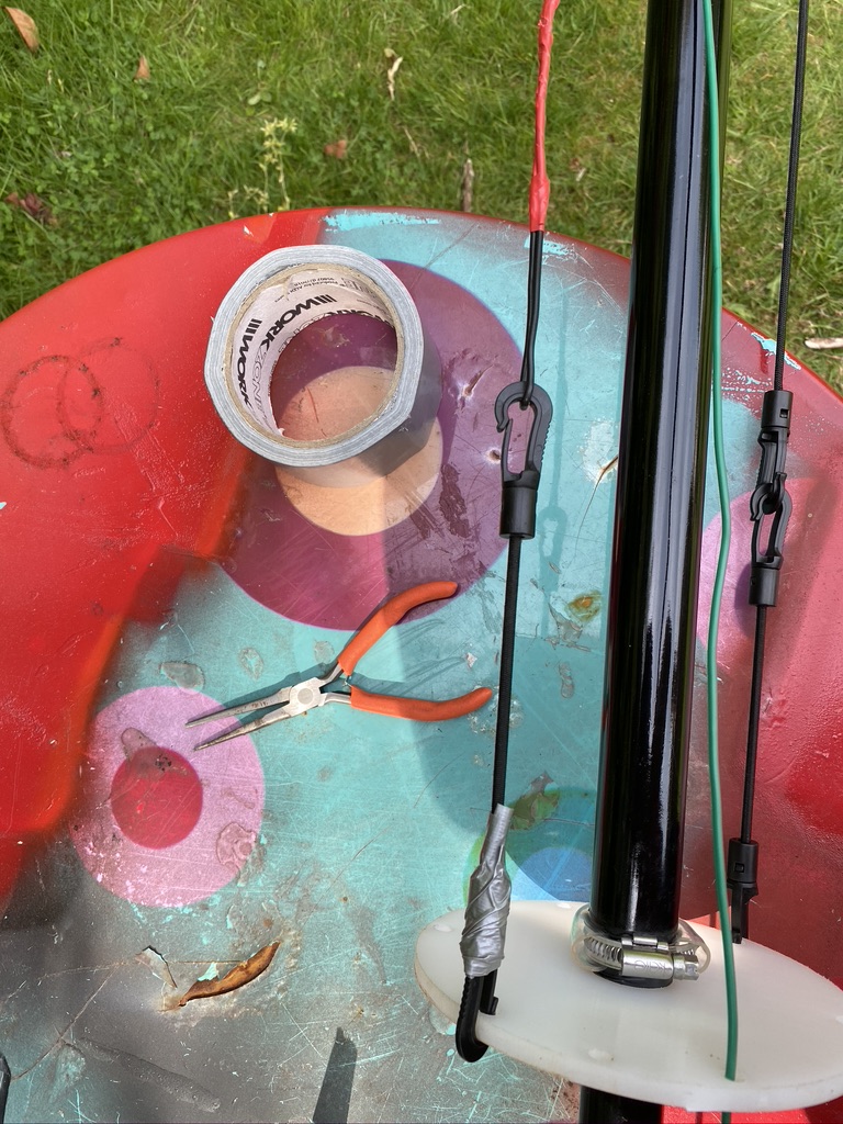
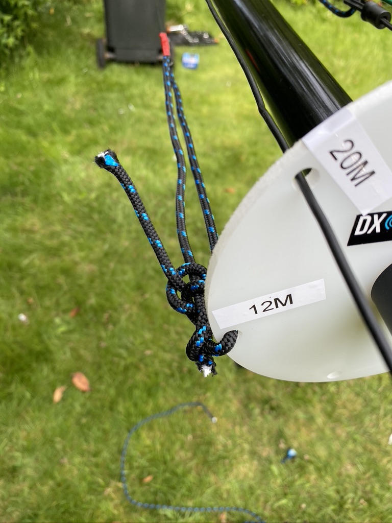
Now the DX Commander/Calum does say that the clips used on the paracord are hard to undo once set, as I found. Having to try and extract one, manage to break a clip, and I had no spares. So, i thought, well superglue it is then ! With using the YOCTOSUN Hands Free Magnifier, i was able to get it to glue pretty much back on. I was then with the existing cut paracorde and elastic cable to add the other elements which required some vertical tensile strength.
repaired clip holding out
loopbacks doing their job
some additonal ‘temp’ fixes
12m, tied directly to the lower guide/spreader
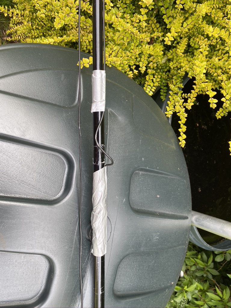
I continued to add all the elements and was happy with the tension and how tidy they are. I also took some time to put some tape around the clips where sometimes the wind will blow and wires get caught in the juberliee clips. As I’m not taking the mast down and collapsing, this wont effect me in the short-term.
nicely labeled plate
tidy going up
some ‘fettling’ with tape for now
wires in place
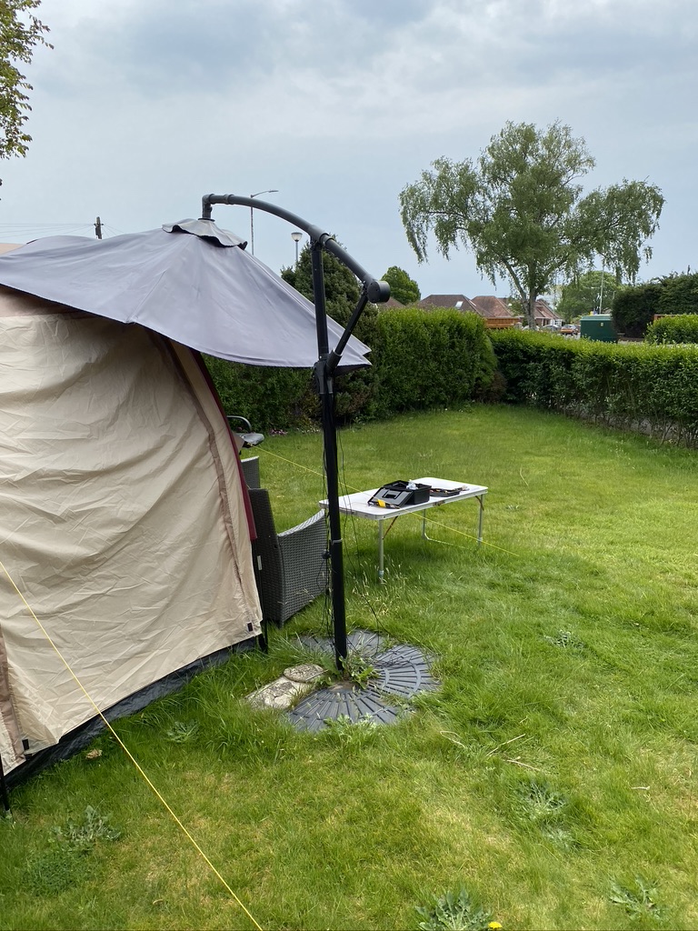
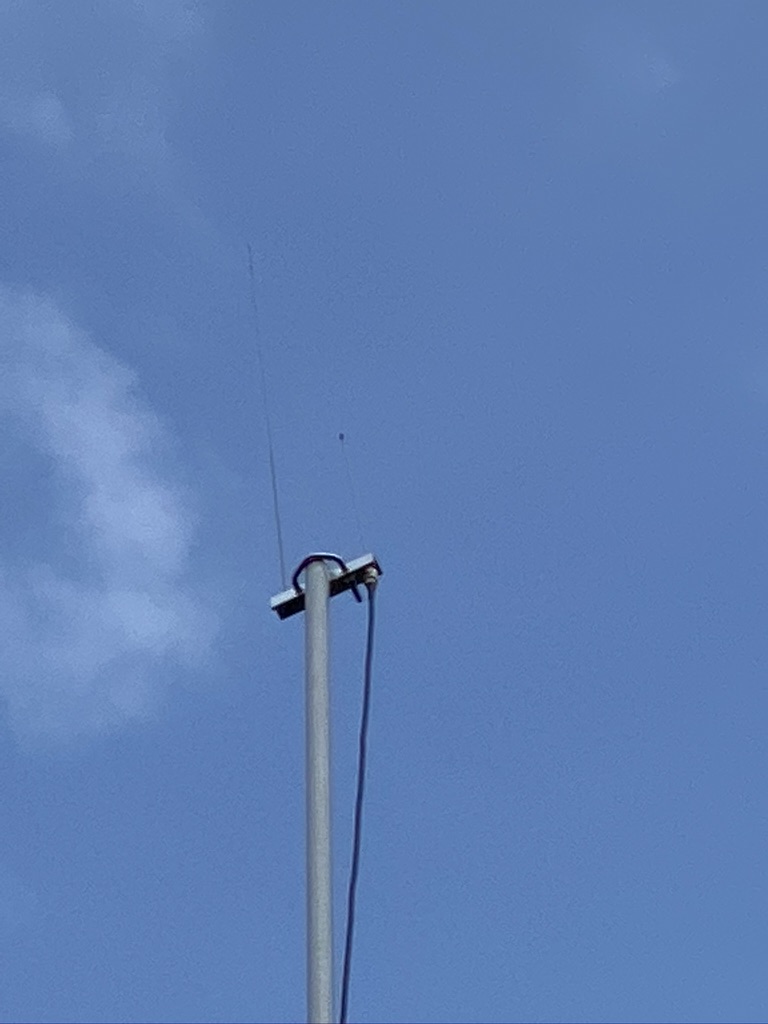
With assistance from my son, we got the mast vertical and I could start adding the existing radials I have. I add the radials in a N/E/S/W layout starting from the feed point, and adding where i have capacity. I also done a ground-visual of the 2m/70cm with my iphone (10x max zoom) and could see it was in good shape up there after I had raised it on Friday.
approx 28-30 radials
spreading them out i go N/E/S/W, then fill the gaps
A quick visual on 2m/70cm antenna
radials and a visual of the 2m/70cm mast
Testing and Results
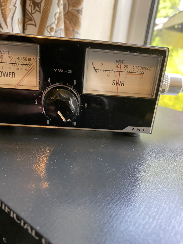
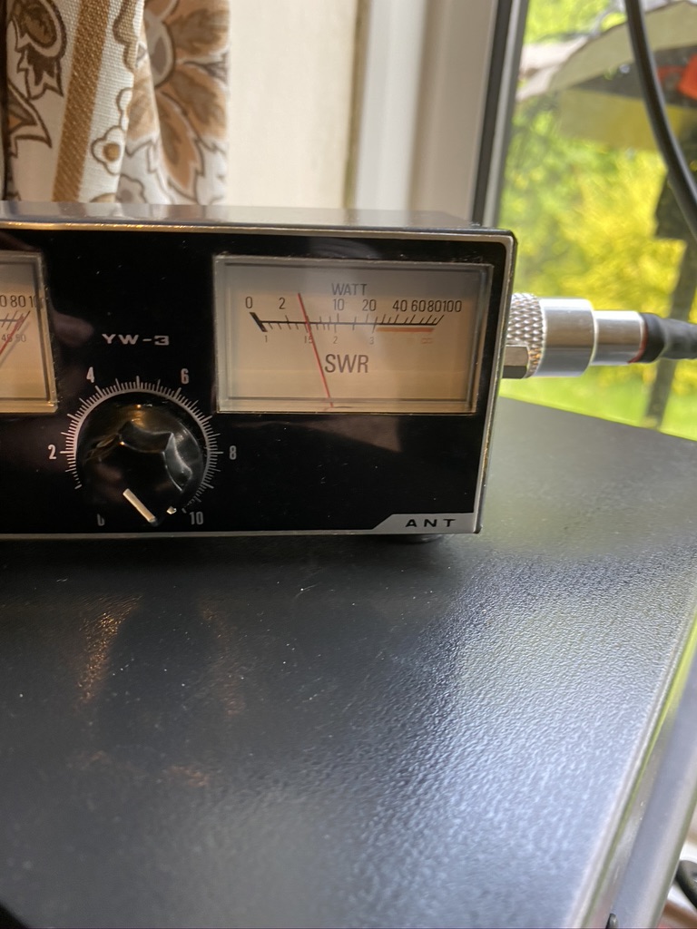
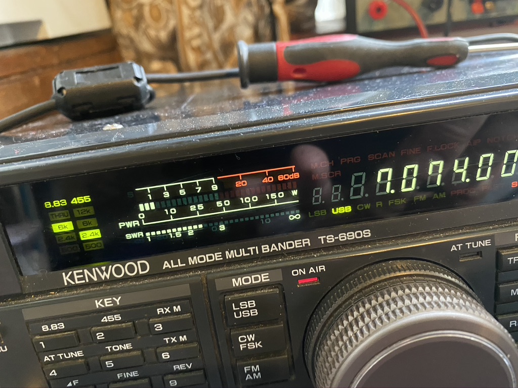
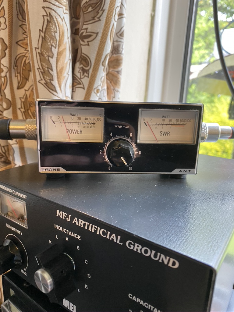
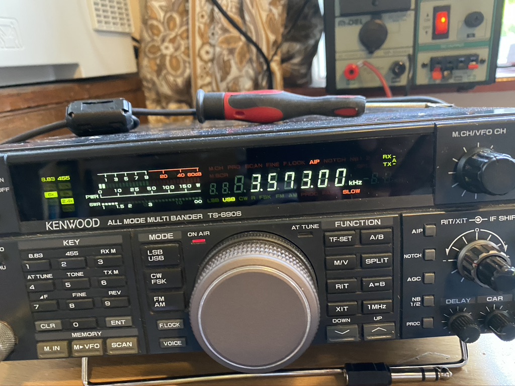
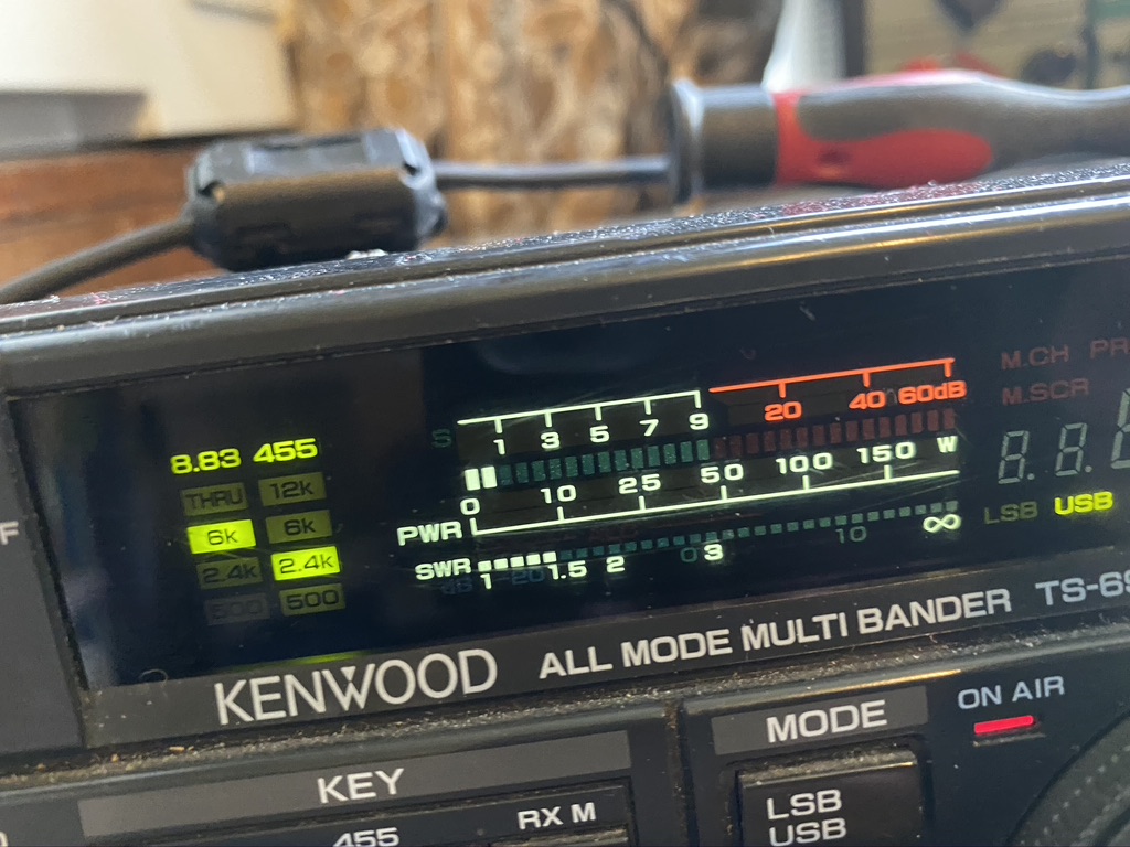
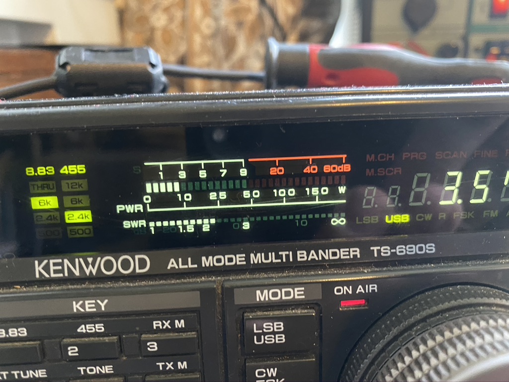
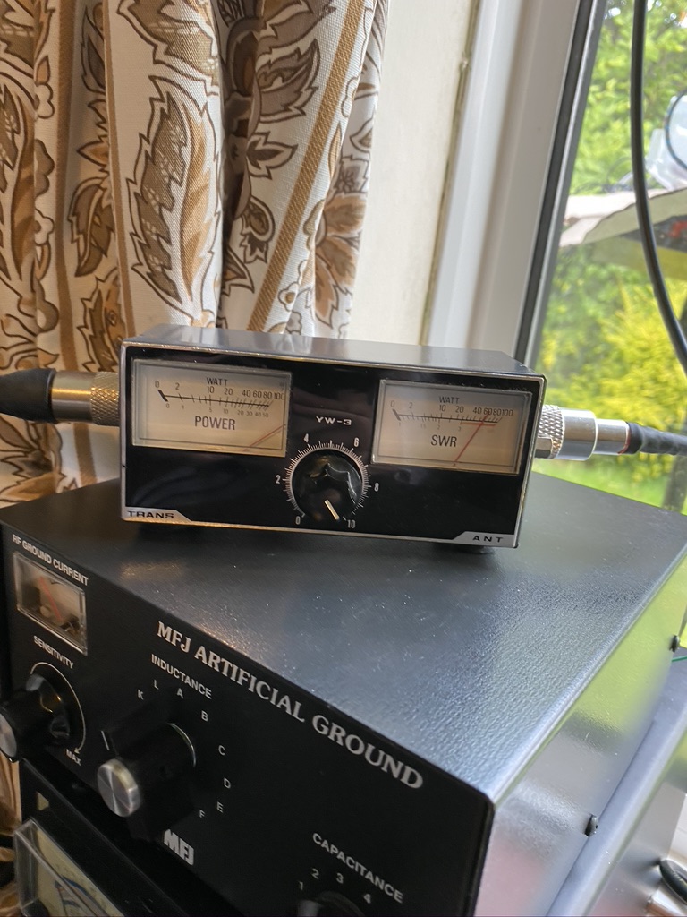
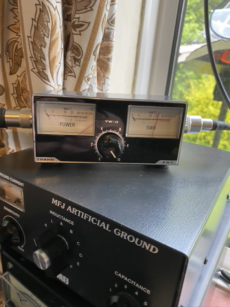
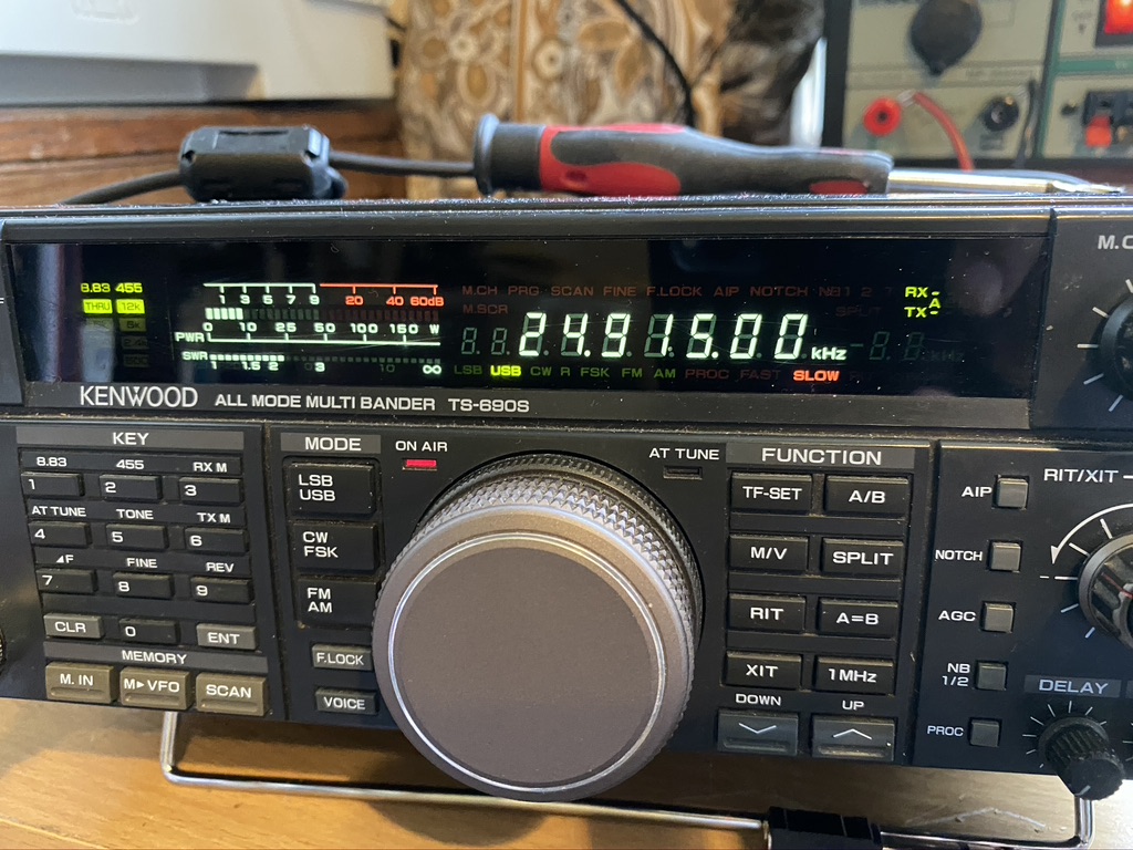
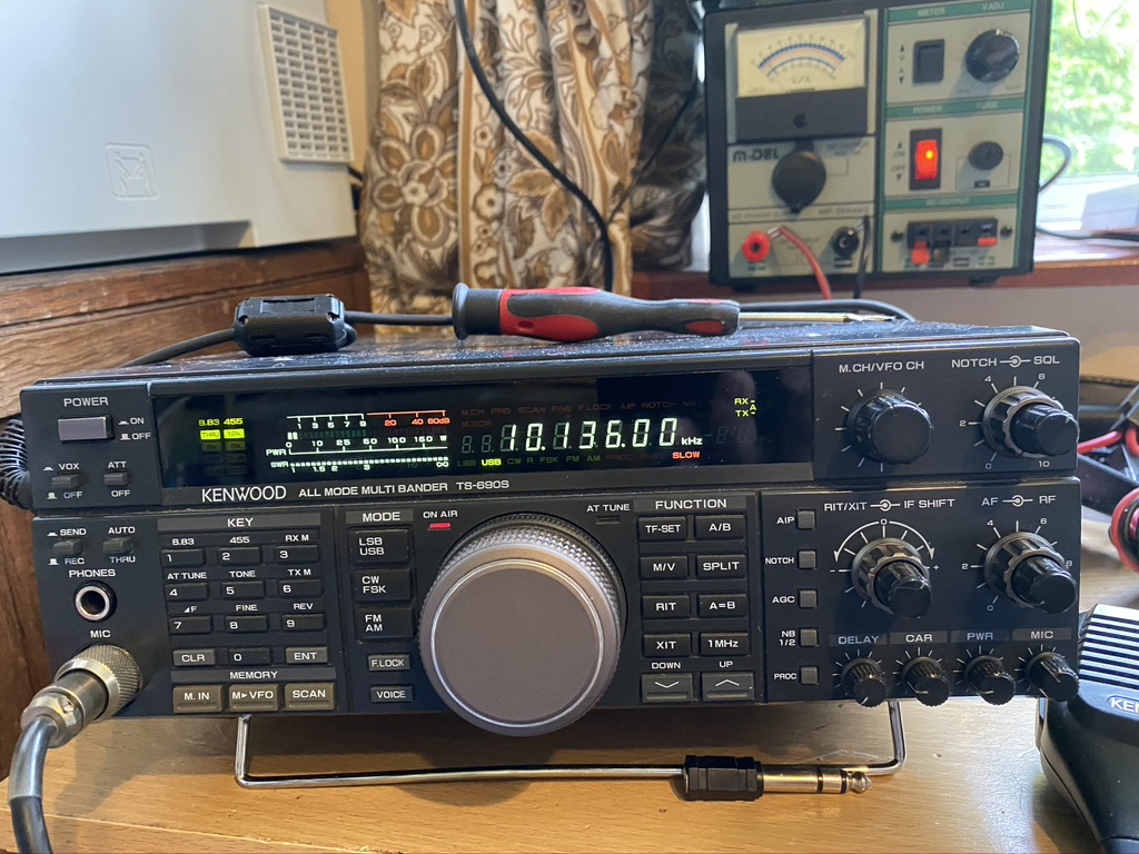
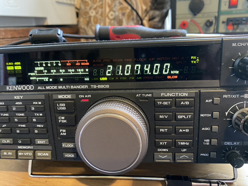
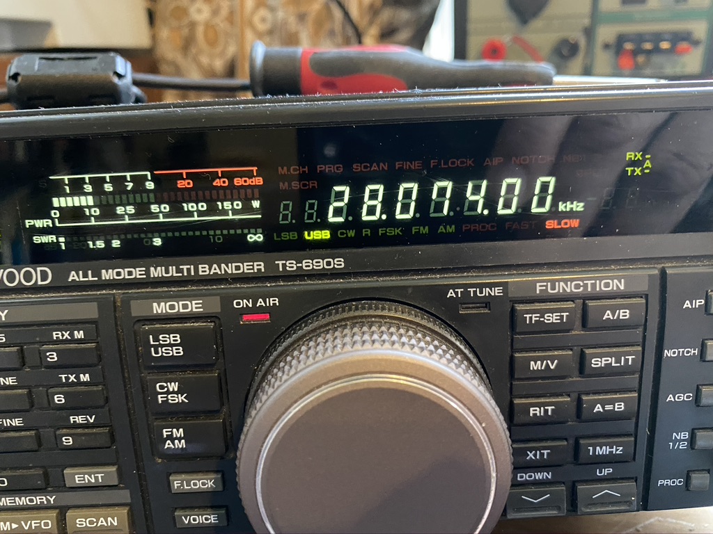
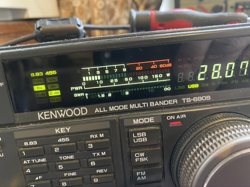
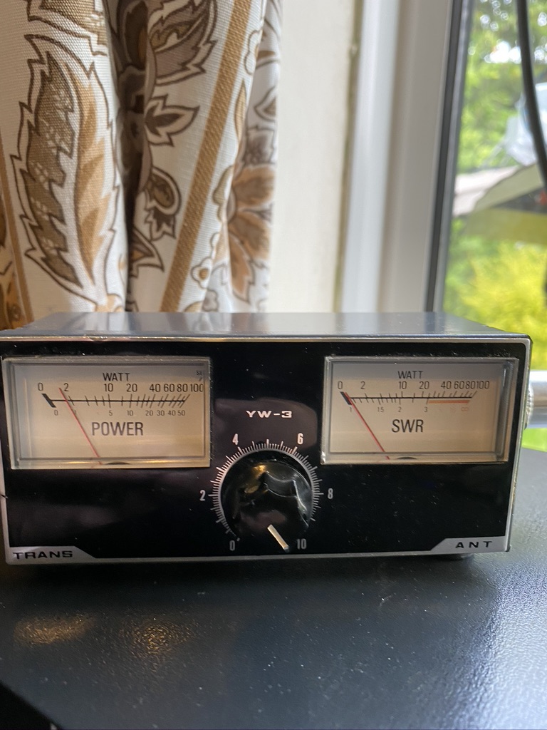
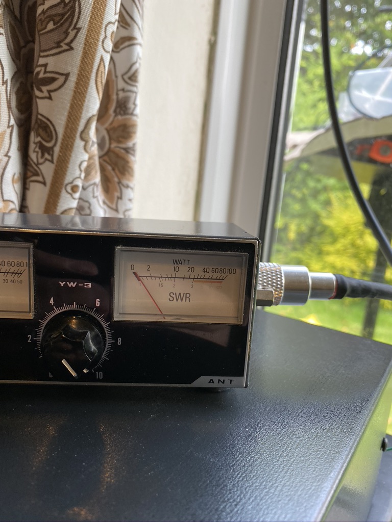
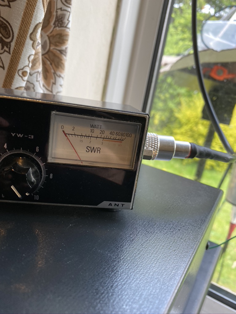
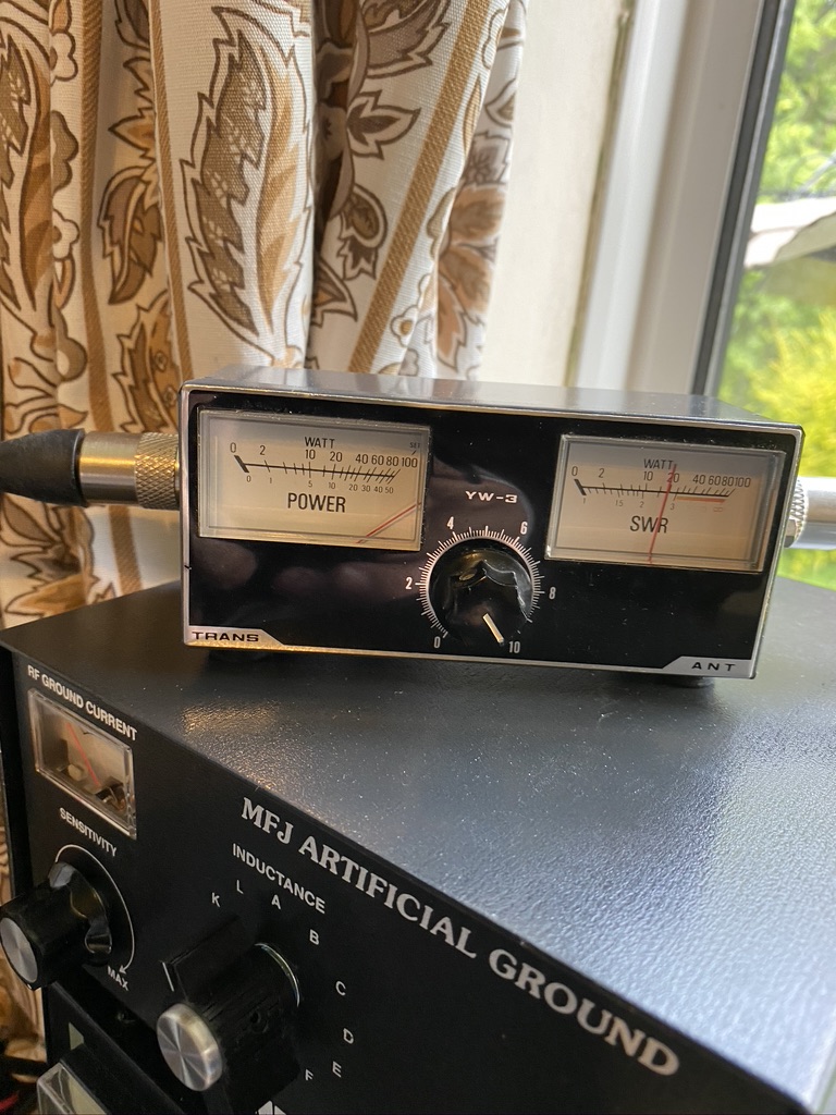
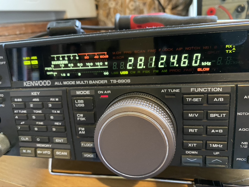
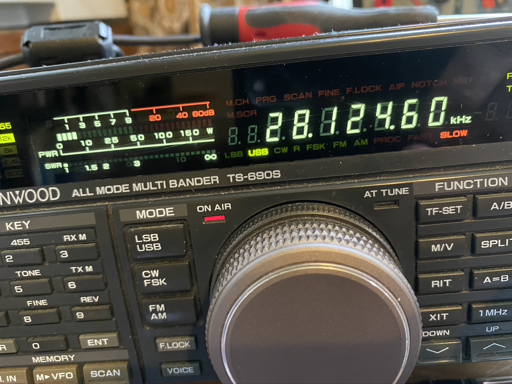
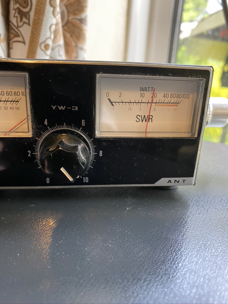
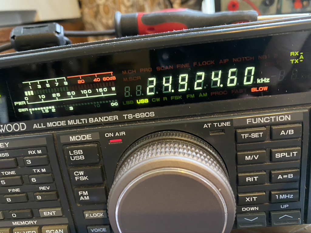
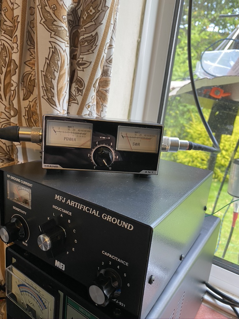
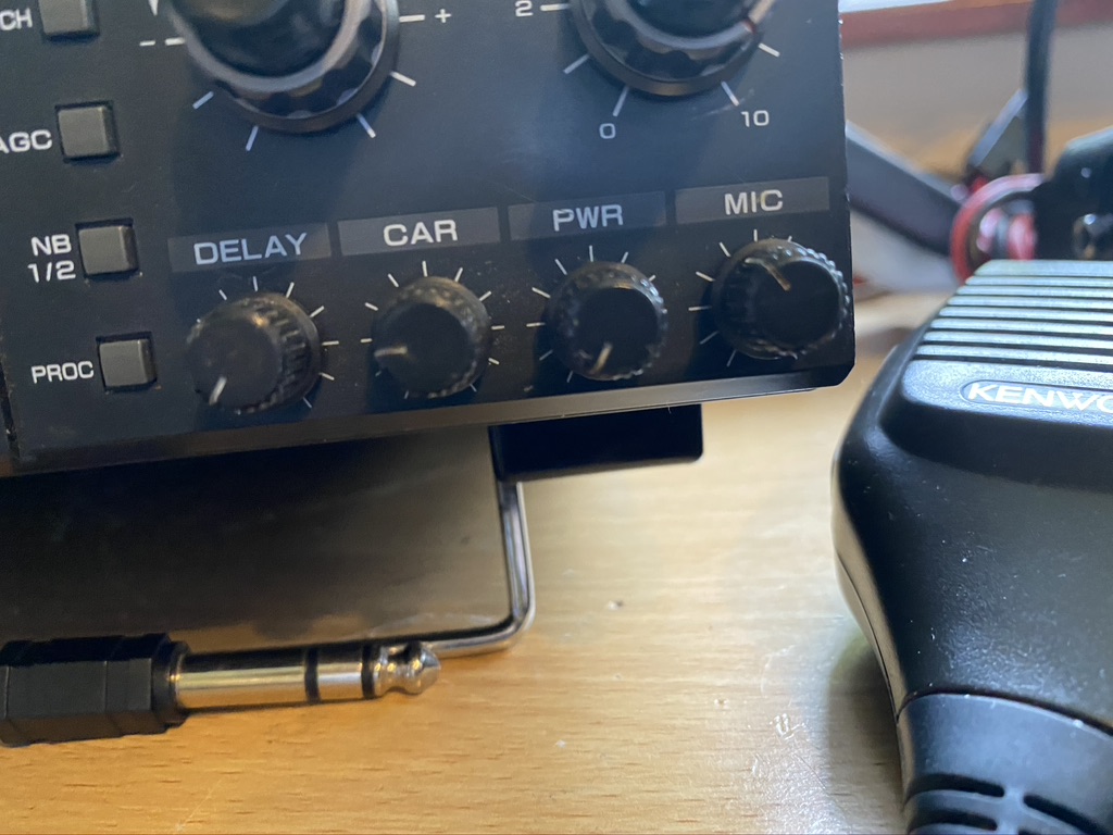
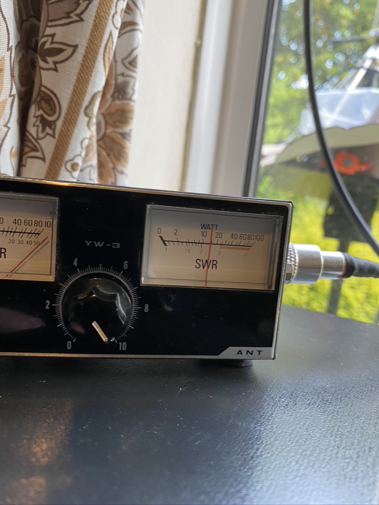
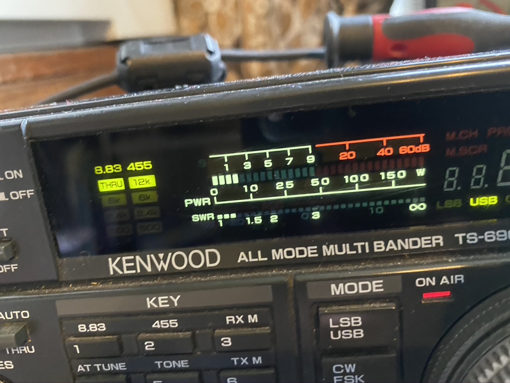
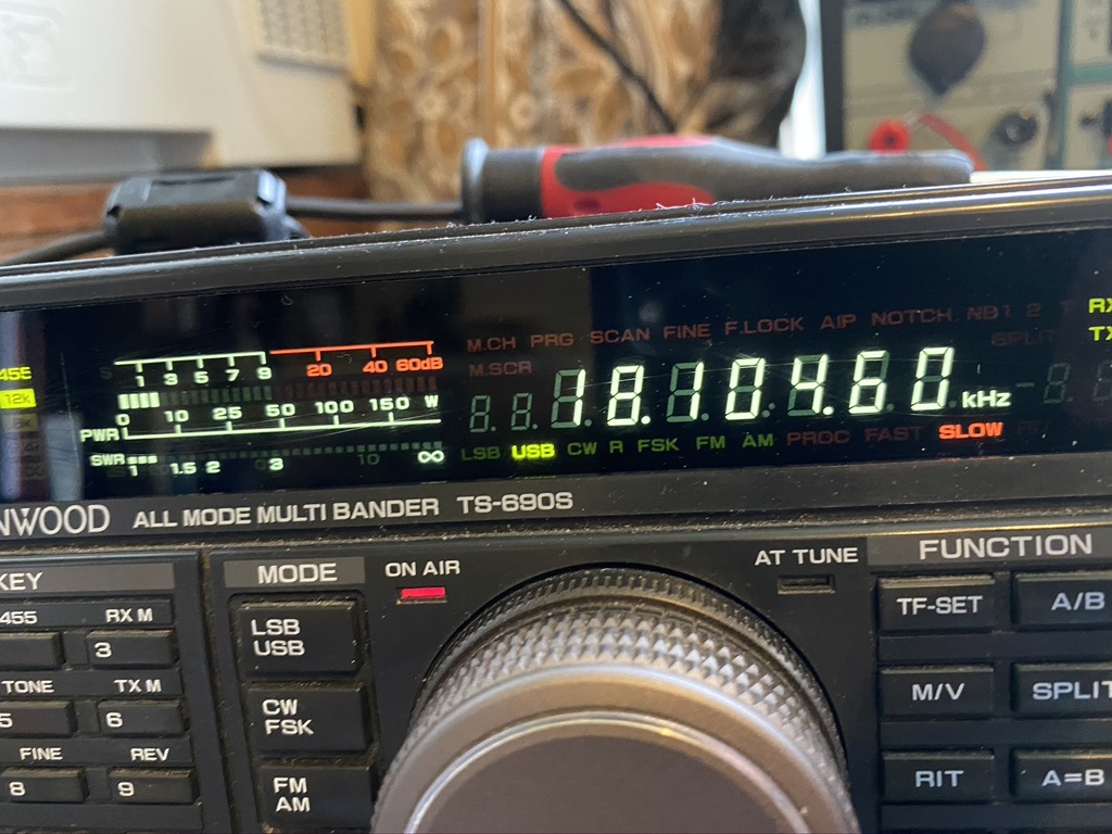
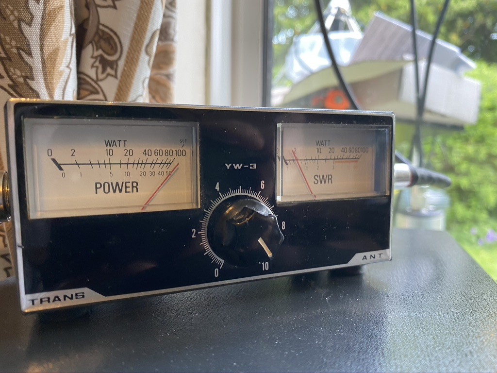
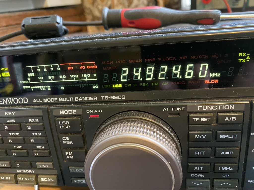
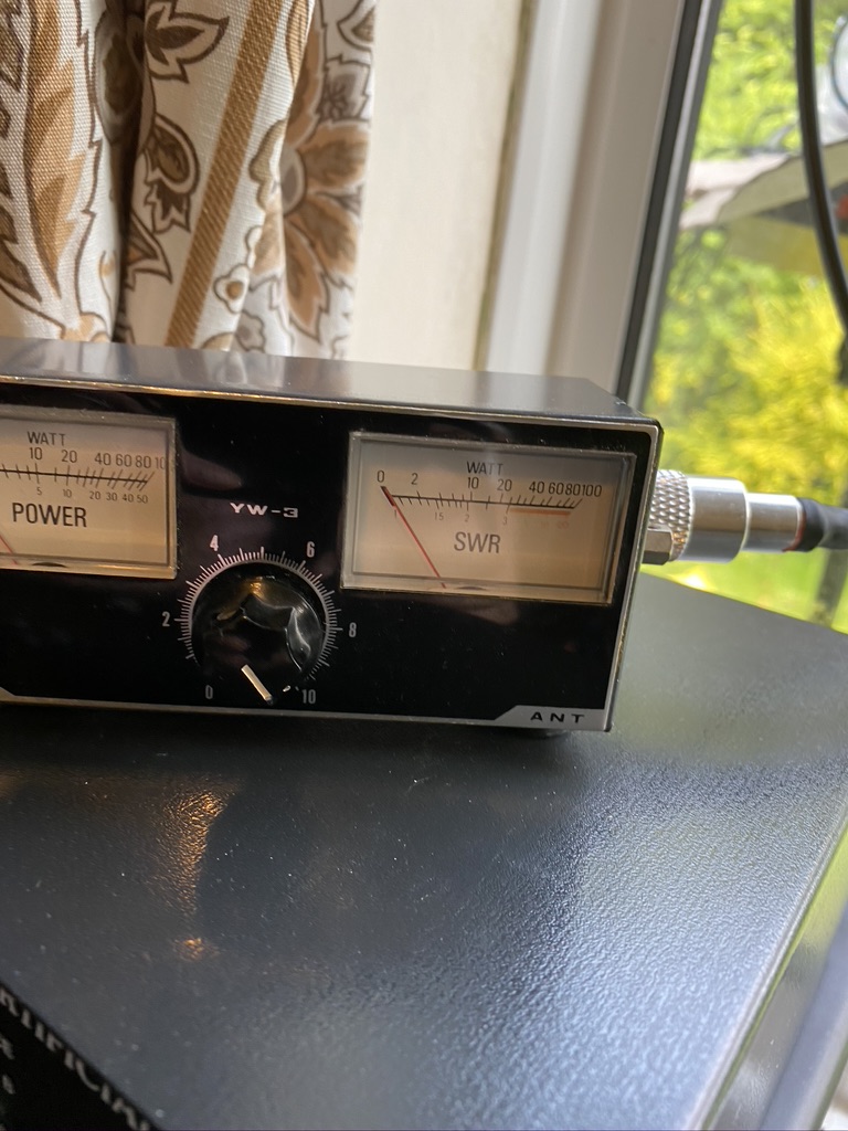
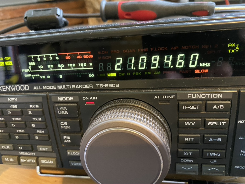
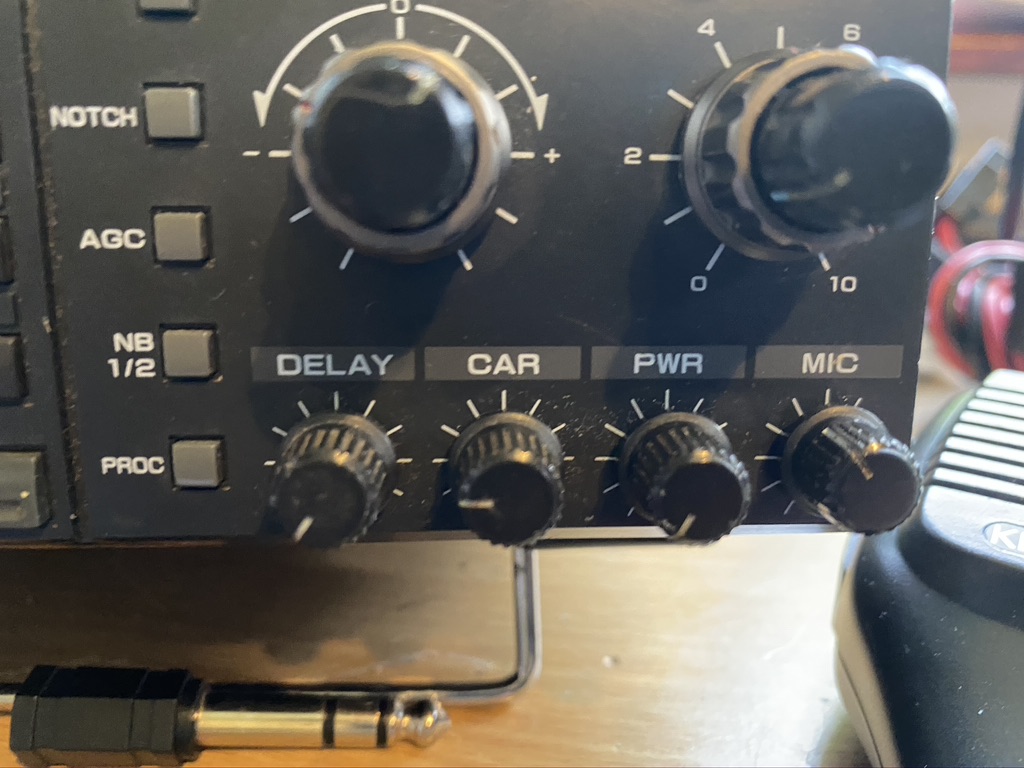
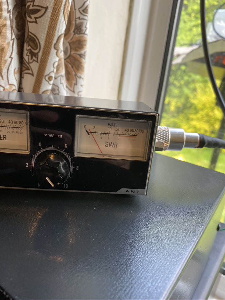
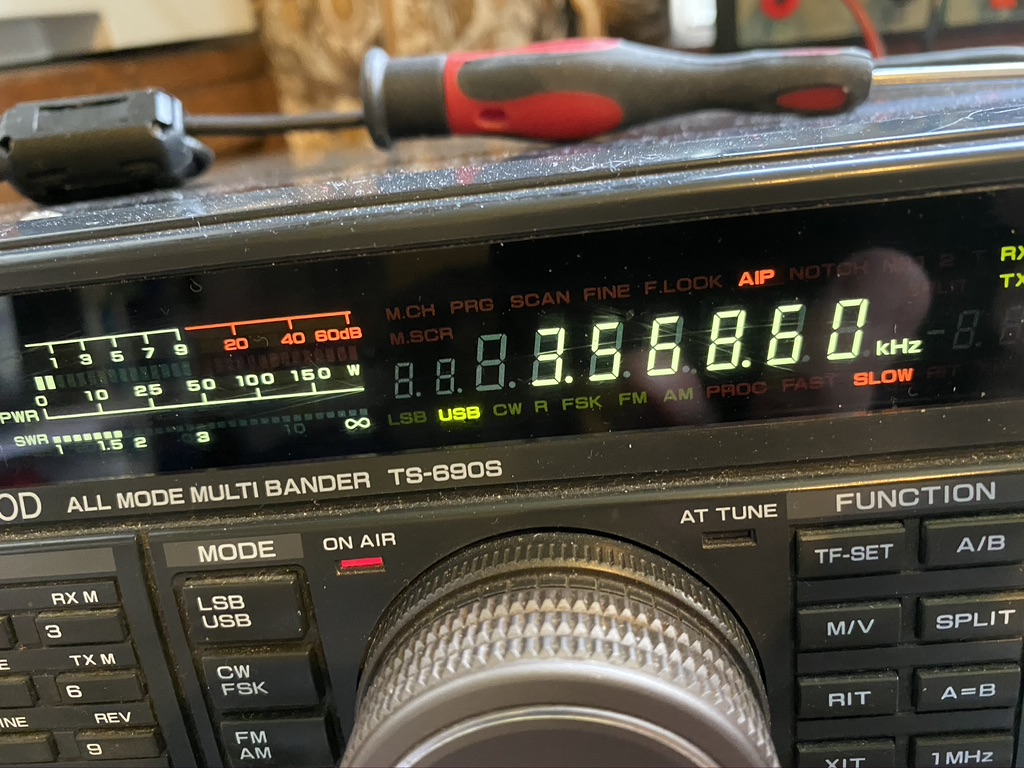
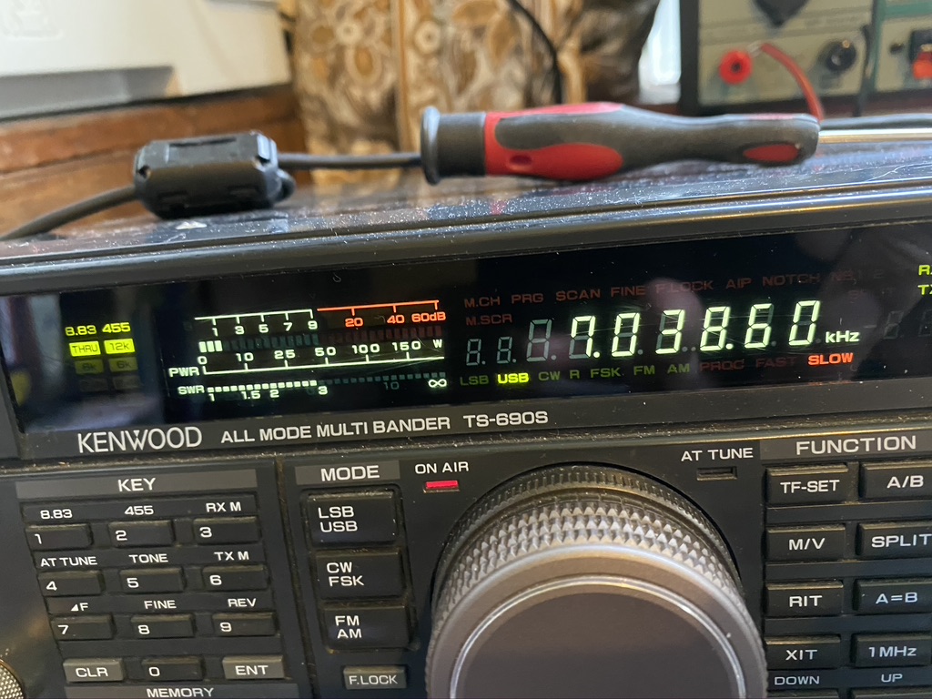
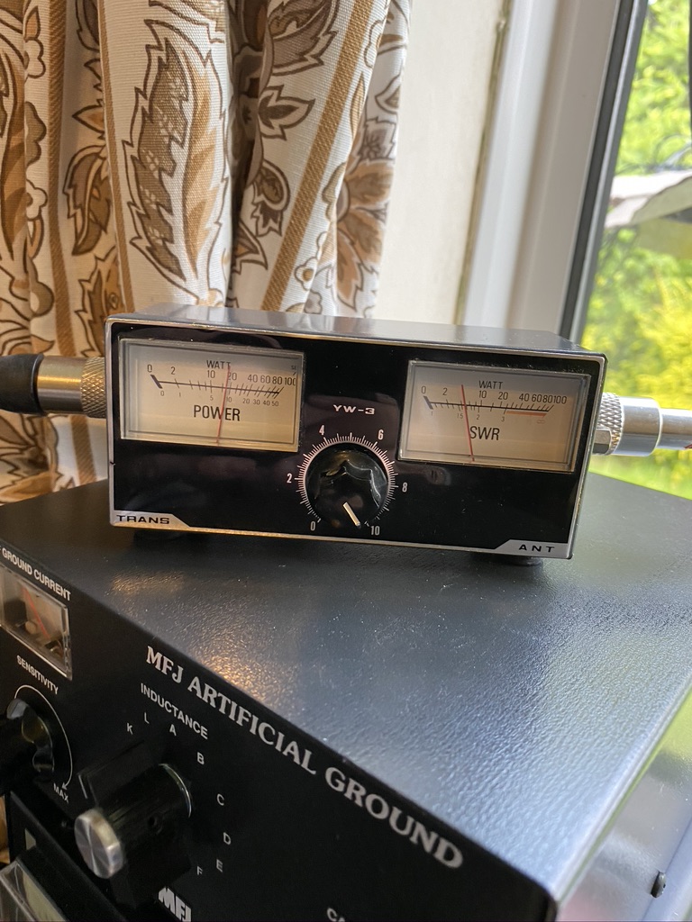
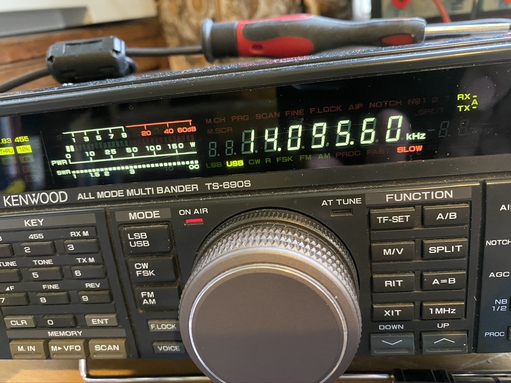
So the next step would be to test. For this i used the two main data modes I currently use, being FT8 and WSPR. I used WSJTX v2.1.2 and finding a ‘gap’ to press the ‘tune’ button. This would give me repeatable results. I am using the TS-690S internal SWR reading and a 2nd hand HF SWR Transceiver (YW-3) for the external readings.
Band
SWR Transceiver
SWR Meter
Notes
10
1.1
1.3
12
2.2
80
17
1.4
1.6
20
OFFSCALE
2.5
RX is very clear 5/9
40
2.2
1.1
80
2.1
1
160
OFFSCALE
To be expected
30
OFFSCALE
80m wire ?
15
1.6
3
Does the VV-3 work at this frequency ?
12
2.1
3
FT8 Testings with new elements on 10+12m and resonant frequencies/others in WSJTx
Band
SWR Transceiver
SWR Meter
Notes
10
1
1.2
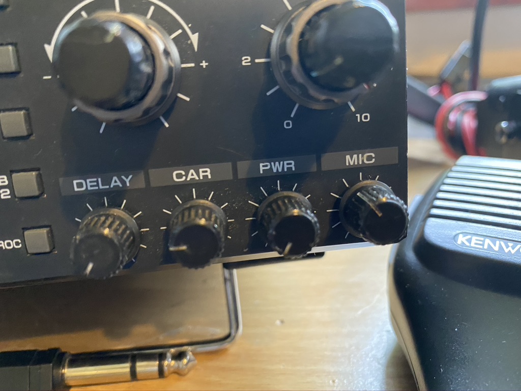
5 Watts is the min setting on the transmit
12
2
2.5
17
1.3
1.3
20
OFFSCALE
40
2.9
1.1
80
1.5
1.1
160
N/A
30
N/A
15
1.4
1.5
12
2
2.1
I am really impressed with the S.W.R. on all the bands, whilst 20M gave a high reading, i suspect that the curve on this band is quite specific. Reception is very strong, so the wire is doing its job in selecting the fequency nicely.
Whilst I wasnt expecting 160m and 30m to be available, for thorughness and future recording, added them (should of done 6m in hindsight). I was happy to see 15m and 12m resonating nicely with low S.W.Rs on of 1.6 and 2.1 respectively.
I will upload a gallery as there is so much evidiential data to show,so browse thru at your lesuire.