Not sure how many people read this on a regular basis, but needless to say apologies for the absence of updates in recent weeks. I’ve got loads of updates to do, with pictures and videos but my MSc has taken over my life at the moment (outside of work).
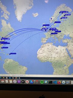
Good news one of my modules on Web Technologies i’ve embraced my course and my hobby and am using WSPR data, amongst others, as one of the components of a website I am building.
Whilst i enjoy a ‘ragchew’ on the IC-705 via D-STAR, the Internet and ‘Bit Encoding Rate’ (BER) has more to do with the quality of the received signal than an actual radio wave. (I use a Pi-Star hot-spot as there is no DSTAR repeater nearby IO90).
With that I know that the IC-7300 is a very capable radio on its own, but even with previous antennas having access to all bands did I ‘try’ telephony that much, preferring to stick to digital communications via the computer. I thought it was time to give it a try and get used to operating telephony on the IC-7300.
The inspiring video section !
I checked out this video and it gave very good examples of setting up the audio for various transmit types. If you have a 7300 it well worth the watch and I’m sure the same principals apply to other radios.
Setup the 7300 for optimal audio
Tim, G5TM, has a great video on calling CQ. Having watched the video I was up for trying calling CQ on the 40 meter dipole I am currently using !
G5TM with great advice on calling CQ
I started calling CQ not expecting any replies, but amazingly on 50W on a dipole I did ! My first QSO on 40m was with IZ6TGS. He was obivously a really experienced operator and it was amazing to reach him ! I was immeadilty drawn to how unprepared I was to ‘log’ – when doing FT8, its so well setup it make it easy. Suddenly I was trying write down the call sign and any other details. Thankfully Adrio was a patient and great operator, we managed to give a report each way and I had made my first HF SSB contact !
It did really show I needed some ‘help’ with logging and operating. Having seen both M0MCX and G5TM operate live on air (its great watching a live stream!) they use a free piece of software called N1MM Logger. You can see them both as they start the QSO they are typing in the call sign and any details they can garner. My problem was that I was restricted to the hand-microphone and my Windows PC neither has a screen or keyboard attached as I connect via Remote Desktop Protocol (RDP). Whilst having recently tided my shack-tables up, there is still limited space on my 7300 table.
I was able to come up with the following solution !
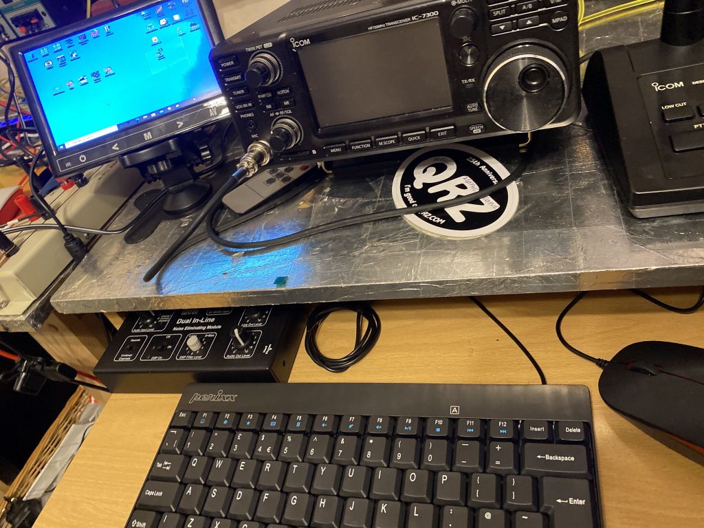
micro keyboard and microscreen
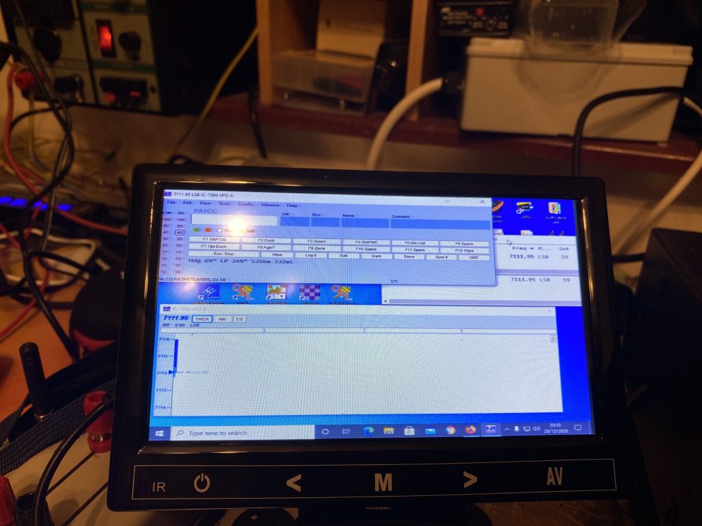
small but clear
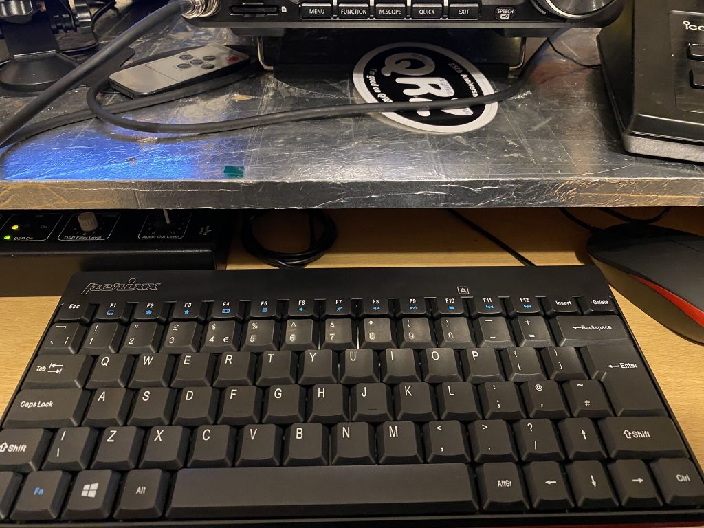
a great keyboard
i can type as I QSO
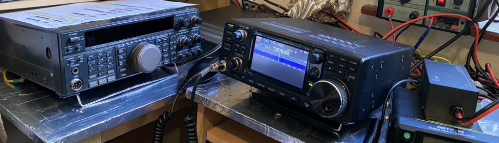
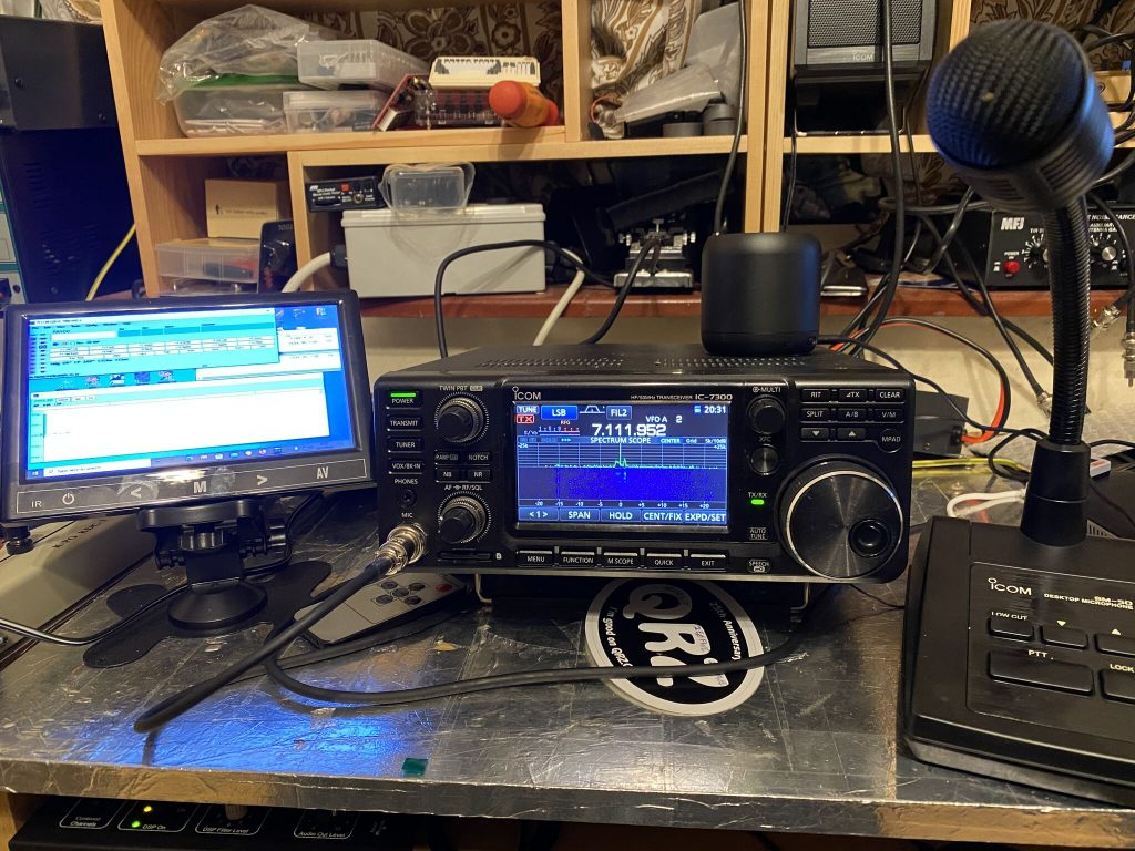
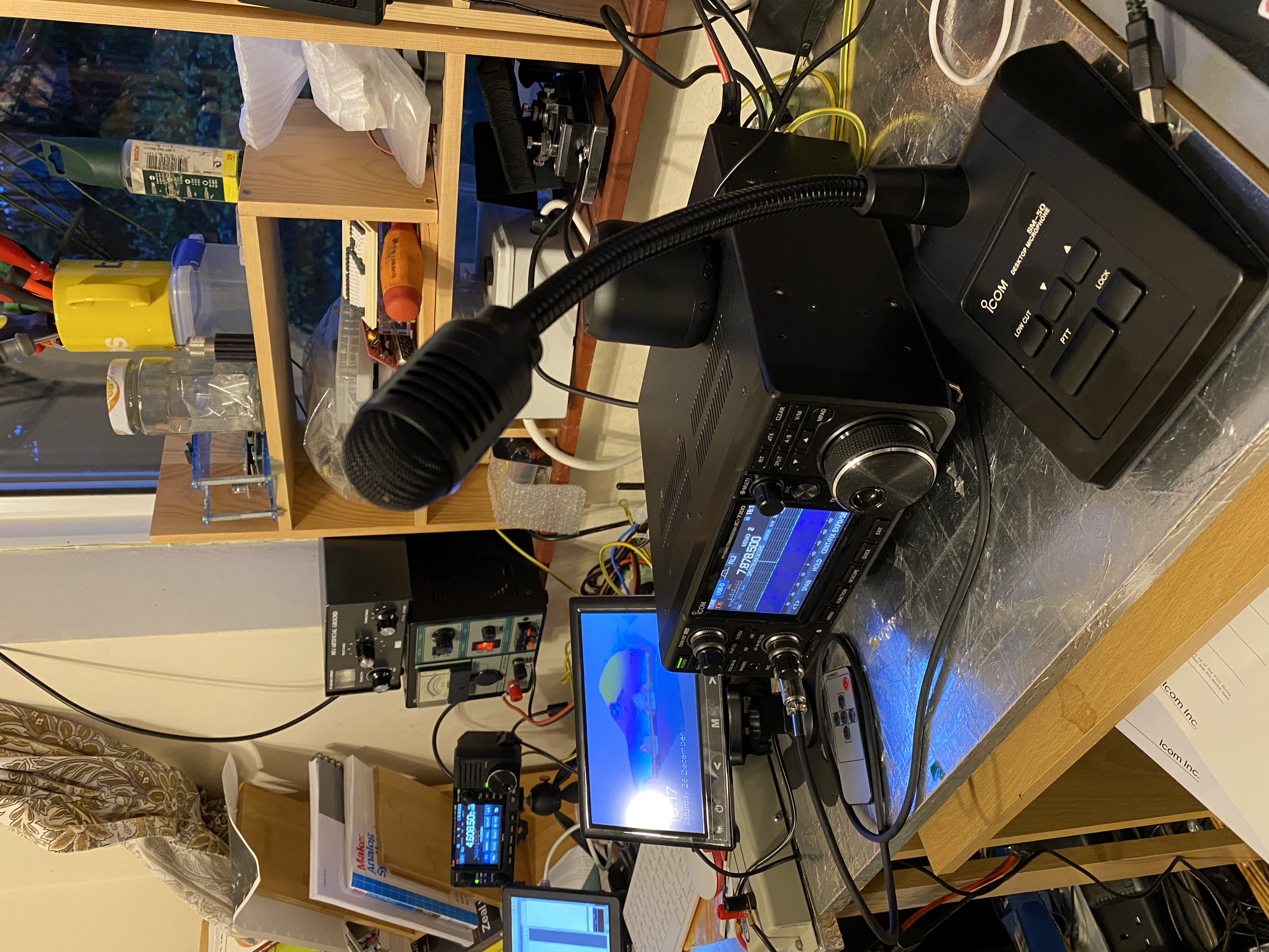
A fantastic setup for both digital and telephony modes
Keyboard and Screen Technology
They keyboard and mouse come as a set from Amazon, the Perixx PERIDUO-212 Wired Mini Keyboard fits nicely on the keyboard shelf under the 7300, along side the BHI Dual In-Line Filter. For £16.99 this was a really good piece of kit, obviousy its not as good as the keyboard i use on my mac, but then i’m mostly using it for typing out call signs and reports, not developing stuff 🙂
I combined this with the 7 Inch Small HDMI Monitor with VGA which cost £36.99. Even at 7 inches and a respectable 1024×600 resolution, I could easily see NIMM with no problem when using my radio. It fits very nicely on the desk and comes with a fairly decent stand. I’ve not even had to fix it to the table and its staying up nicely.
SM-50
The last part of the equation, is no doubt, the most important. Whilst having a QSO i struggled to write down the call sign as my hand had a handmic in it. Whilst there are many microphones out there, the SM-50 is the recommended microphone within the 7300 manual and importantly receives very good reviews on eham. It is not a cheap microphone, nor is it expensive, as my son can attest in his experience of sound engineering, microphones can get *Very* expensive depending on what you want to record and where.
I orderd the SM-50, i was very impressed with how sturdy the base and the flexability of the neck. I could bend this perfectly over to me a few inches from my mouth to make operating alot easier.
The SM-50 is a fantastic microphone for the 7300
I went about setting the 7300 following the videos above and adjusting the microphone gain on the underside of the SM-50 to match the 7300. I also read the manual on how to setup recording my ‘best’ voice for 7300 so i could replay my CQ call.
This also made listening via Wesbree WEBSDR very easy and amazingly i could hear myself ! During this time my CQ call on repeat was picked up by DK4EI. We had a great QSO, his setup amazing, but i was happy with 50W and a dipole to come thru with a 5/9 report into Germany!
Conclusion
If you have been on ‘digital modes’ during the solar minimum, and also maybe slightly nervous of going on HF, i can say its worth putting the effort in to get onto SSB/Telephony.
My key points are
As per Tim’s video sound enthusiastic/engaging – I took my time and made a ‘good’ recording/playback feature of the 7300 – it works !
Set up your audio/microphone well and for the audience/conditions, the pileup busting video is really good for this. I’ve not had to change my settings, and i get great audio reports
Get your logging software, or pen/pad easily to hand, fill in details as you go, it makes the QSO more rewarding and you can spot people again !
Get a good microphone, for me the SM-50 suited *my* needs and had good reviews. You may want a different type of microphone and use it in a different way (VOX/PTT/Foot PTT, up/down buttons, on a bracket.. SO MANY FACTORS).
I am getting (braver?) better at HF QSOs and am currently limited to 40 meters, so you might hear me put the shout out during the evenings and night. Until then I really hope to have a QSO with you !
Having got the 705 which is DSTAR capable spent the afternoon/evening with getting this setup. I already had the components, it was a question of getting it all together !
Register your callsign with DSTAR!
To be able to use the reflectors on the DSTAR network, you need to register your ID. This took only a few hours, so if your waiting on your MMDVM, do this now and you’ll hit the ground running when both your registration and MMDVM arrive!
Register here, you will need your email, callsign and dont forget your password !
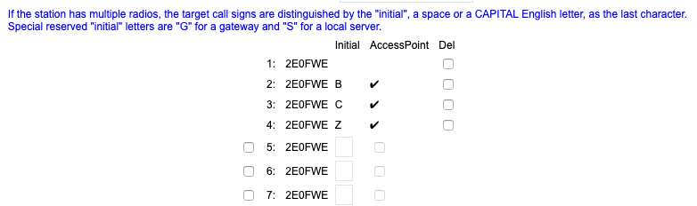
Once your registration is acknowledge you can then setup your gateways. You should add the ‘Z’ prefix, as this ensures the account will stay open (any left without modification for 2 weeks will be expired).
Add B and C for UHF and VHF frequencies to your callsign (which will be automatically populated)
Dstar personal information page completed
This will take time to propagate across the DSTAR network. For DSTAR Administration this is all I had to do to allow my hotspot to attach to the DSTAR network.
PI-STAR
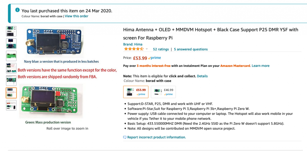
The MMDVM being used is a popular one available from Amazon. This comes as a kit to assemble and includes all the necessary parts to get up and running – although I would recommend getting a dedicated power supply rather than depending on just USB ampage
MMDVM Hotpsot used from Amazon
70cm Antenna using Buddipole
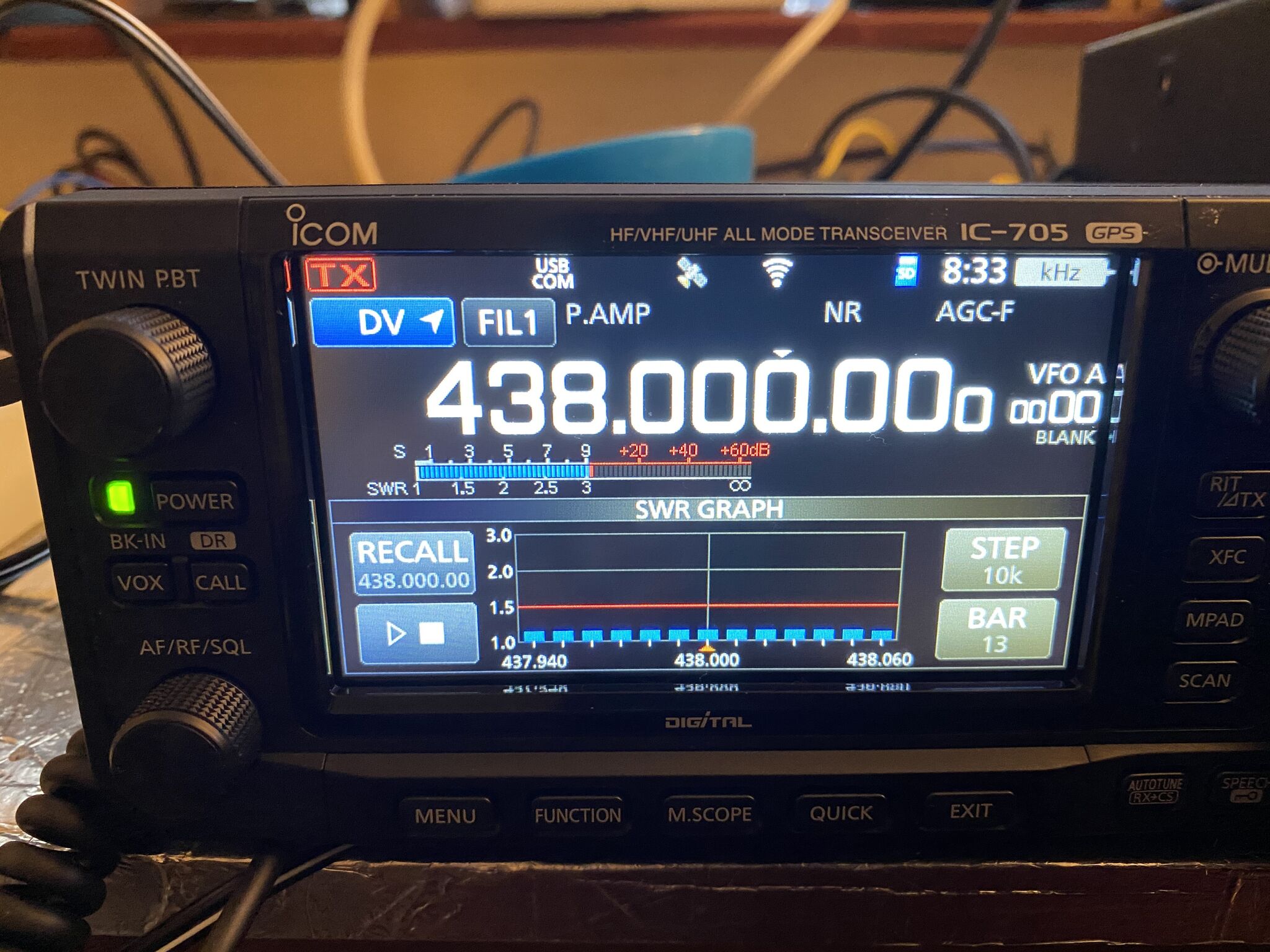
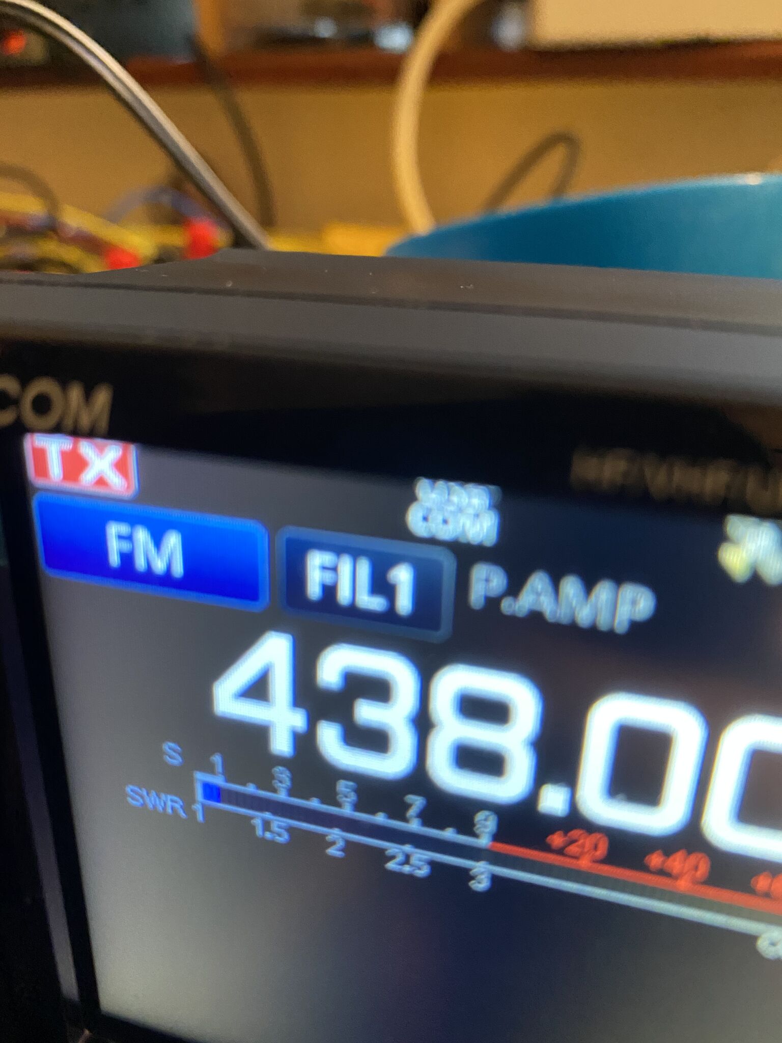
I do have an external 2m/70cm antenna attached to a mast but was unable to get that to work (although later checks via SDR proved it was ok, will detract from the thread). I setup first in 2M configuration then ‘played’ with various lengths to get the VSWR down to 1.1. I used the IC705 internal SWR analyzer.
2M JPole from buddipole – adapted to 70cm
Lengths used and respective colours –
frequency
black
red
2m
14.62″
43.75
70cm
67″
32″
Buddipole antenna lengths
VSWR Sweep on 70cmSWR on 70cm
Configure the IC-705 via Software
I used the IC-705 configuration software on Windows to be able to recreate the configuration steps. I’d advise you to first download your current configuration and save it to ensure you can recover to your pre DSTAR config.
The software is available to download from here – its a simple Windows Instal. The USB cable interface on the IC-705 is located just under the power cable.
This is the full video on how to configure, but snippets of the essentials are shown below.
Configure Icom radio for DSTAR
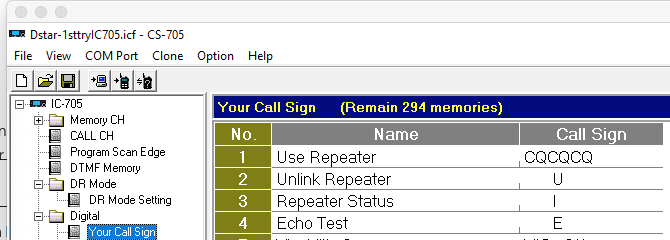
Once loaded, the essential configuration is the Digital/My Callsign. Although its called ‘your call sign’ it contains anything but (for this configuration). Add in the following table
No
Name
Call Sign
1
Use Repeater
CQCQCQ
2
Unlink Repeater
U
3
Repeater Status
I
4
Echo Test
E
Essential ‘your call sign’ entry. 7 Spaces for 2/3/4 then the character.
All, apart from CQ, DSTAR commands are 8 Characters long, so where you see the white-space these are created by 7 spaces, then the character, i.e. for Echo Test <SPACE><SPACE><SPACE><SPACE><SPACE><SPACE><SPACE>E
these are the messages you will send to the hotspot
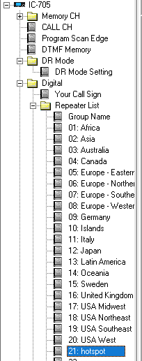
You will then need to configure the radio for the new pistar hotspot
I created a new group called ‘hotspot’
Add Hotspot Group to the Repeater List
I then added the configuration for the hotspot to match the DSTAR configuration and the frequency of the radio (obtained from Amazon page – in this case, 433.550.000)
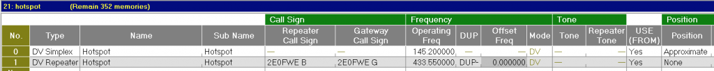
Configure the hotspot
You don’t need all the entries, the signifiant ones are as follows
Number
Type
Name
Subname
Repeater Call Sign
Gateway Call Sign
Operating Freq
DUPt
Mode
1
DV
Hostpot
Hotspot
2E0FWE B
2E0FWE G
433.550.000
DUP-
DV
Settings for my call sign and MMDVM
I then pushed the configuration to the radio and rebooted. This completes the IC-705 Configuration.
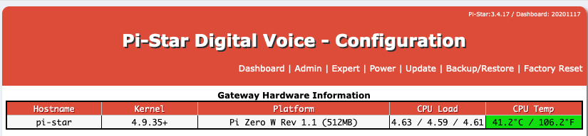
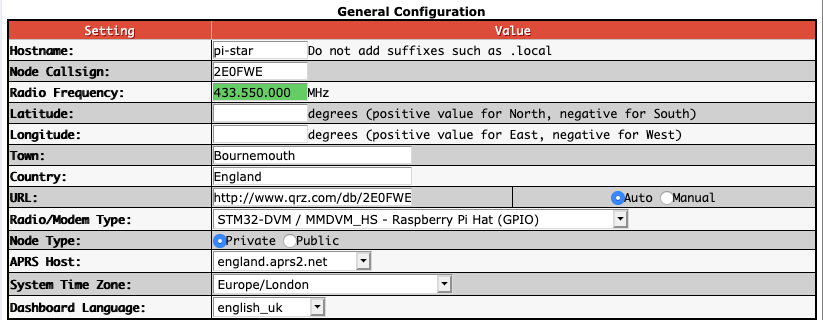
Pistar Configuration
The next step is to configure the Pistar for DSTAR. If you havent configured your PI for Wifi yet, you’ll need to do that first. Probably the easiest way is to use the PiStar configuration tool, but that means sending your Wifi username and password, which some may not like, alternatly I connected a keyboard and screen with configuration on the commande line.
Once reachable on wifi, you will be able to reach the pi-star administration pages. Most routers running DHCP will allocate a record in the .local’ domain, so simply htttp://pistar.local/ will get you to the portal, default logins are username pistar and password raspberry. I suggest changing this on the admin page right away.
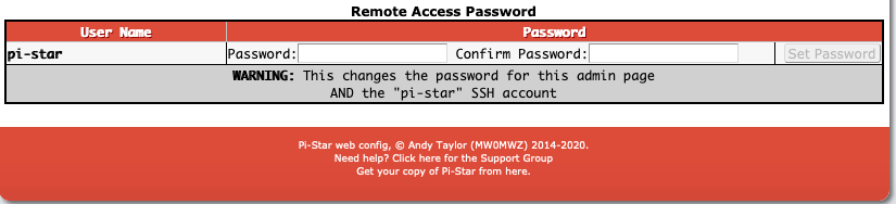
Navigate to ‘Admin’the password is the very bottom of the page
Restart the pistar and login with the new password.
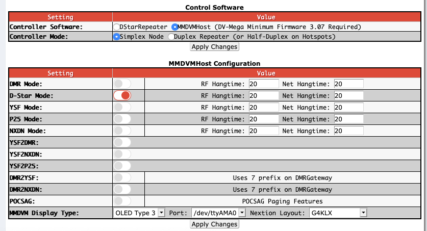
First configure to use DSTAR. from the panel. For now, keep it at DSTAR only.
Settings #1
If you make any changes, you must click on Apply Changes for *each section* else your changes will be lost.
Settings 2
The essential part here is to get the radio frequency and call sign correctly, i.e. 433.550.000 for frequency and your own call sign in place of 2E0FWE. I’ve removed my exact Long/Lat, but you can put your own in. Once complete, click apply changes. I believe in the UK we are required to put ‘Mode Type’ to Private as we cannot ‘broadcast’ as amateur radio users in the UK (which I think ‘public’ effectively does)
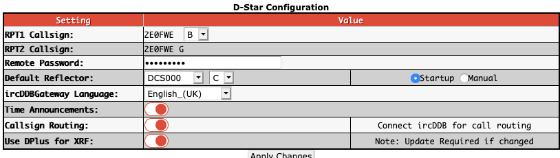
Settings 3
Here we match our hotspot config with the DSTAR network. As the node is on 433Mhz, Channel ‘B’ is the one to use, if it was 144Mhz, then C. Hit apply and that wil complete your configuration !
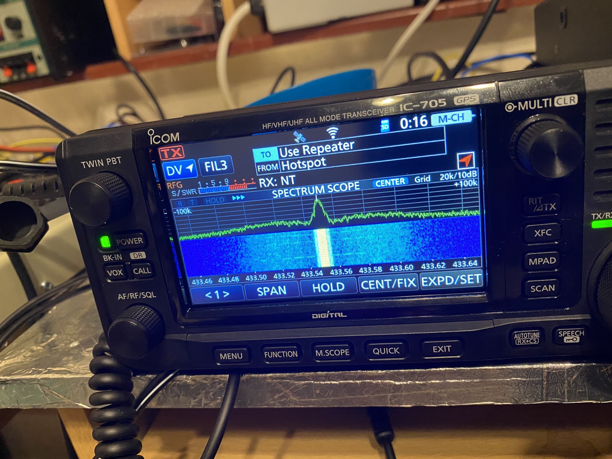
IC-705 Usage
With the DSTAR Registration, PiStar and IC-705 Configuration complete, its now time to enjoy using the IC-705 on DSTAR via your own hotspot !
DV Mode
PRess the CALL button situated on the left side of the radio and change from FM to DV. To use the hotspot tap ‘from’ on the screen, select ‘repeater list’, ‘hotspot’ then the hotpot added via the configuraiton tool, in my case 2E0FWEB.
To start using right away, tap ‘to’, select ‘your call sign’ and ‘use repeater’. You should now be able to key-up and call CQ on DSTAR ! Of course you can test using Local Echo and Status commands (just adjust the last step in ‘yor call sign’.
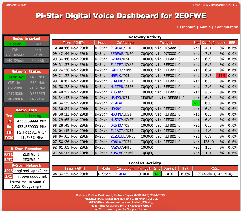
You will be able to confirm your radio is communicating with your hotspot and the DSTAR Network.
Local RF Activity shows our radio is speaking to the hotspot, gateway activity shows others in the talkgroup talking
The DSTAR ‘last heard‘ feature can then confirm you are on the DSTAR network.
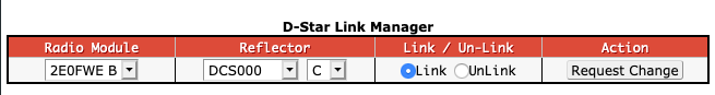
Finding talk groups / repeaters,etc.
With your IC-705 now on DSTAR you can choose which Talk Groups and Nets to join. There is an extensive list available on here. You can configure the group via the Pistar admin page and putting or selecting the reflector.
choose your reflector!
I hope this helps people use the IC-705 on DStar, it took me a little while to piece together all the pieces (including the antenna !) to get it working, but is worth the effort. There seems to be an increase in simplex D-Star usage on HF with the IC-705 being able to do the full range of HF, VHF and UHF.
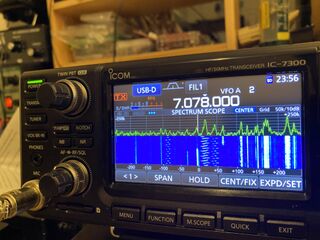
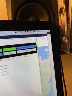
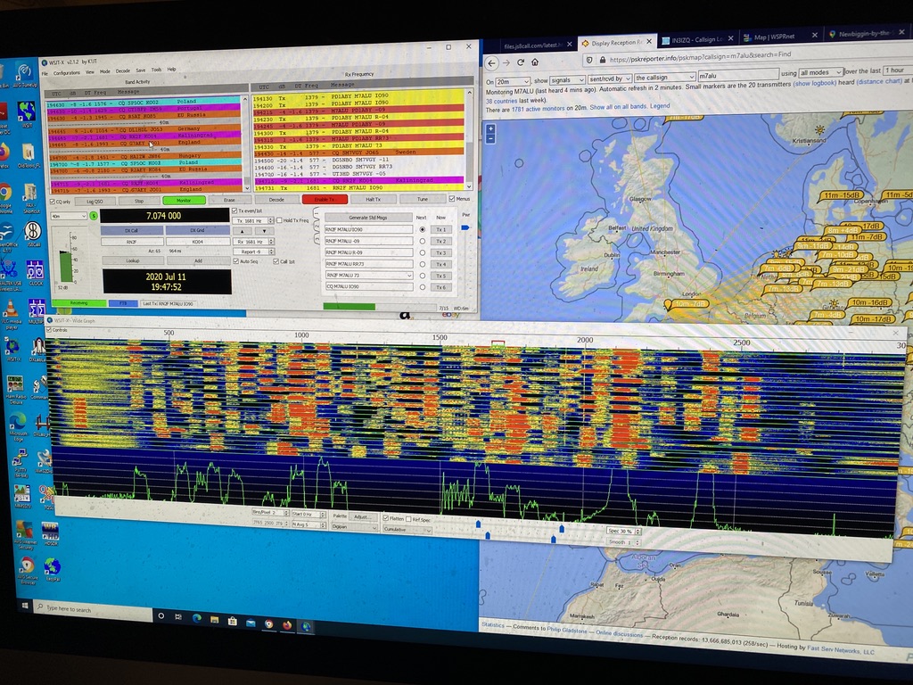
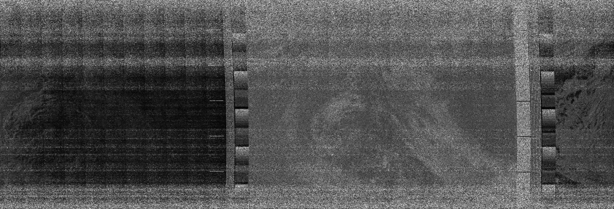
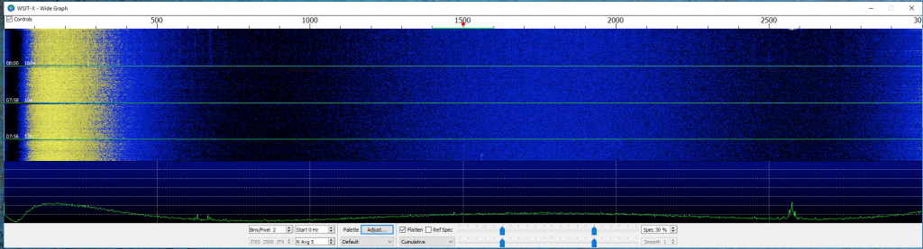
Whilst enjoying my studies of Machine Learning I had the radio on in the background. I was very interested to see some ‘patterns’ on the 40m band
Interesting patterns in the waterfall
Not right at this time, but earlier in the day my fellow ‘neighbour’ ham G7VRD told me these are OTH. What is that ? Well this is Over the Horizon Radar, where radio signals are based off the ionosphere and then measured. They have been around a while, as in the 1950s, but technology has ‘evolved’ and ‘new’ arrays are being built ! These patterns were throughout the 40m band most of the evening ! Whilst annoying if you wanted to use the band for its intended use, nevertheless provided some interesting reading on what OTH was and how it worked.
FT8 and JS8 Call
Whilst I was busy with Juypter Notebooks, and as I now have the antennas plugged in thought it interesting to monitor JS8. Its nearby digital mode of FT8 gets plenty of traffic, JS8 is very sparse, which seems a shame as it looks a good way to ‘chat’ via FT8 digital mode.
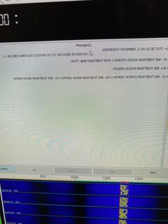
I sent out HB and ACK’s and it was clear there are people listening, but not many sending CQ, nethertheless it was an interesting evening and this somewhat ‘dubious’ amateur transmission was observed, whilst interesting am wondering the legitimiacy of it.
Covid Stats transmitted into JS8 Call (no call signs only a reference of the source material)
I enjoyed seeing JS8 Call in operation though and didnt interrupt my studies, so i could do a bit of both.
late into the night… that’s data science for you and having a day job
So i enjoyed my FT8 and Data Science, having worked thru the night and with work-work the next day headed for bed eventually at 4AM.. 🙂
As i have been doing more ‘re-arranging’ in the QTH, I thought I would revisit the snippet from the previous weeks posting on NOAA & METEOR decoding. I have evolved from ‘home brew’ antenna and tools on OS-X to fully automated and a specialist NOAA/METEOR antenna.
Hopefully by the end of the post, you will get a feel and and idea of where you would like to start or explore further !
My first interest in weather and amateur radio came from receving Wefax images. I still do this as it complements and also gives me some idea of interference/reception issues as i can usually clearly see any issues in the fax.
My favourtie charts are the UK ones available from on 4608 Khz trasmitted by Northwood.
<insert pic>
I find the detail and various types of graph really satisfying to read and decode via HF.
Following on, i found on youtube about a simple antenna and using SDR receiver to decode ‘NOAA’ satellites
where it started
The audience here is very clearly windows users, and whilst I have a Windows 10 machine for HF Digital modes, i wanted to keep the SDR seperate from that system.
I built the antenna from bits I had around, although it did take up quite a bit of decent low-loss coax to get it up a reasonable height.
Original home-brew NOAA antenna
Get the antenna orientated well North-South effected the signals the most. Whilst heigh was important, gettign the polarization brought about the best results.
first NOAA decodes via standard SDR, gqrx and
My first reception pics, whilst not amazing, really pleased me as the technology was at least working correctly. On a mac the missing component was being able to decode the ‘wavs’ to images, for this i used https://github.com/artlav/meteor_decoder which was easy enough to build via homebrew.
I monitored https://github.com/csete/gpredict where i could manually and getting the direct overpasses with the V antenna produced very good results.
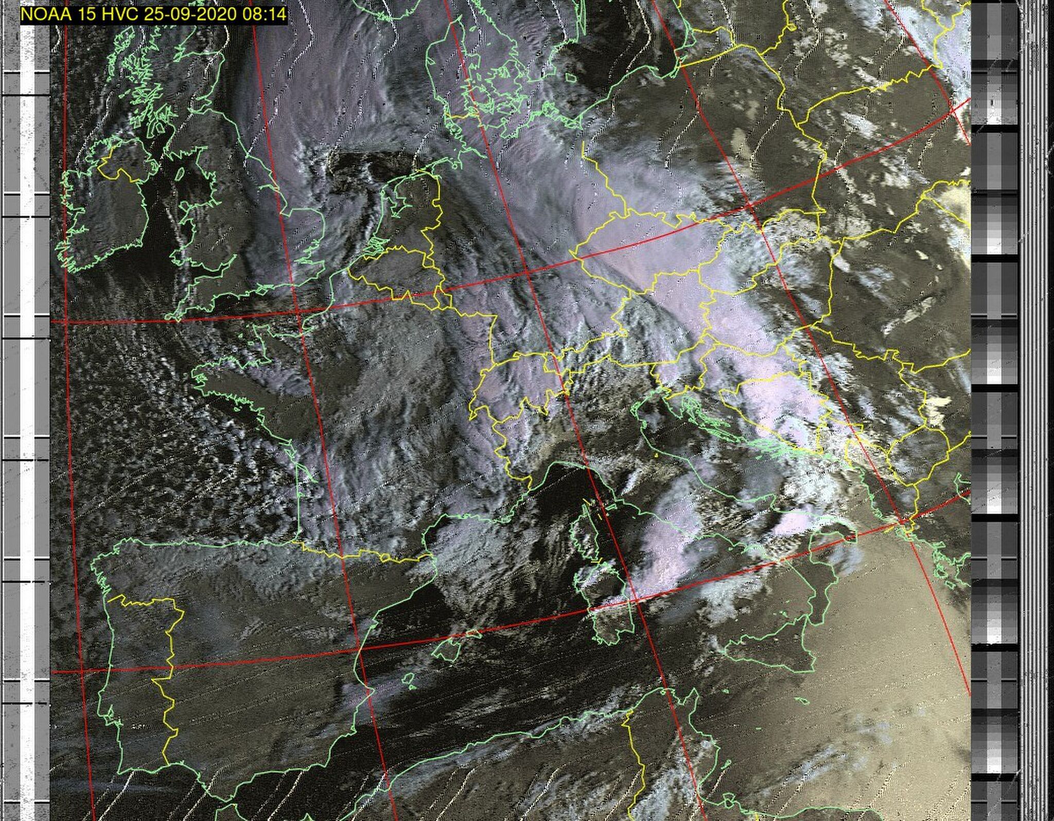
results when following a direct pass over, still some interference, but clearly visible UK and well defined cloud structures
I continued to do this for some weeks and built up my collection of NOAA pictures. I had still yet to sucssfully decode METEOR-2 as that was a digital signal and passing times were not in favour of a day-time working schedule.
We are still currently in a Covid-19 situation as time of writing and since Feburary 2020 here in the UK, so whilst many designs of NOAA antennas exist, I very much avoid supermarkets/large DIY outlets,etc unless absolutely essential, and usually for ‘click and collect; (Order online, pick u pin store, no wandering around).
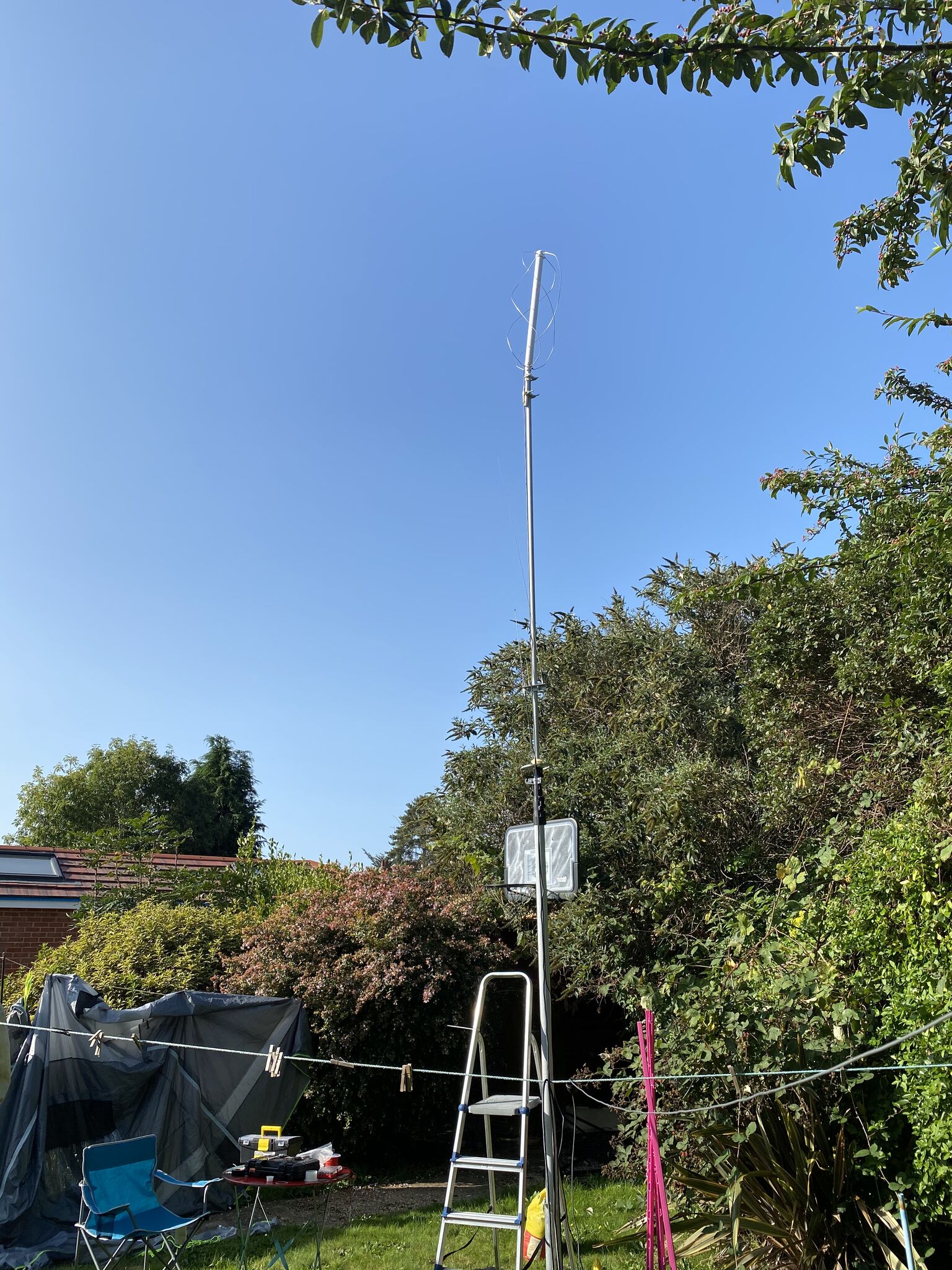
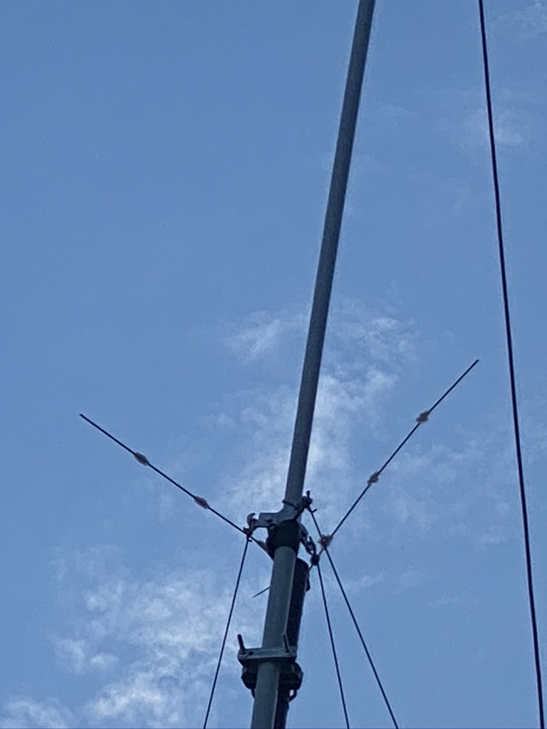
With that in mind i reached out to Dr Google to find pre-made NOAA antennas. This thread on reddit https://www.reddit.com/r/RTLSDR/comments/8biful/is_there_any_place_to_buy_a_decent_137_mhz_noaa/ gave me the link to the National RF antena http://www.nationalrf.com/satellite-tenna.htm. These are built to order, so there is a wait time, but it is well worth it. I was kept fully informed of progress and still had my V antenna to keep me going. Packaging from the US was fantastic, very well protected and assembly was very easy. I did have to get some PVC pipe to use a ‘mount’ to the mast and a BNC to SO39 adaptor, but these are very easy to come by and have no real loss to the to the receive-only antenna.
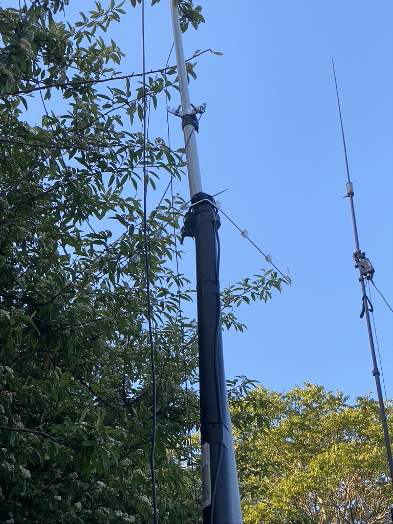
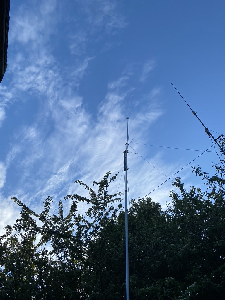
National RF antenna up approx 2.5m
I used my VHF mast, replacing my 2m/70cm antenna with the NOAA antenna. Whilst the mast can go up 30ft, it requires careful observation and maintenance to keep that high. Instead, i opoted for just over roof height of 2m and a clear line of sight to the horizion.
The antenna greatly improved the reception of signals as later pictures show, albeit I am still using the mac and GQRX and a simple SDR at this time.
the helical antenna greatly reduced interference and improved the length of received signals
I continued with the Mac, SDR, GQRX, Gpredict and meteor decode for quite some time, but as i got busier with work i had no time even to manually decode, as much as I enjoyed it !
The next step was to further improve reception and automate. This was accomplished by purchasing filters and amplifiers specifically for the NOAA RCPT frequencys in VHF and then re-cycling a Raspberry PI3.
The original video gives the necessary filters, but for a shortlist here they are
NooElec SAWbird+ NOAA
Flamingo+ FM – Broadcast FM Bandstop Filter v2
NooElec NESDR SMArTee XTR SDR
As I wanted to automate this and provide a simple way to just look at the received images i used https://github.com/reynico/raspberry-noaa repo, which was by far the easiest package to setup and use on my Raspberry pi.
If your not familar with linux/unix this could be a bit of a blocker, as you do need to manually edit some configuration files, so being familary with standard OS commands and a text editor like ‘vi’ i would say are the ‘essentials’ to being able to use this. I dont mind saying i had to refresh my memory on how ‘at’ the scheduling tool worked having always be a ‘cron’ person.
In practice once setup, there is very little to do, but what i have done is to alias ‘atq’ to make the list of tasks in date order.
This makes reading the scans far easier and i can still use gpredict on my mac to see which ones are the most interest to me. The software will automate, and try, every scan, but if rtl_sdre is already running, will not be able to run. In that case its always useful to ‘prune’ out the less interesting or scans which will suffer the greatest interference. I always priortize Meteor passes over NOAA passes as Meteor decodes seem to be. a maximum of 2 per day. This is easily managed by the combination of ‘at -c <job>’ to ensure no duplicate tasks are running.
I have been running on a PI now for just over 2 weeks, and as part of the QTH tidy up am moving the Pi from a ‘desk’ to a shelf where it will be safe and less prone to me knocking the amplifier and notch filter out.
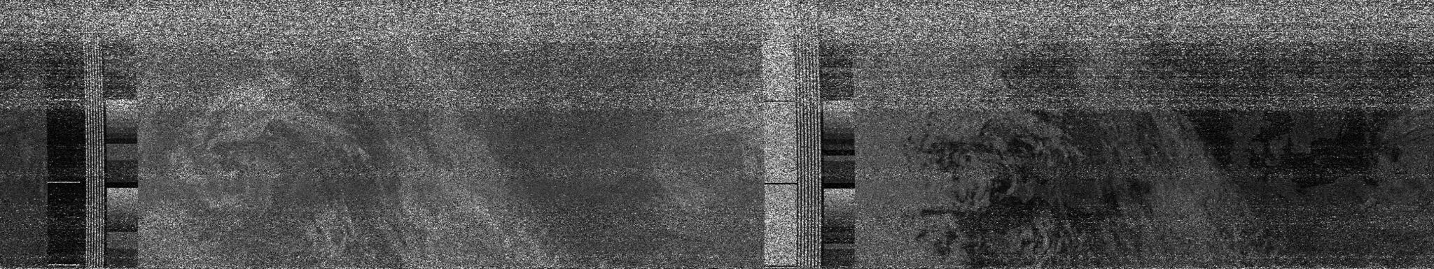
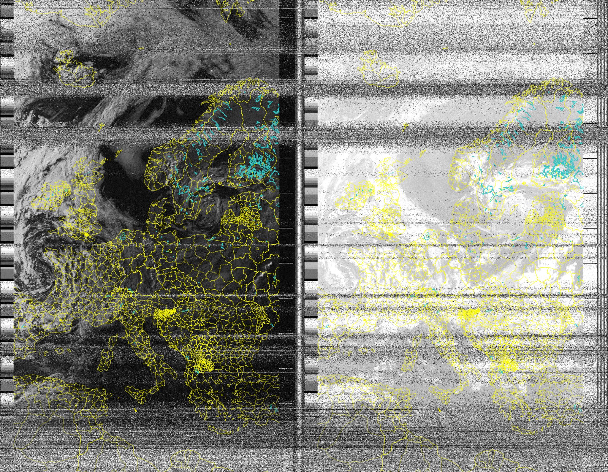
I am amazed by all the scans i can receive and thoroughly enjoy understanding how it works, and being a recipient to the amazing images that both the NOAA and Meteor satellite send for free !
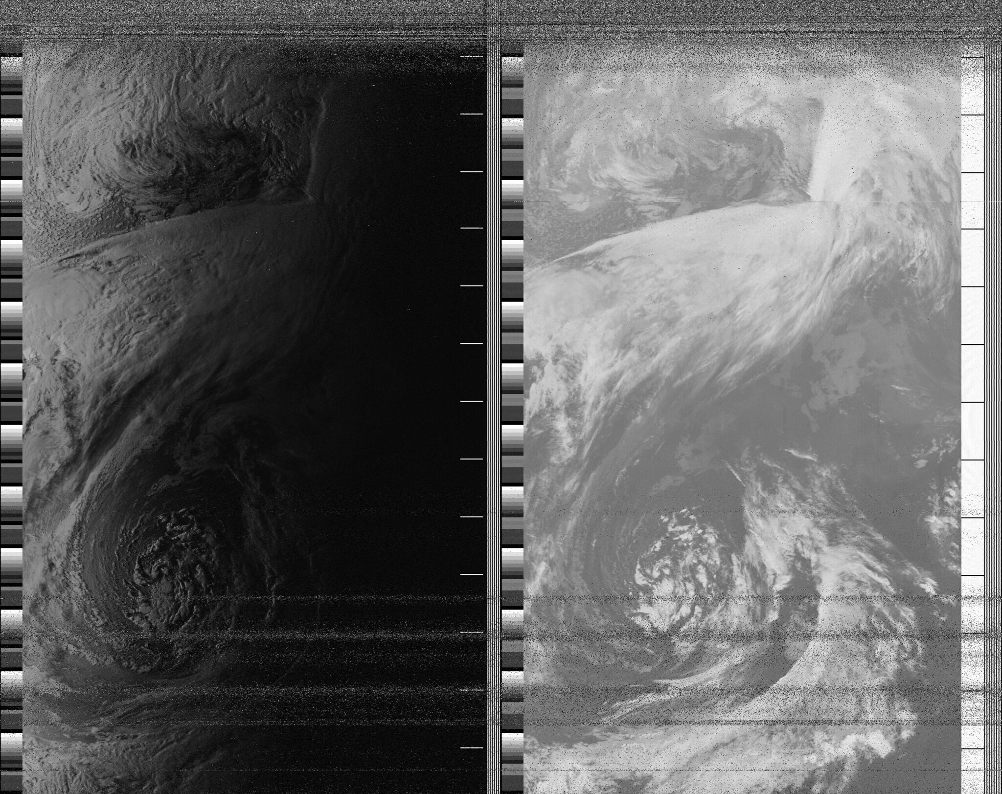
Example NOAA IR via the Linux Raspberry PI setup (some interference due to building work near QTH)Meteor decode – note the interference here is to a digital signal, so rather than static, its loss of pixels in the decode.
Overall i can say that investigating the weather satellites has really complemented by amateur radio activities. I’ve learned how important good antenna design is by the progression from a simple V dipole to a professionally built helical antenna, and the use of amplifiers, band filters and the right SDR unit to use for the hardware available.
I have since purchased 2*Pi4 as I would like to use a Raspberry PI more with the other SDR’s i have (Airspy, HackRF) to learn to program and enjoy the decoding more. Building good antennas will only help what i need for future amateur broadcasts as well.
Overall, i can really strongly recommend decoding weather satellites, if anything you get amazing images of your QTH and combined with WeFAX you can make your own weather predictions !
Have had a great weekend on the radio logging up QSO’s via FT8. I’m now also using LoTW and importing those into QRZ – this has helped with getting more awards. I dont think i will do any more ‘logging’ tho as managing two (and wanting to automate them) is getting enough !
Was really glad that I got another award via QRZ – the grid squared award !
Grid2 accomplished !
For the non amateur radio users what this means is that the globe is segmented into ‘grid locations’, the reference codes being ‘maidenhead locators’ – for this award there has to be 100 unique and confirmed grids. Was very happy to get this done on my foundation licence.
Also was very lucky and got a QSO in the Canary Islands – which is officially classified as being in Africa, which means I’m now only one continent away from the continents of the world award !
Whilst i have heard south america, i’ve never yet managed a confirmed QSO – so it will be quite a challenge but hopefully with the summer hear propergation will improve and i can make that QSO !
Its been a lovely warm weekend down in Dorset, and that seems to have affected the propagation. I had a great time on FT8 and JS8 Call, reaching amazing distances and really good signals being put out and received. I had many logged contacts and good signal reports.
40m got *busy*
By the evening 40M got as busy as I have *ever* seen it, as shown in the picture above i switched about the bands and was making contacts on 15M as well, it was the best conditions I had seen so far !
Resume work on the Kanga Kit !
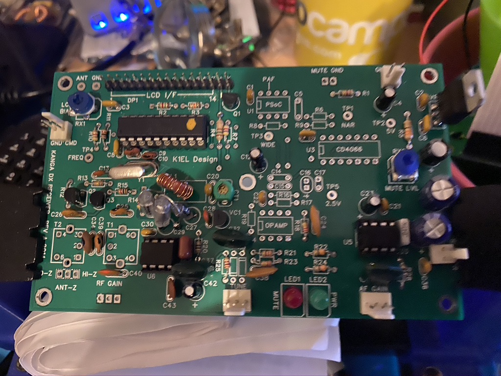
After a break of sometime, I have resumed work on my Kanga Kit – this fits in with the news I’m putting below, but I have a big thanks to John Clements who helped me fix a fault with the kit I was unable to locate. John found the issue (soldered pin-header together – hidden by the plastic) and returned the now working Kanga kit to me ! I have resumed work and am taking my time – I’ve completed more work on the resistors and capacitors on the Active BPF.
kanga kit with added capacitors for BPF stage
I’m taking my time, esp as the board is now quite ‘busy’ – the next step is to add diodes and IC’s. Its really close to completing the build, but taking my time to ensure no more mistakes !
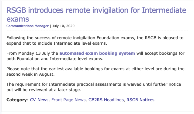
RSGB Announce Intermediate Exams on-line !
As shown in the picture above from the RSGB site Intermediate exams will be available from the 13th ! (in 8 minutes time as of writing) i’m very excited that i will be able to book my exam and get use more wattage but also gain more insight to a very interesting hobby as I continue my amateur radio development.
Whilst the practial assessment is waived currently, i will continue to build my Kanga Kit, so if the issue did come up of what Kit I did build, this is well recorded and documented.
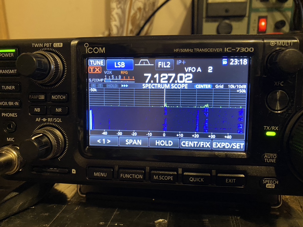
To close the evening off I had a splendid evening enjoying the good propergation and just listening to the QSO’s on 40m. The ICOM’s filter and noise blanker are amazing, SSB has never sounded so good.
The waterfall is incredibly useful for visualising contacts
What i really like about the 7300 is the ability to visualize all or in very close range the frequency. I can easily find conversations happening and enjoy what is being talked about and the signal reports. Almost everyone i hear on 40m is using 100W but the distances are still several hundreds of miles – in particular hearing about life on Guernsey was very interesting – seems they are Covid free and back to some ‘normality’.
Well, heres waiting on being able to book my Intermediate Exam and enjoy more contacts around the world !
UPDATE – Have booked Intermediate exam today (13 June) for in August for more time to do a structured revision plan and passing !
Am still planning to finish my Kanga Kit ! making daily progress !
So I have been using Wefax for getting fax weather transmissions. I really enjoy them and also find it useful in seeing how much QRM I am getting on the ‘wire’ so to speak. Recently a gentleman on youtube by the name of “Tech Minds” published this excellent video
Build a V-Pole for weather sats
Now I loved the instructions on this video and it has been something I’ve wanted to do. I asked “Tech Minds” if i could put the V-Pole adjacent to a 2m/70cm vertical, to which he said yes, so i was then on a mission to build my V-Dipole.
I already had decent electrical terminator blocks, so didnt need to order those.
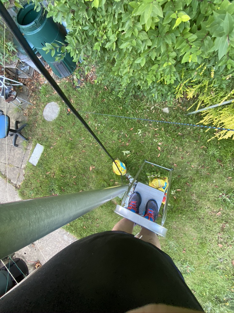
I followed the instructions and set about mounting the antenna on the mast – i have to say i found this quite challenging on my own on how to attach the pvc pole to the mast, but sure enough, and with a few ‘oh dear’ (swearing may of been harsher) on dropping nuts/clamps i got it attached.
I then fed the coax from the mast back into the ‘shack’ where I put a PL-259 socket on .
I do love this video, and the guys no nonese approach
the method i use for puting on a PL259 onto coax.
With that i put the antenna via a PL-259 – SO-239 to SMA cable attached it to the RTL SDR Dongle.
Sure enough, i could pick up radio sounds no problem, so all the effort was worth it !
I then set about installing all the necessary software on my HAM computer, following yet another excellent tutorial from Tech Minds
Setting the software up on Windows
I initally tried with the HackRF, but for some reason it wasnt playing ball. Ironically as I knew that a sat should be overhead, i hooked up my other SDR to a basic scanner antenna, and i could hear the sat overhead ! Immediatly i set about setting up my mac for the receiver.
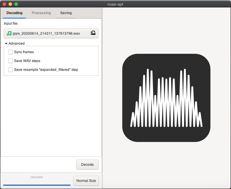
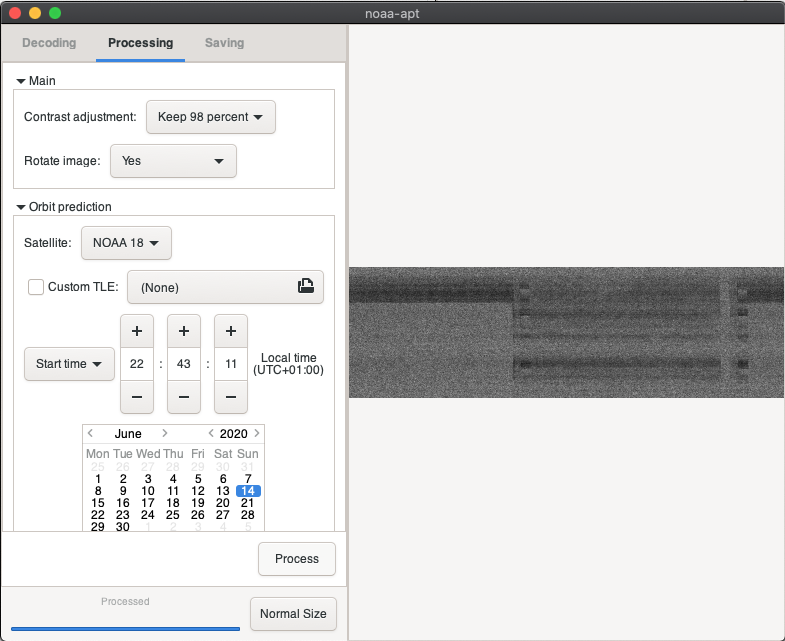
On the mac I used gqrx. The satellite track software is avaiable via macports, but i couldnt find a stable 64 bit version of translation software so used noaa-apt, which whilst not as feature rich, works incredbly well on a mac, as in being actively developed.
I tested with a ‘sample’ NOAA recording, and that produced the required map output ! iwas all set.
I waited patiently for the sats come and tracking and sure enough within an hour i had my first sat pass over ! Whilst the intial result wasnt amazing, it at least proved that antenna, SDR and decoder worked.
My first NOAA decode !
I then looked for future NOAA passes and a good candiate for going directly over was on for 6pm, so i waited and recorded, sure enough, i got a signal and a decode, and whilst the results arent amazing, its a good start in my book.
Second attempt at 6pm
As it was some time before the next pass i set about doing some fettling on the antenna, and found i hadnt got it North-South Aligned that well, so i rotated the antenna and made sure that all the connections were in good form after a full day up in the air.
checking connections
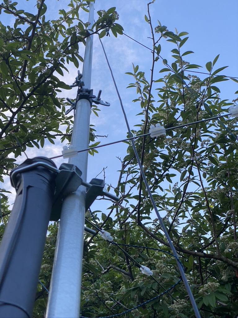
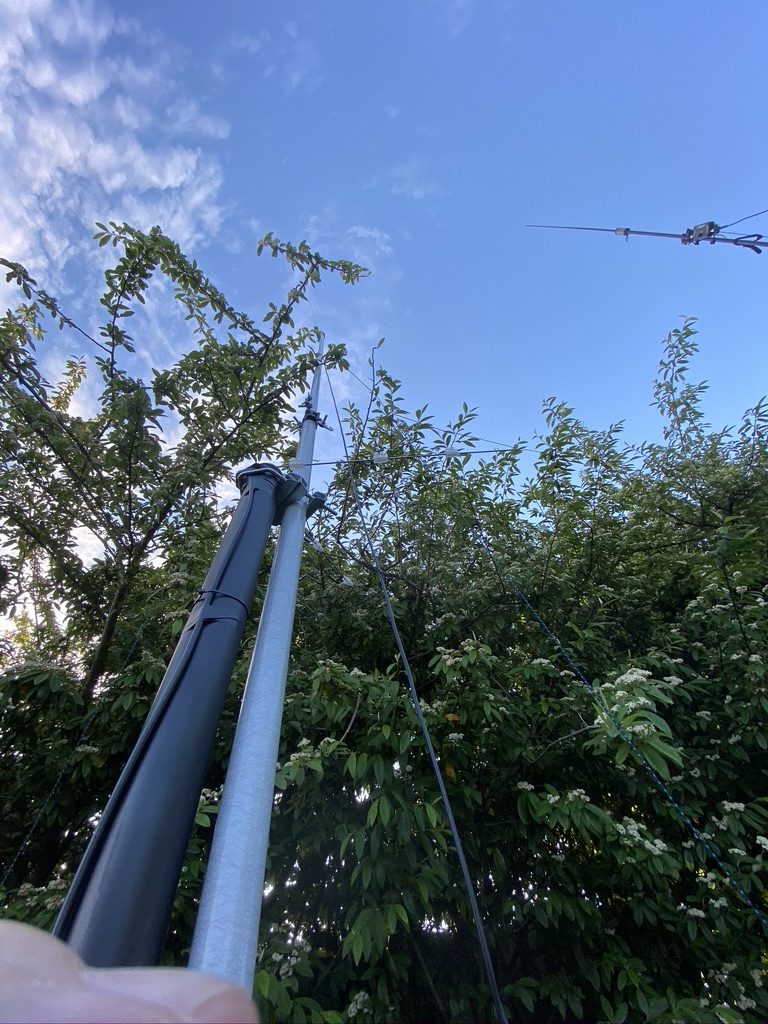
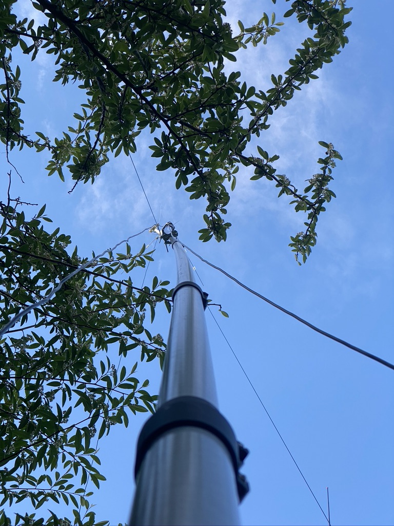
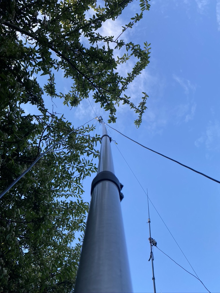
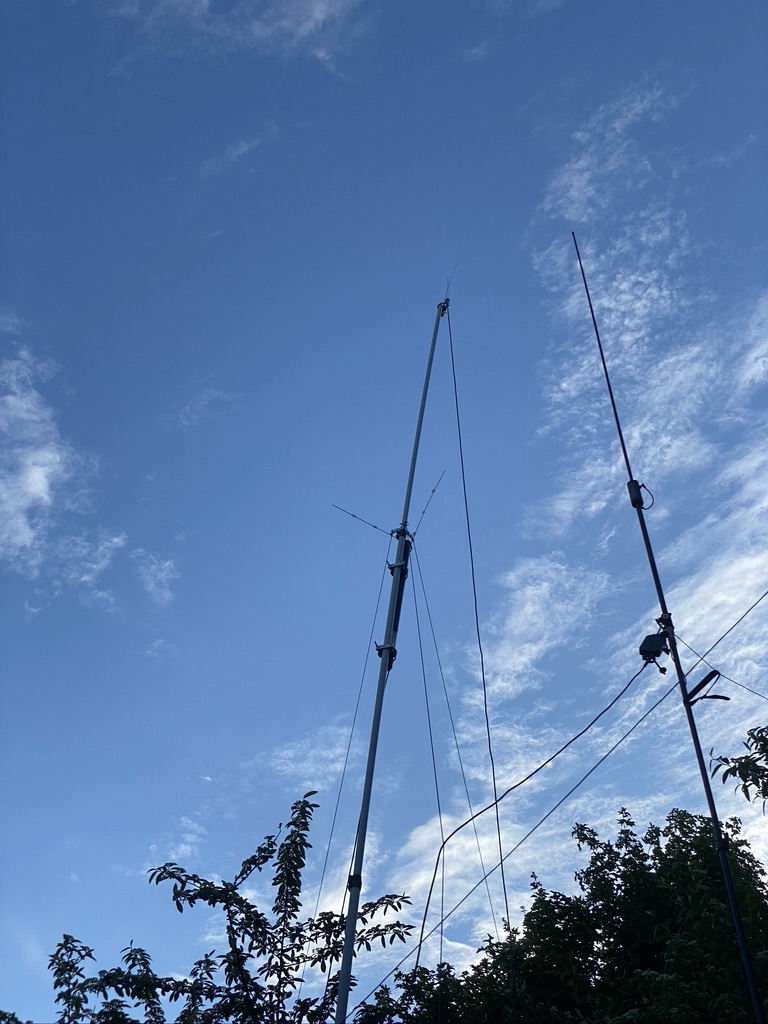
looking good, but those trees !
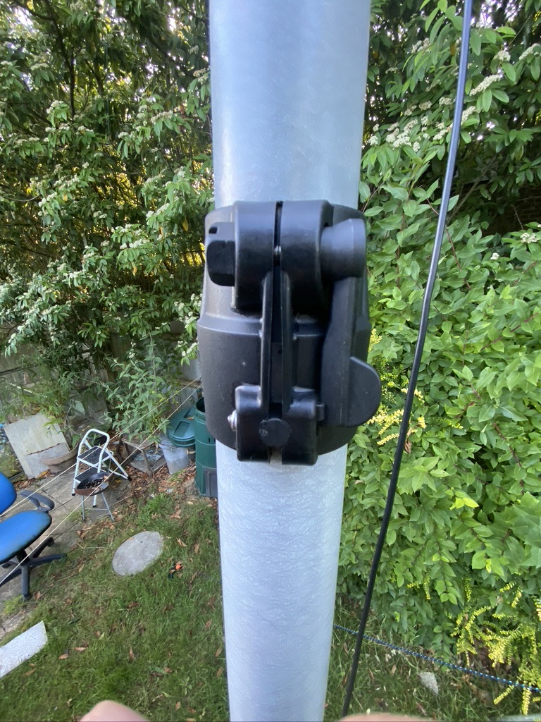
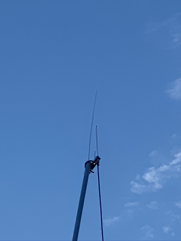
nicely on the mast, but requires orientation
checking after one day
I’ve not really done a write up of just how good the mast is I use for VHF/UHF, but you can see in the pictures below how high quality it is. All the stages are locking and push up/down without problem, even after rain, they is no fricion on the joints. The locking mechanisim is tough, but gives real confidence the pole isnt going to slip down. I use a ‘light’ guying system as i’ve only got 2 very light weight antennas on the mast (the 2m/70cm and now the NOAA) – any more would be overkill. The guy ropes and ground stakes are incredbly strong and go into the ground some 2ft at a guesstimate, the antenna only ever comes down for the worst weather forecasts.
If you want to invest in a good mast system i can really recommend these
With the antenna back up I now wait for the next good pass to try out how good the scan comes out. Its very exciting (for me) and thanks again to Tech Minds YouTube channel who puts really great content !
I’ll upload my pics to my STOATOPIC account as I get more decodes
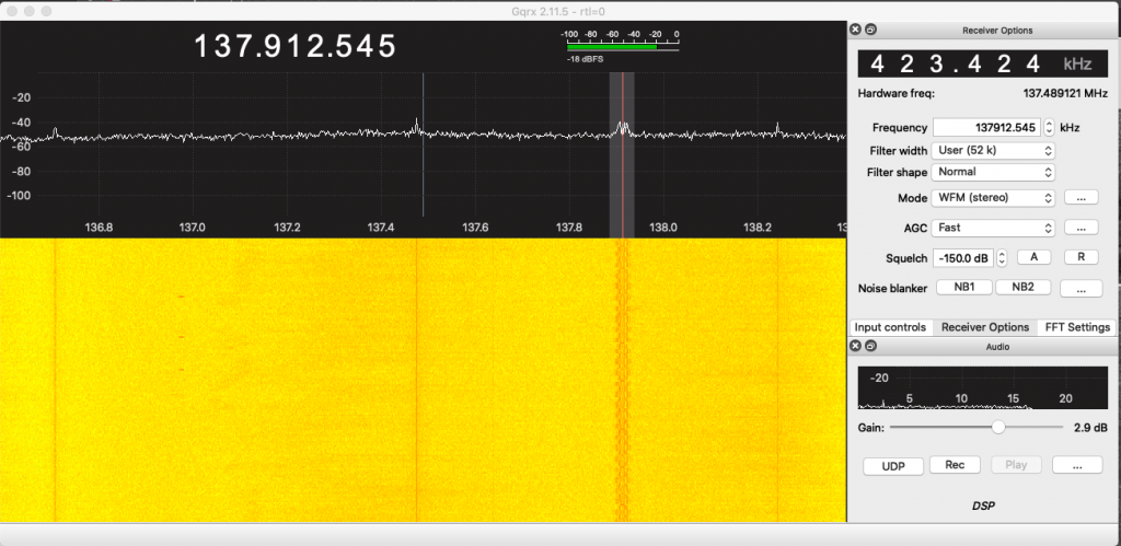
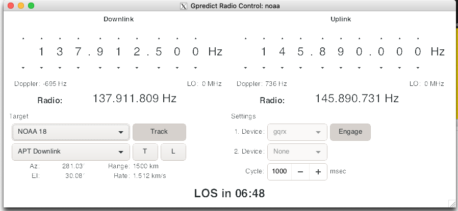
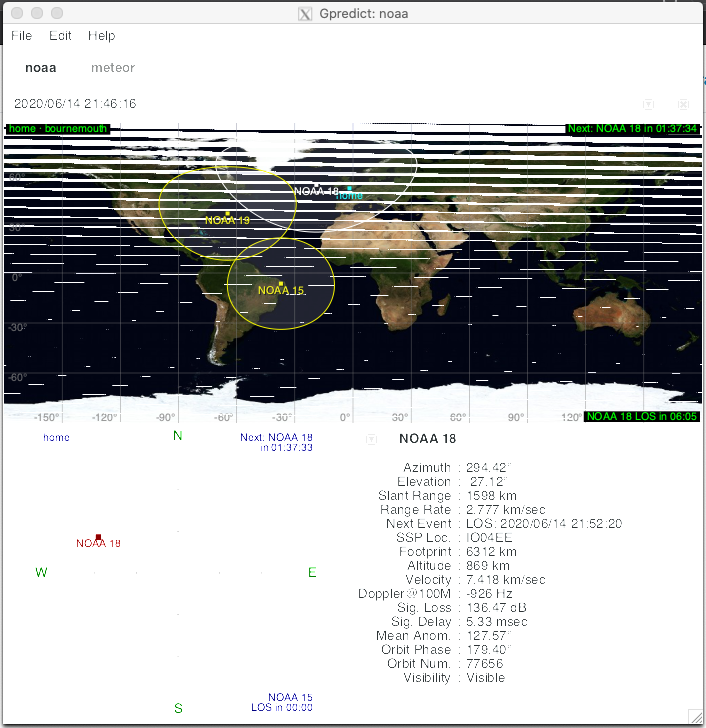
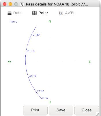
gqrx receiving noaa 18gpredict communcating with gqrxtracking NOAA18 as it flys over my QTH
Tracking pattern
tracking of the pass, i can pick it up from 21:43Decode in NOAA-APTIts another fuzzy one!only the code-strip is visble, but keep trying !
So last night (11/5 – 12/5) Turned into a bit of a QRM mission. Not exactly sure how, but found myself really getting trying to find the source of a specific hum, as I am gradually reducingt the amount of interference/QRM I am picking up. I started with taking my little AM radio (D-328) around the house buzzing very present. What I wanted to rule out was the utilitys nearby and the garage. Being 1AM and wandering around with a pocket radio should make for amusing footage on the overnight security video from the garage today 🙂 Anyhow, I could pick none up.
I returned home,sure enough the ‘buzz’ was back. So as it was quiet in the house (trust me, we are 24/7 shop here!) i started going thru the fuse box, its an older one, but still thankfully a trip/RCD (?) type box where I can easily flip the circuits. Sadly the circuits are not labelled, which I find quite unprofessional, apart from the ‘light’ fuse. I started flipping fuses and on the 5th one the buzzing on the radio stopped, as did all the mains power to my study and I think the front part of the house.
I set about unplugging everything in my study with the mains back on, hum still there. So I started to research/googling hum between 50 and 500Khz – it seemed so precise, I figured it must be some form of ‘man made’ interferance.
Here is a video of what it sounds like :-
So you can hear it all the way up from 50kHz to a very loud abrupt end at 500kHz. I set about googling as to what that could be, and sure enough found th GM4FVM page on ‘power line adaptors’. I’ve been very careful to remove and limit the use of ethernet in the house now, so suprised that this had caught me out. I immediatly removed the BT Ethernet over Power adaptors I had. This is the result
A longer video with manual AM tuning and a ‘sweep’ of USB
If you are patient enough to have watched the whole video, i congratulate you 🙂 But you can hear the big difference between what a power line adaptor can do to HF/RF in a shack, i.e. completely destroy all but the strongest signals.
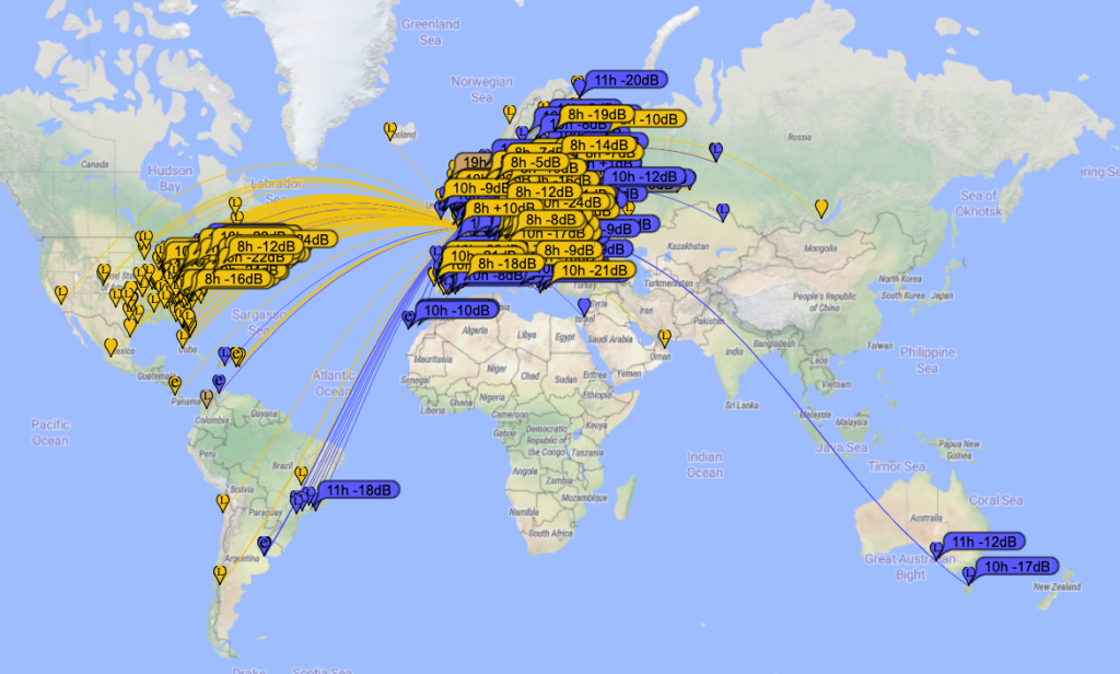
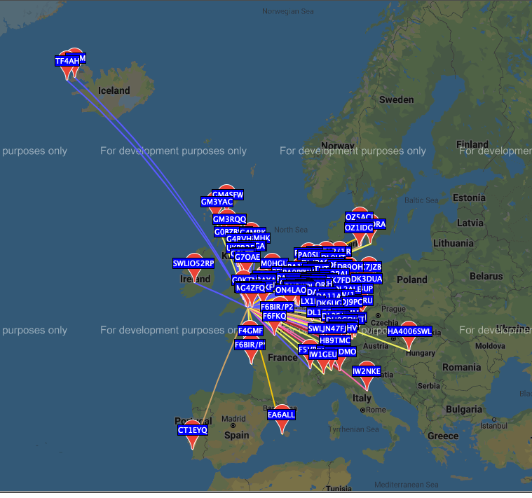
This morning I tried out WSPR, the results on receive and transmit speak for themselves :-
wspr map is somewhat busier…
So now its time for work but I think i have taken another big step in reducing QRM in my shack