So it has been a gorgeous sunny day with little to no rain down here in IO90BS today, of course it being a work day means that I am kept very busy ! However I do get a lunch break and made the absolute most of it !
The decision
So after yesterday was, i dont mind saying, hard work to get the mast up, I really pondered what my next steps are. The days are short, the weather, mostly wet & cold, doesnt lend itself to antenna building like those lovely long sunny days of being able to put an antenna and still have sunlight after it.
I watched Callums DX Commander piviot video, many, many times in the evening – and i thought, this has to be the way for me. On my own, getting an antenna up and down, i have to have as much help as I can get where engineering can give me that assistance. This was about 11:30 a night, and most of my sensible friends are asleep at that time, or at least wouldnt want to be disturbed on a Sunday night about ‘is it a good idea to build a mast tilt DIY’ so couldnt get a second opinon.
https://youtu.be/v0xrqmoKC_s
Tilt Over Vertical Nebula base by Calum
The build !
I asked my good friend, who we shall call ‘John the Brush’, some thoughts on the video. He is very capable and building and generally ‘making things work’. He was very quick to identify the required parts, which is something I couldn’t do after browsing B&Q and Wickes last night.
“he made that from a bit of M10 st4udding and some 100 x100mm fence post” – now i don’t know what M10 studding is, but B&Q sell it and it looks like the pole that Callum put thru the wood.
I’ve now ordered the wood (From Wickes) and the M10 and nuts and bolts from B&Q, total cost – £42.04 (including delivery). I have plenty of tools, although i have to say i love that Makita drill that Calum uses in his video – what an awesome bit of kit that is – i’ve got a Bosch SDS drill which i think should be able to do the same job.
So, that gives me a short-to-mid term plan for the Nebula, but what about NOW ! I dont like being off the air, it was hard work to get my lience and its a nice enjoyable, relaxing hobby (well putting 18m masts up can be a strain…)
The NOW
So I was pondering, what is the quickest antenna i can get up in the small window of time i have for lunch. I thought about and started getting the bits for the classic – i’ve got all the wires and can get it up and running pretty quick, but things can, and do go wrong.. Whilst i was untanglilng all the radials, i spotted my 40 meter dipole, and remembering Tim (G5TM) had just done a recent video on dipoles.
Simple antenna, quick to put up, and respectful performance
Dipole it is ! I had everything ready and could get this up pretty quick.
40 meter Dipole
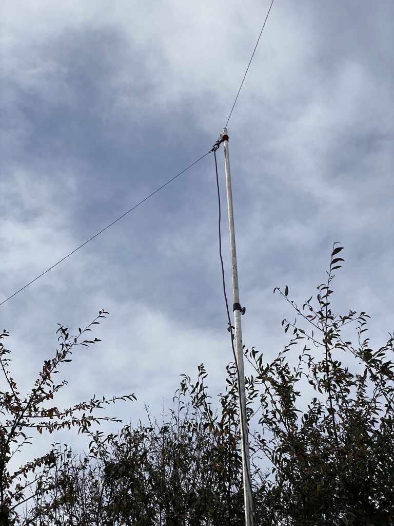
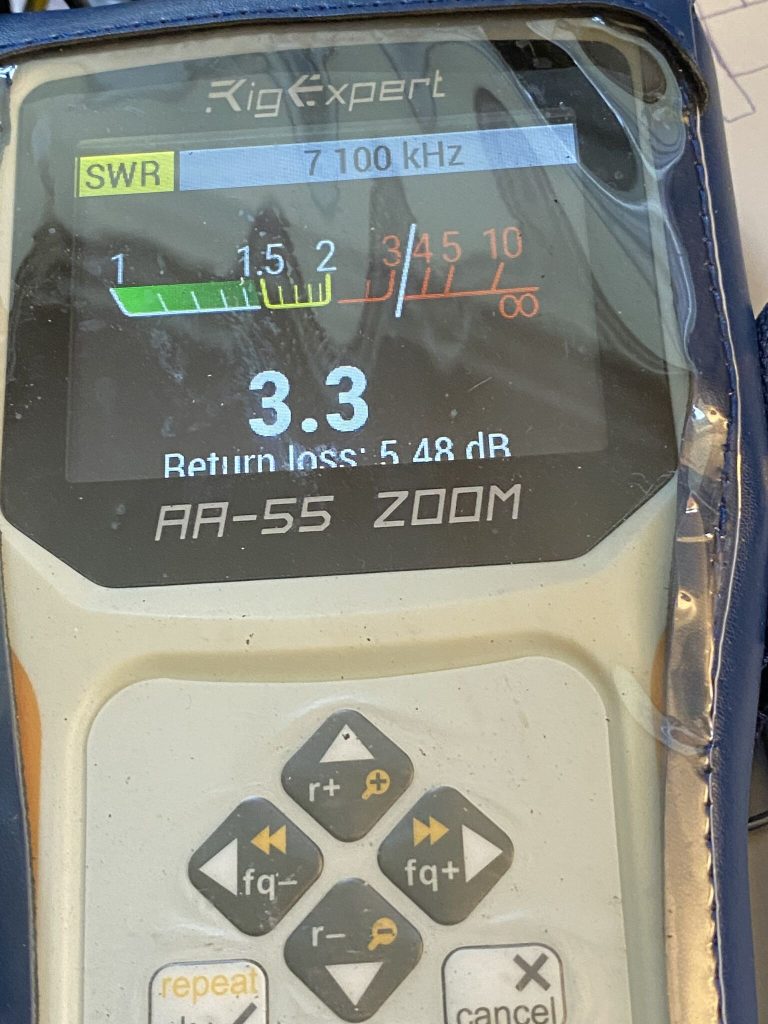
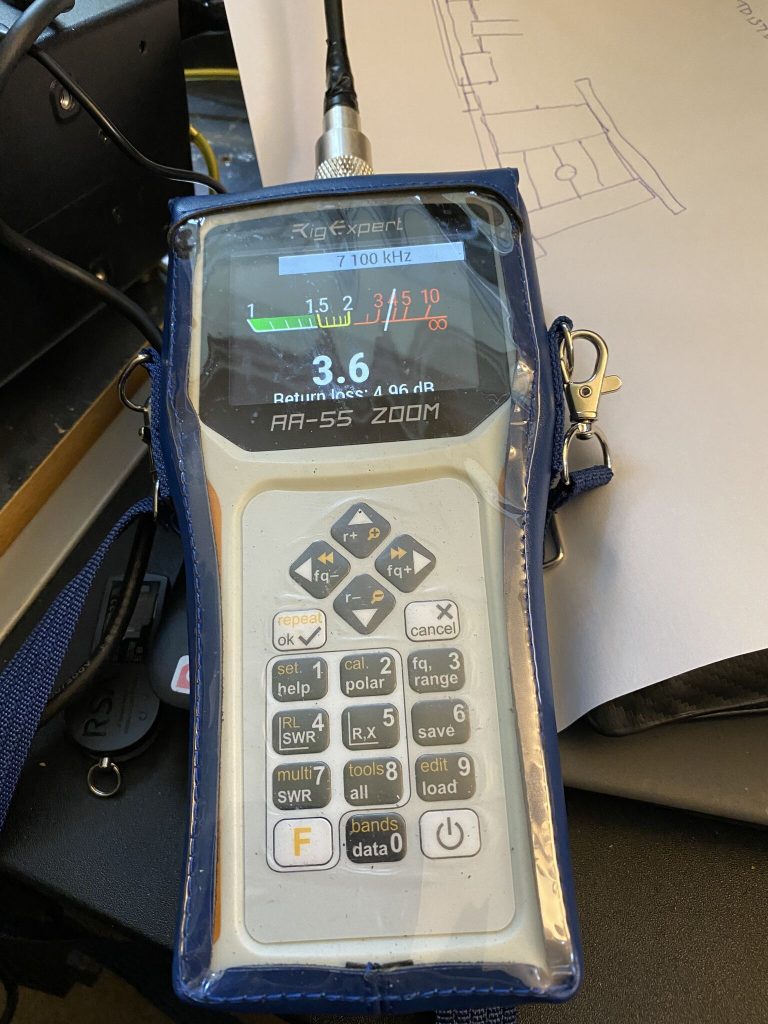
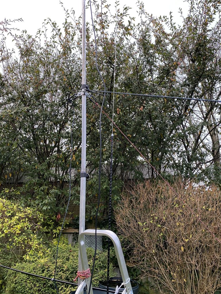
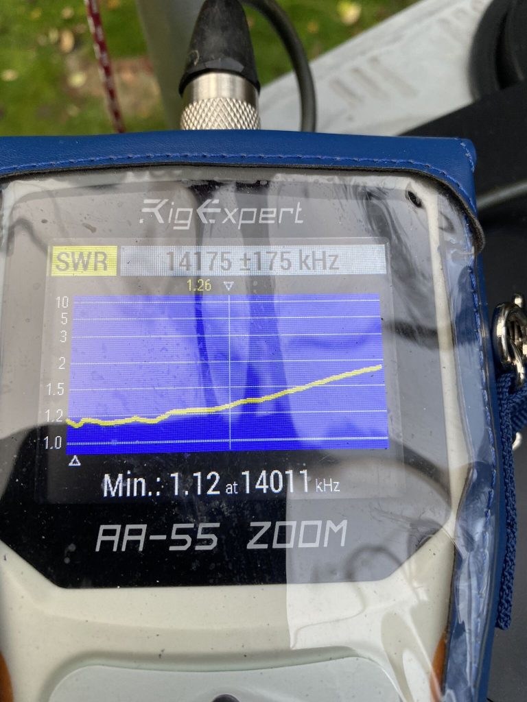
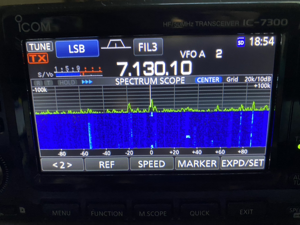
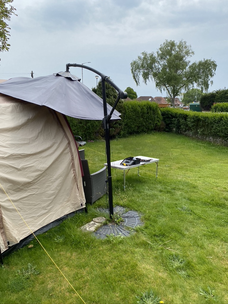
With one end attached to a washing line, another to fence post, it got my 40m antenna up in the air ! Now, time to see, how is the SWR..
A little high, but the ATU will manage it
So i only had so much time, usually i’d be looking for between 1.5-2 on the SWR, but 3.3 was good enough – i did have to reposition the right-arm of the dipole as it was just touching the mast, that did get the SWR down a further .3 points.
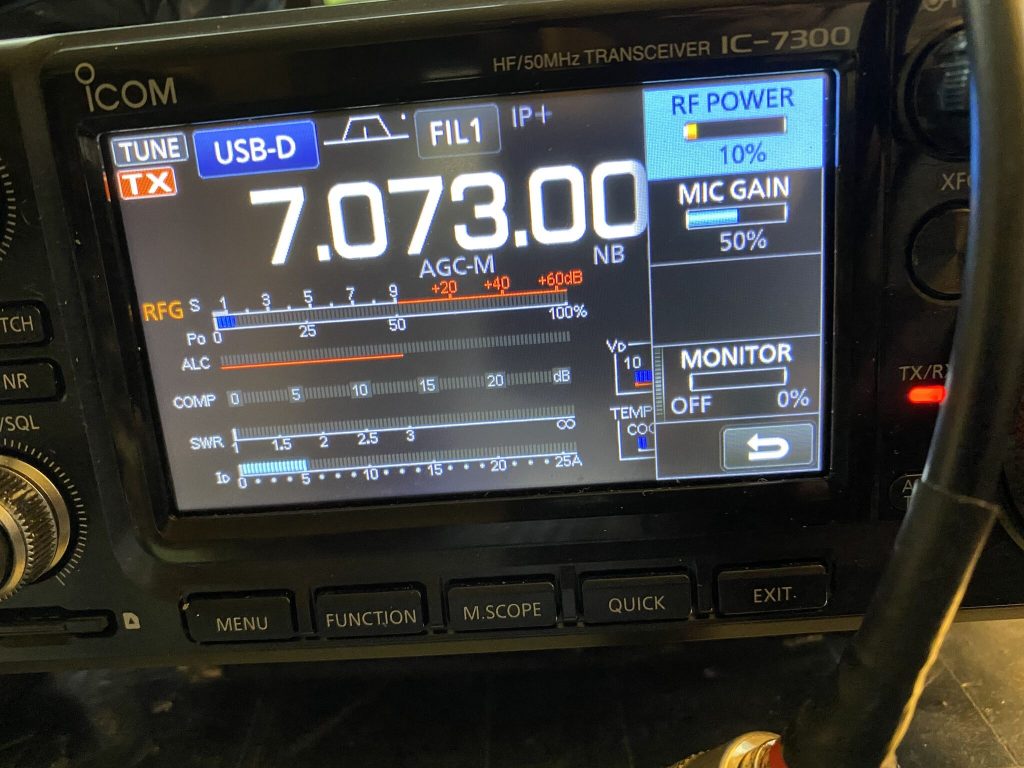
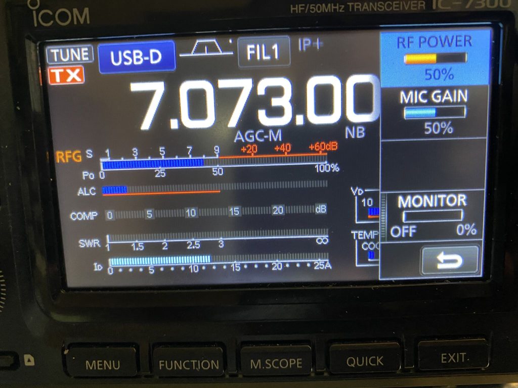
I went in and put it on the 7300, sure enough I could hit the ‘TUNE’ button and SWR was restored to 1:1 – this is on the 7300 internal tuner !
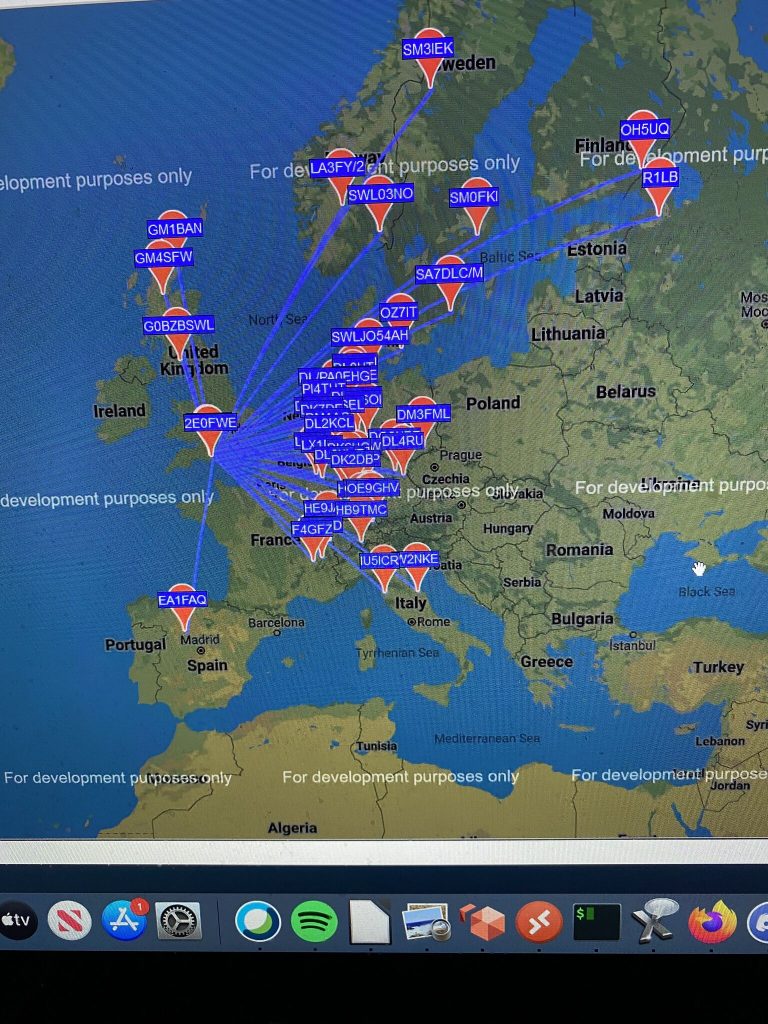
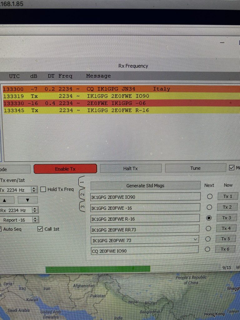
A quick test on FT8 yeilded positive results !
30 Watts into a inexpensive dipole gave good results, even a quick QSO !QSO with I1GPG via the 40m dipole
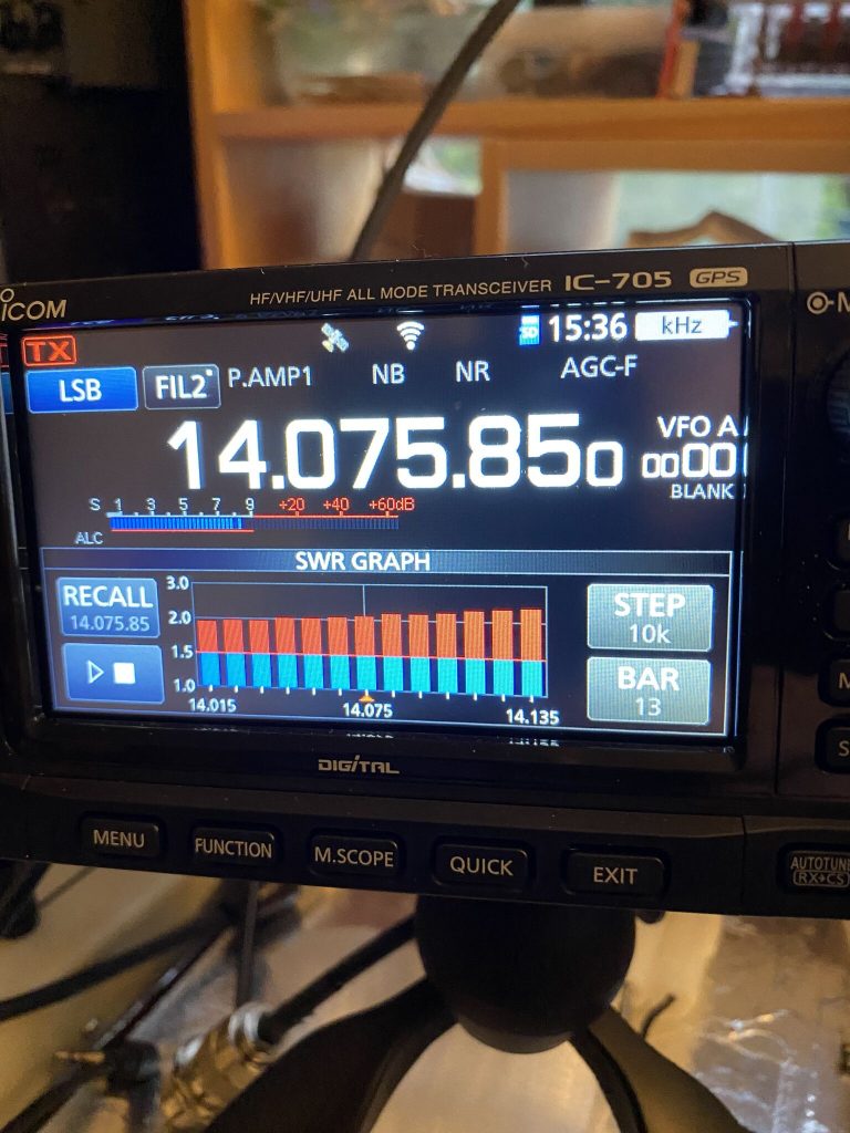
What a result, for less than an hours work, i was back on 40 meters. Then I eyeed the 705.. could i use that with 20m ‘whip’ on the mag mount ? hell, lets give it a try !
results on 20m for such a quick setup was impressive
This really was ‘plug and play’ antenna, the mag-mount is on my step ladder, which gives some support (it is guyed as well) to my dipole mast. The SWR results on the 705 were slightly higher than the Rig Expert, but still not bad for such a quick, and somewhat crazy, setup.
I was able to tune FT8 audiably, but have nothing to receive. Next project – Raspberry Pi 400 on the IC705 !
Conclusion
So I’m back on air, able to enjoy listening and transmitting on 40m and potenitally 20m as well , as well as a fix in plan to get the Nebula up. I’m really happy that i can quickly get back on line and also progress the Nebula.
Hopefully tomorrow I will be able to test 20m in the day, even WSPR would be amazing, at a push FT8 ? (FT8 requires working/engaging with the app, I’m working in the day).
Big thanks to “John the Brush” (who is a ham, but doesnt go on air!), Tim and of course Callum !
So as predicted, its been typical English weather here today, drizzly and cold. I bumped into a neighbour and we was discussing how “spring” like it was yetersday.. and the forecast doesnt look good for a while..
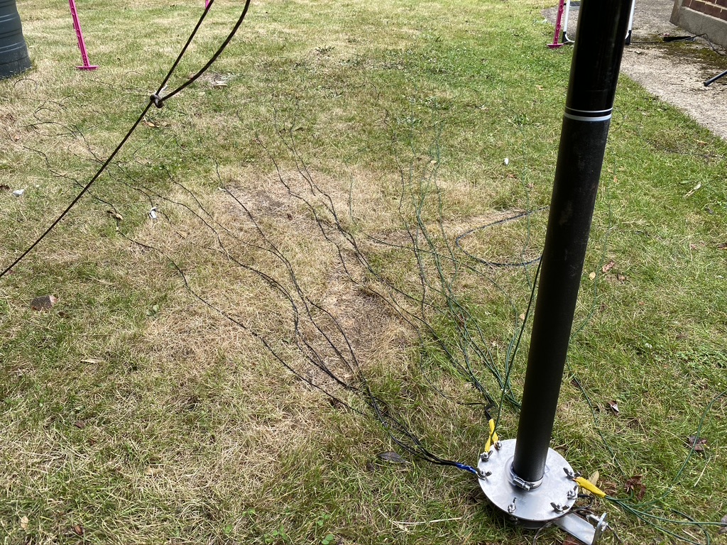
So what did i manage to do today – well long and the short is that after a couple of trys i *did* get the nebula vertical and guyed in, but the wind and rain was really taking the toll on me, so i had to pack up for the day.
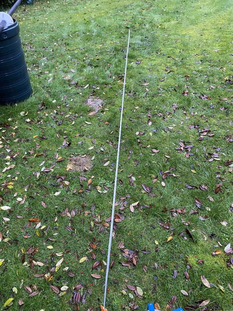
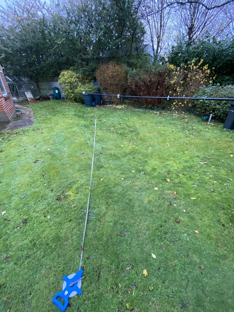
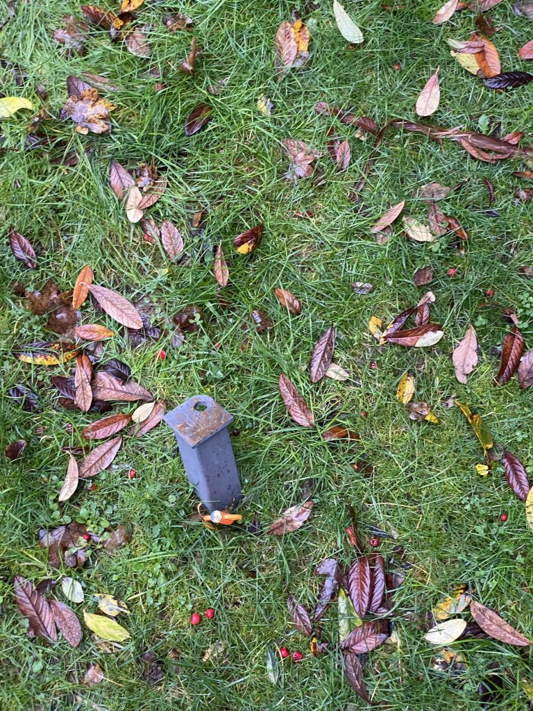
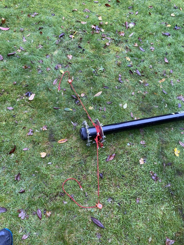
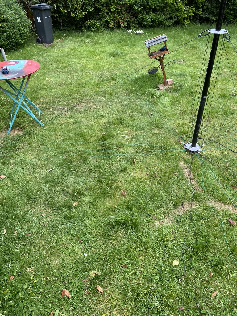
measuring the guy-stake positions
I took the 120 degree pattern and 5m distance for the stakes so (hopefully) my measurements for the ropes would be long enough.
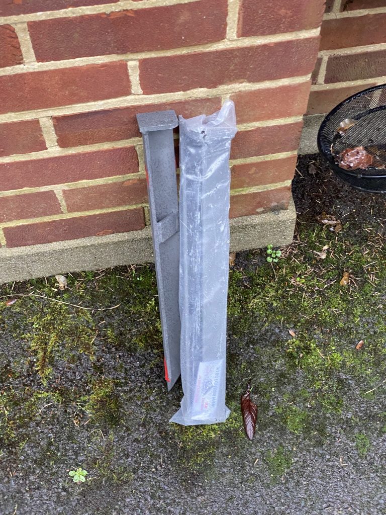
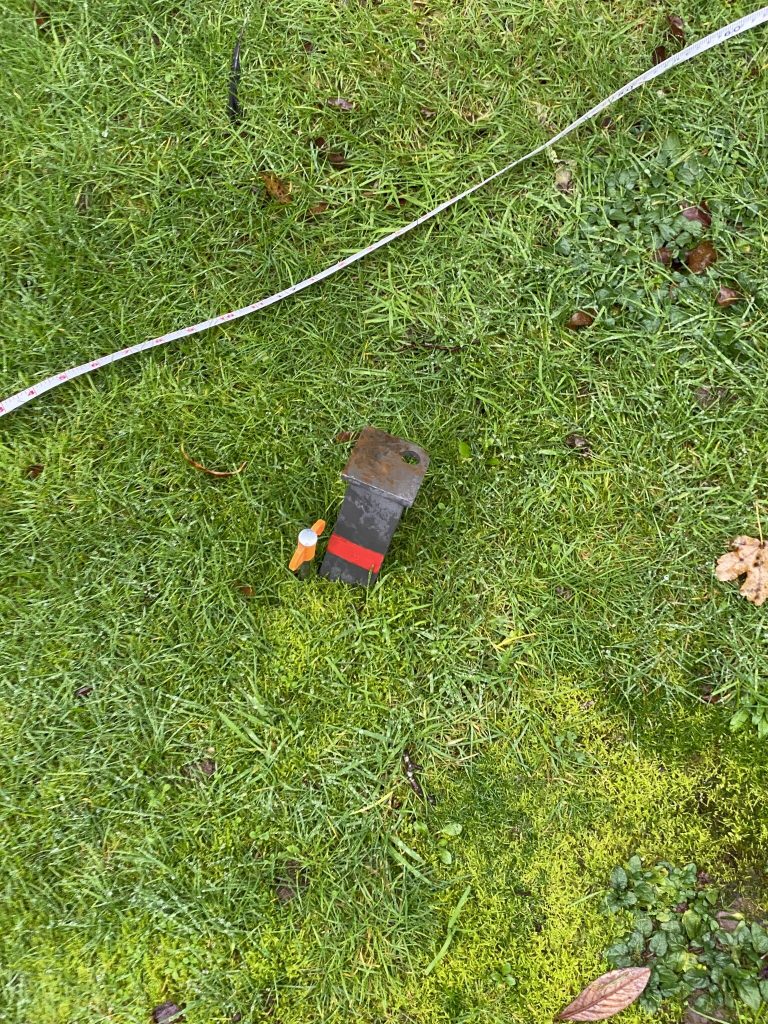
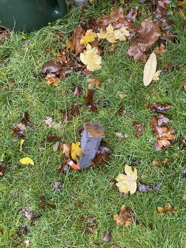
stakes inserted to a good deapth – one good thing about the wet weather !
One area where the wet weather did help was being able to get the stakes into the ground, as you can see from the first pic, these are not short at 18″, a good club hammer got hem into the ground nicely, so it was a positive start after measuring and getting them into the ground easily.
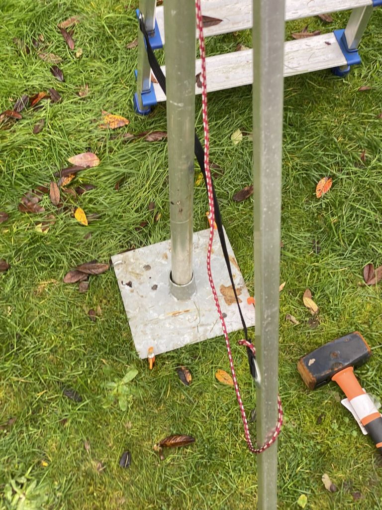
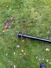
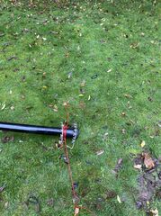
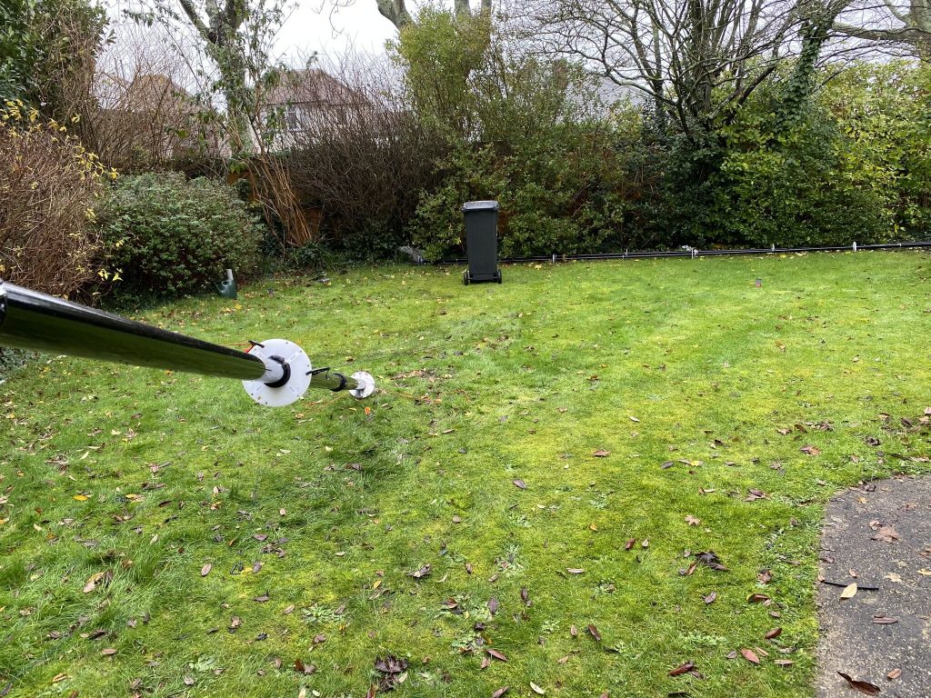
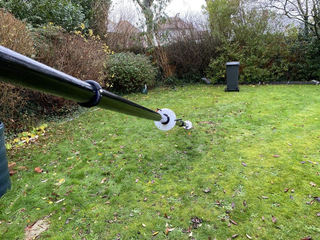
the struggle beings, but some progress !
I really struggled for about an hour with getting the mast up, its really heavy and i was getting no traction. With a classic i can get it up no problem, but its much, much lighter than a nebula. I was somewhat at a loss as to what i was doing wrong ! So i went back and RTFM’d, in it sugest using two ropes as a ‘2nd man’ on the base. I done this and that at least started to get the mast in the air ! huzzah – but now the guy ropes wouldnt reach 🙁 bummer. So i repositioned the mast and ‘2nd man’ and finally was able to get the mast vertical !
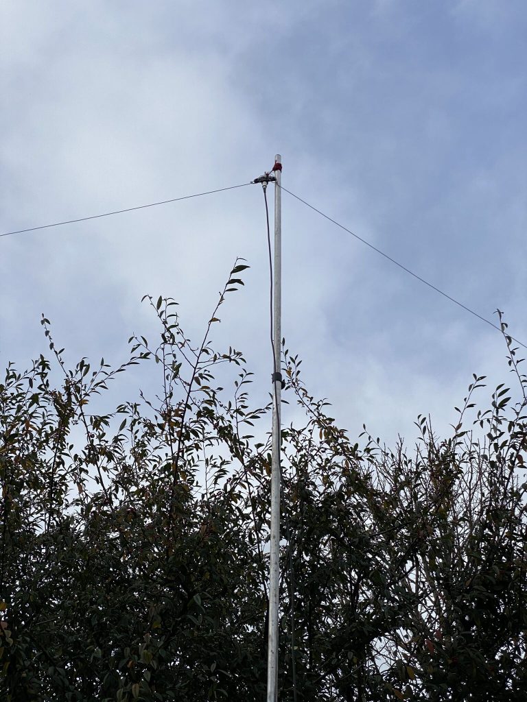
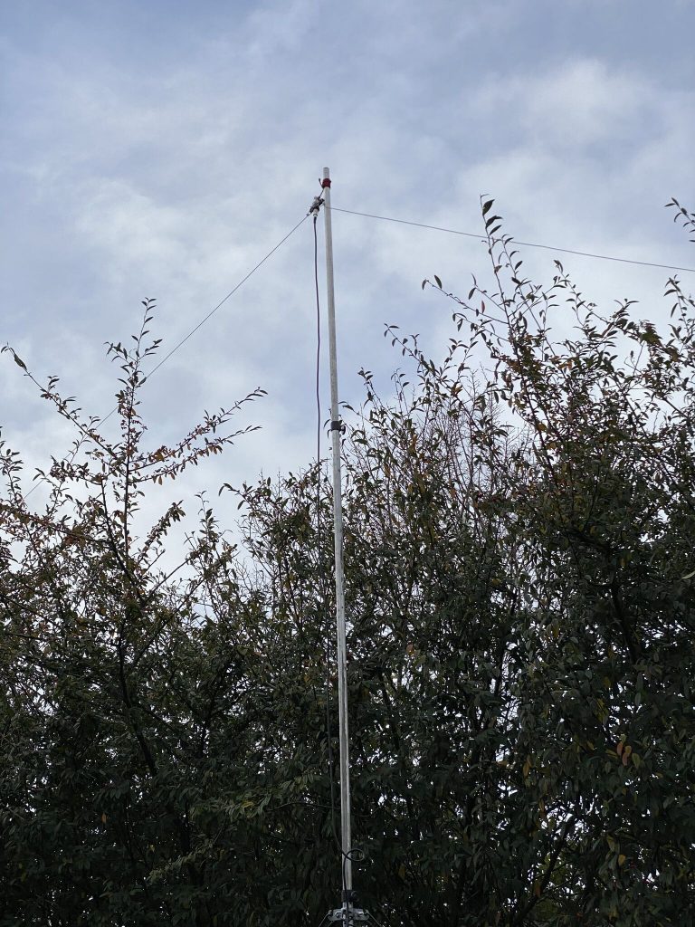
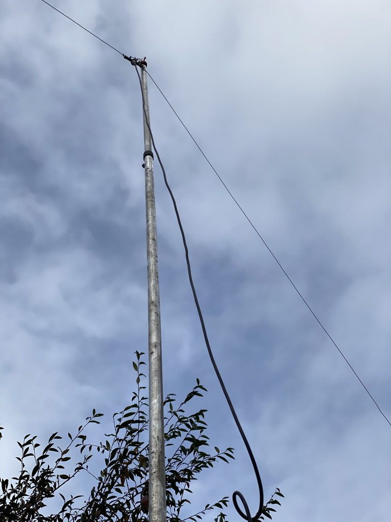
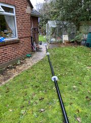
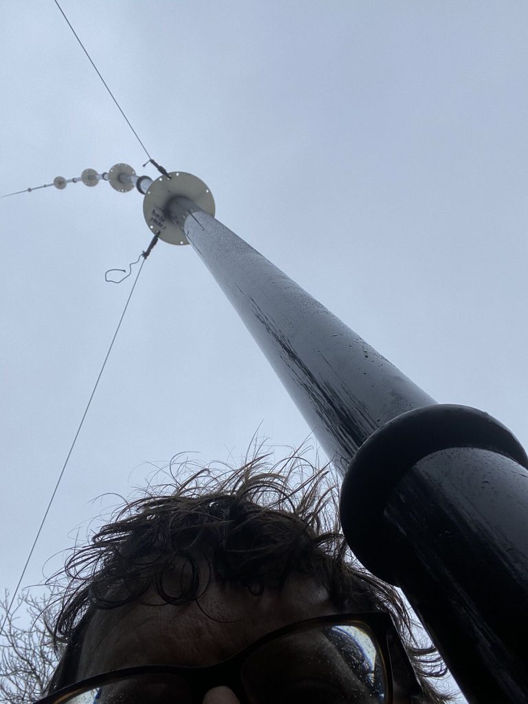
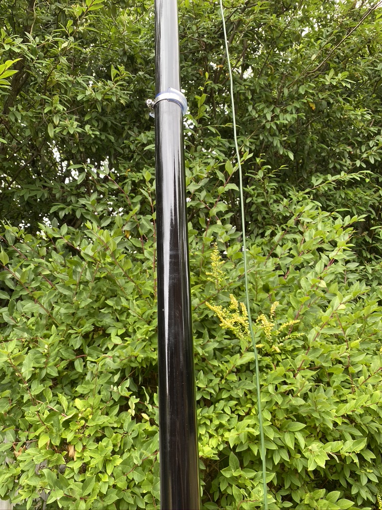
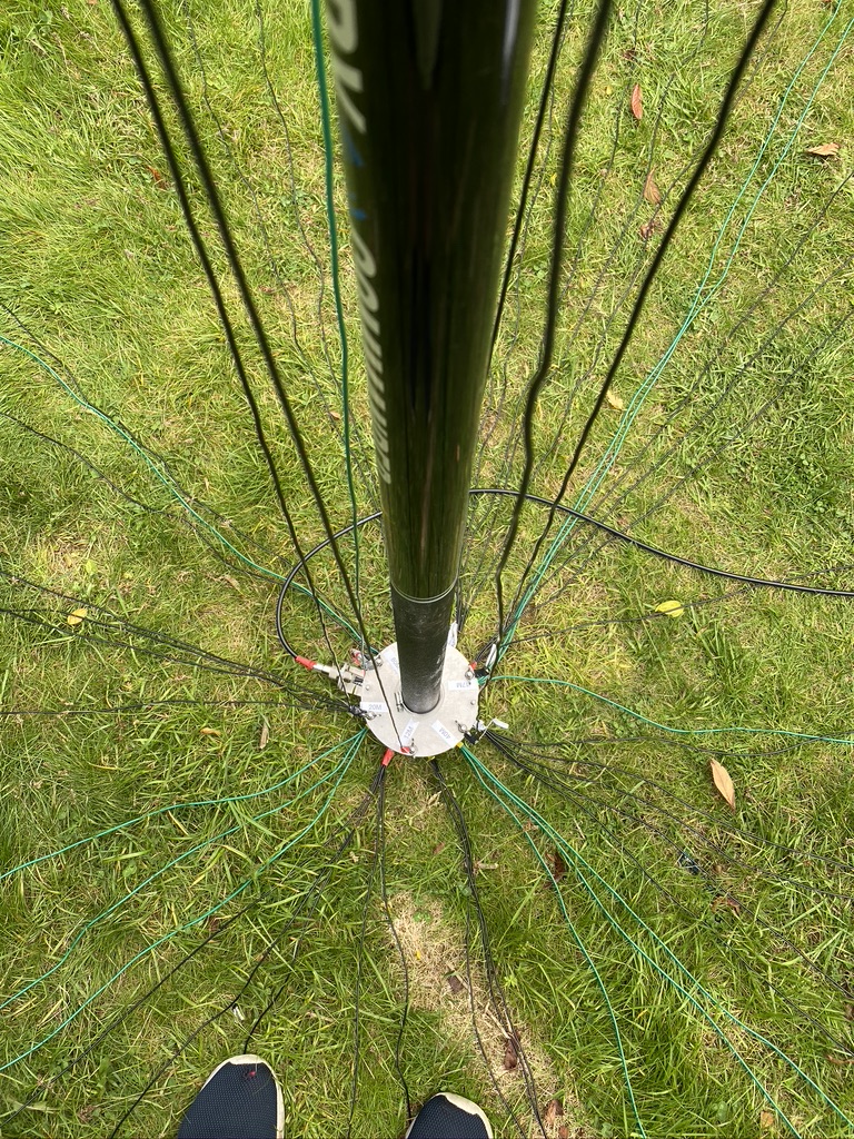
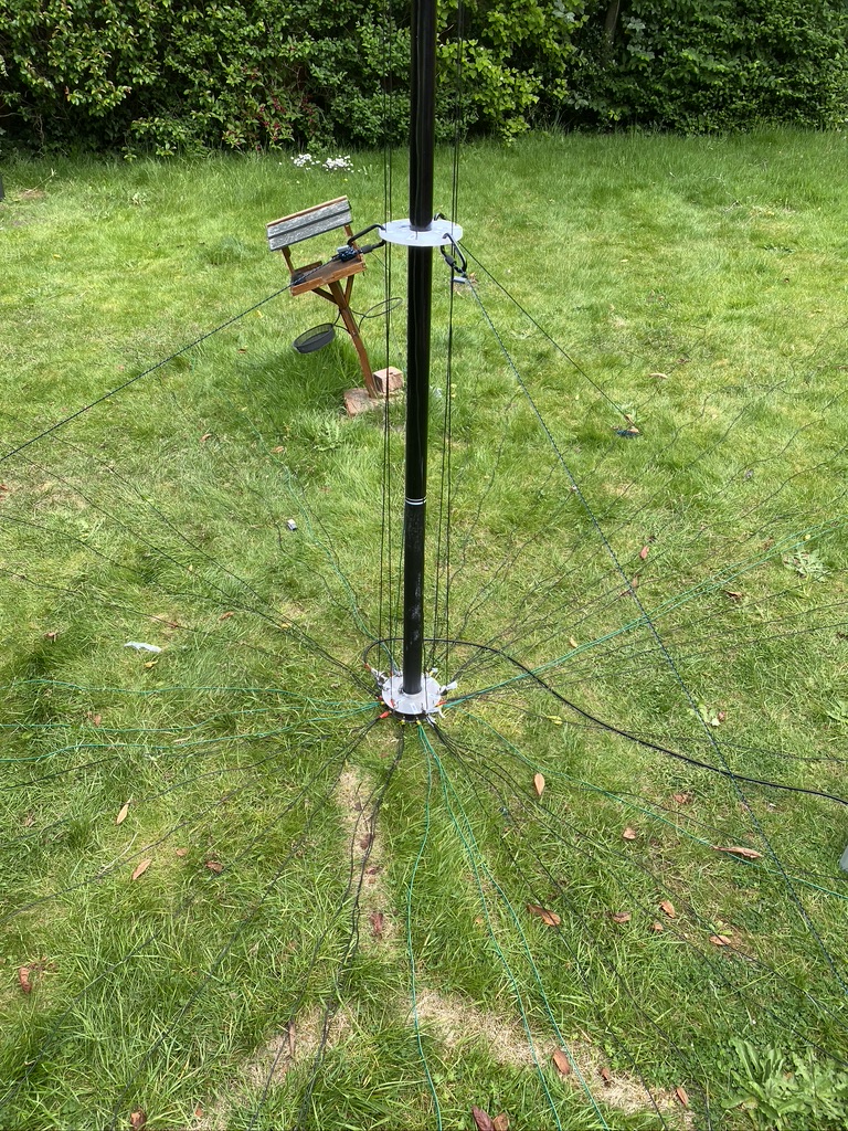
Nebula in the wind and rain, its up but its coming down pretty quick agian !
I was happy that i could get it vertical and on the guys, the wind was having a great time vibrating it like heck, and as you can see from the top of the mast was really wanting to send it over – guying the nebula at 3 stages is giong to be a minimum IMHO, anything less, you could end up waking up to a mast on the ground… or worse !
So to conclud whilst I’m ok with todays progress, it leaves me asking some questions. I follow the weather and when there is a warning, the mast always come down (see previous blog postings) – the Nebula is always going to be hardwork to get it up and down as easy as a ‘classic’. I can ask friends for help to get it up the first time fully rigged, but what when I need to get it up and down myself ?
I’m thinking to make the most of the bad weather, get a classic back up, but with M&P cable/connectors, and follow Callums example of a tilt base over the next few weekends, at least that is something I can do in the ‘garage’ in the dry and will mean getting the mast up and down is that much easier. I dont think any of the ‘commercial’ tilts will take a mast with a 3″ diameter, plus adding on more (i would estimate at least £100, if not £150) to the atenna the costs are going up.
I will sleep on it but i suspect the English weather and keeping to a budget on these things will decide for me.
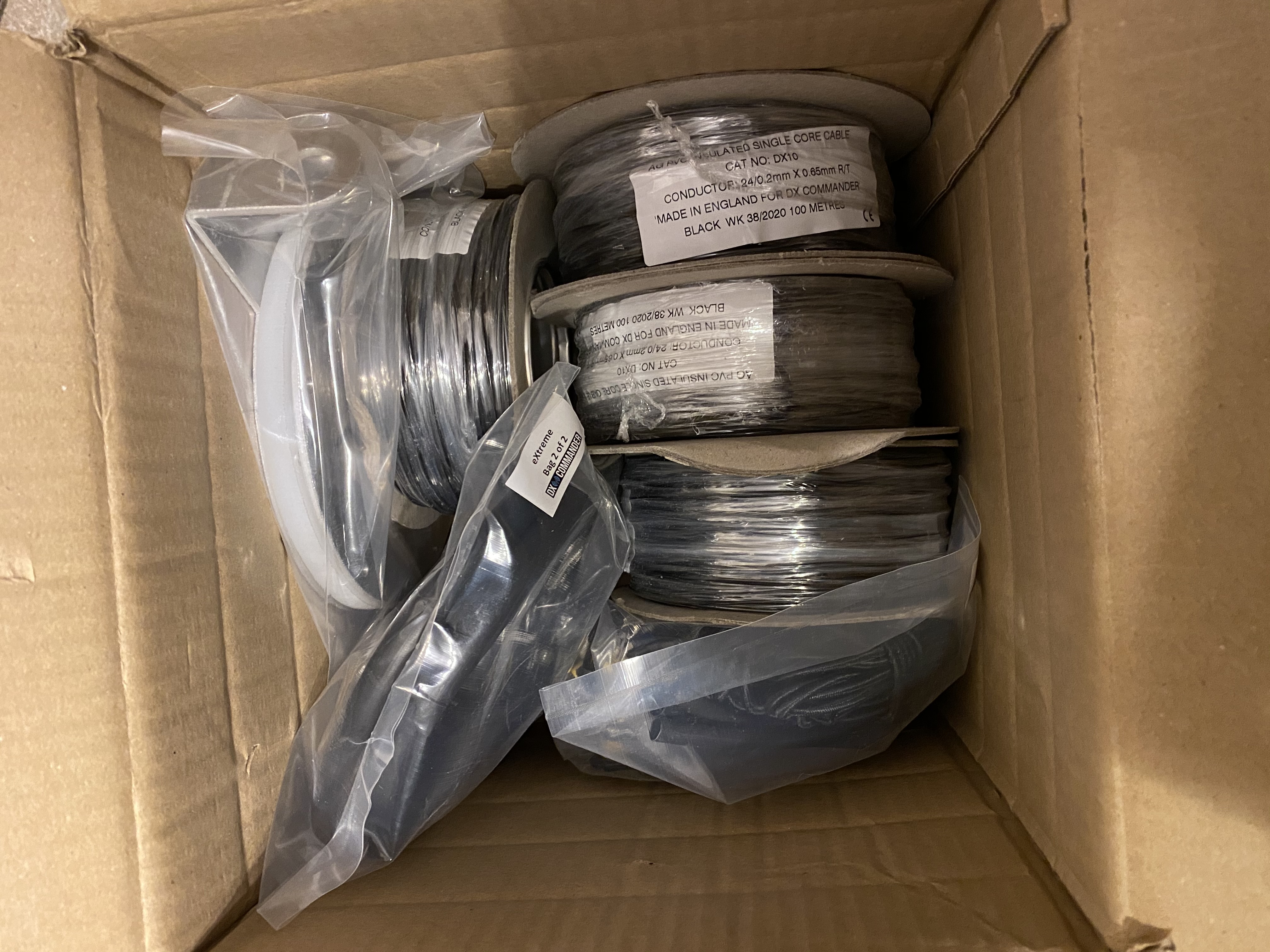
To give its ‘full’ title, that being the DX Commander 18m eXtreme, has arrived ! Very well packaged and thankfully unharmed in transit.
The packages came on two separate days, but well tracked with the couriers used by Callum.
The packing was really well done to get so much into a relatively small box.
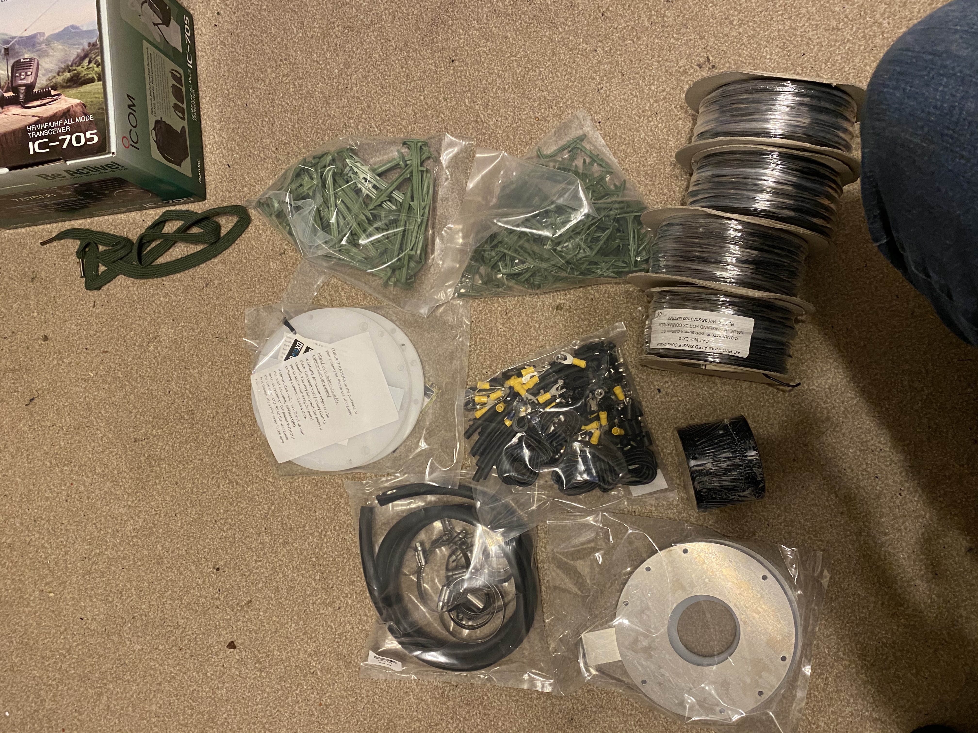
dx commander parts – alot of wire !
Was glad to check that everything (as long as the contents of the bags) seems all there (including guying rope)
Visually, the quality of the components makes me think these will last a very long time indeed. The plates and UHMWPE ‘spreader’ plates are incredbly well made, and Callum is a perfectionist, so can be sure that these will fit the 18m pole really well. I did have to look up what the ‘green things’ were, these are securing the radials – a very nice idea.
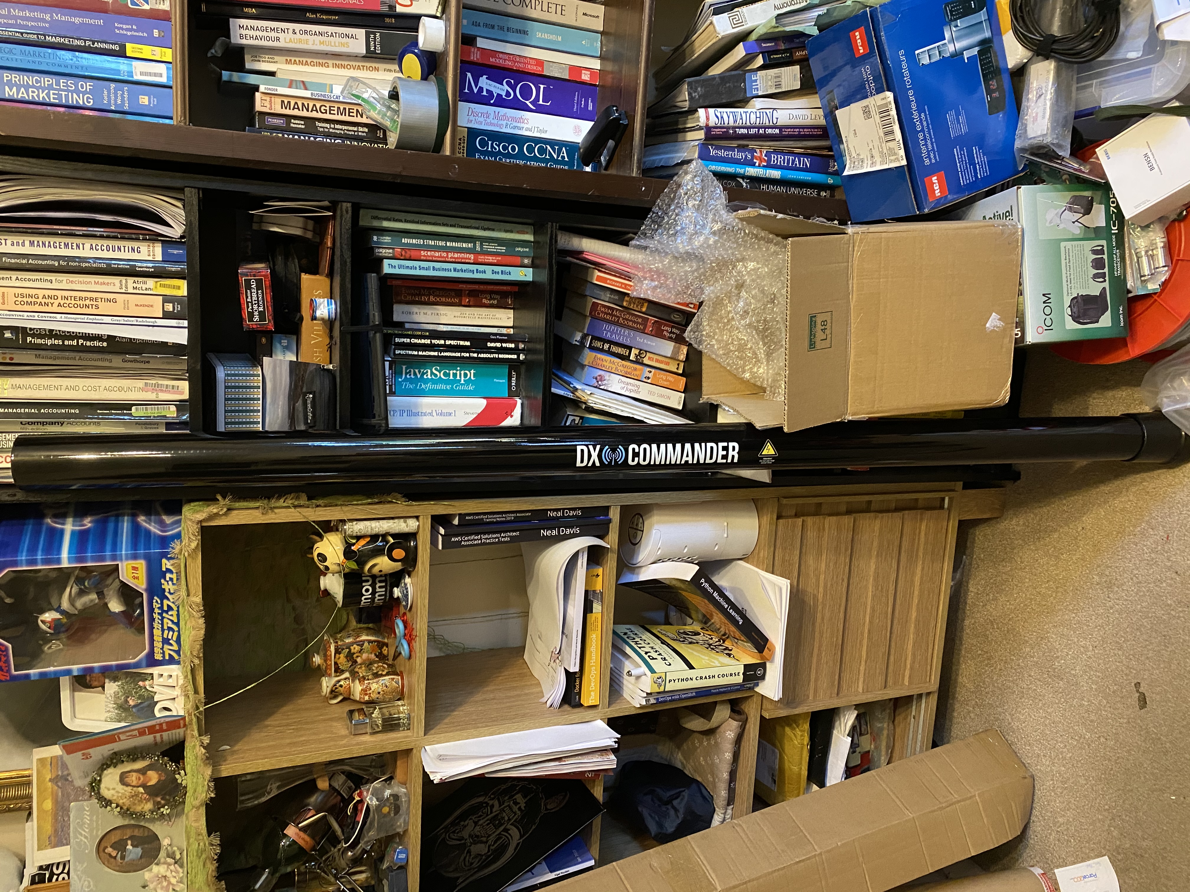
The ‘pole’ itself is quite something, it is quite a weight compared to the ‘classic’ pole, but given the amount of sections, unsurprising. As ever, it looks incredbly well manufactured and will provide many years of operation. Whilst this at my QTH is still a ‘temporary’ antenna, i;ve had no problems with a well-guy/rigged dx-commander staying up. The only time i have taken down is the met office weather alerts for very high winds, and thunder (i dont have a lightening arrestor).
18m pole
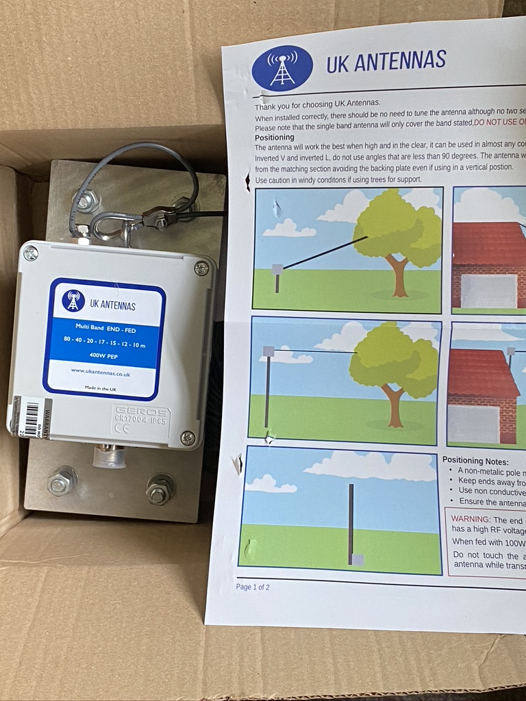
I have done several ‘surveys’ and thinking of the practicalities of building an 18m mast will bring. I’m glad i’ve got several large lawns which will accommodate the build ! I will take a video before taking down the current 80m end fed configuration which has served me really well for last few months. The UK Antennas multiband has been exceptional, and I’ve had many QSO’s – i dare say my antenna is setup far from optimal, so its all credit to the UK Antennas build that i get out with very low (i.e. mostly 1:1 – 1:3 SWR) SWR readings.
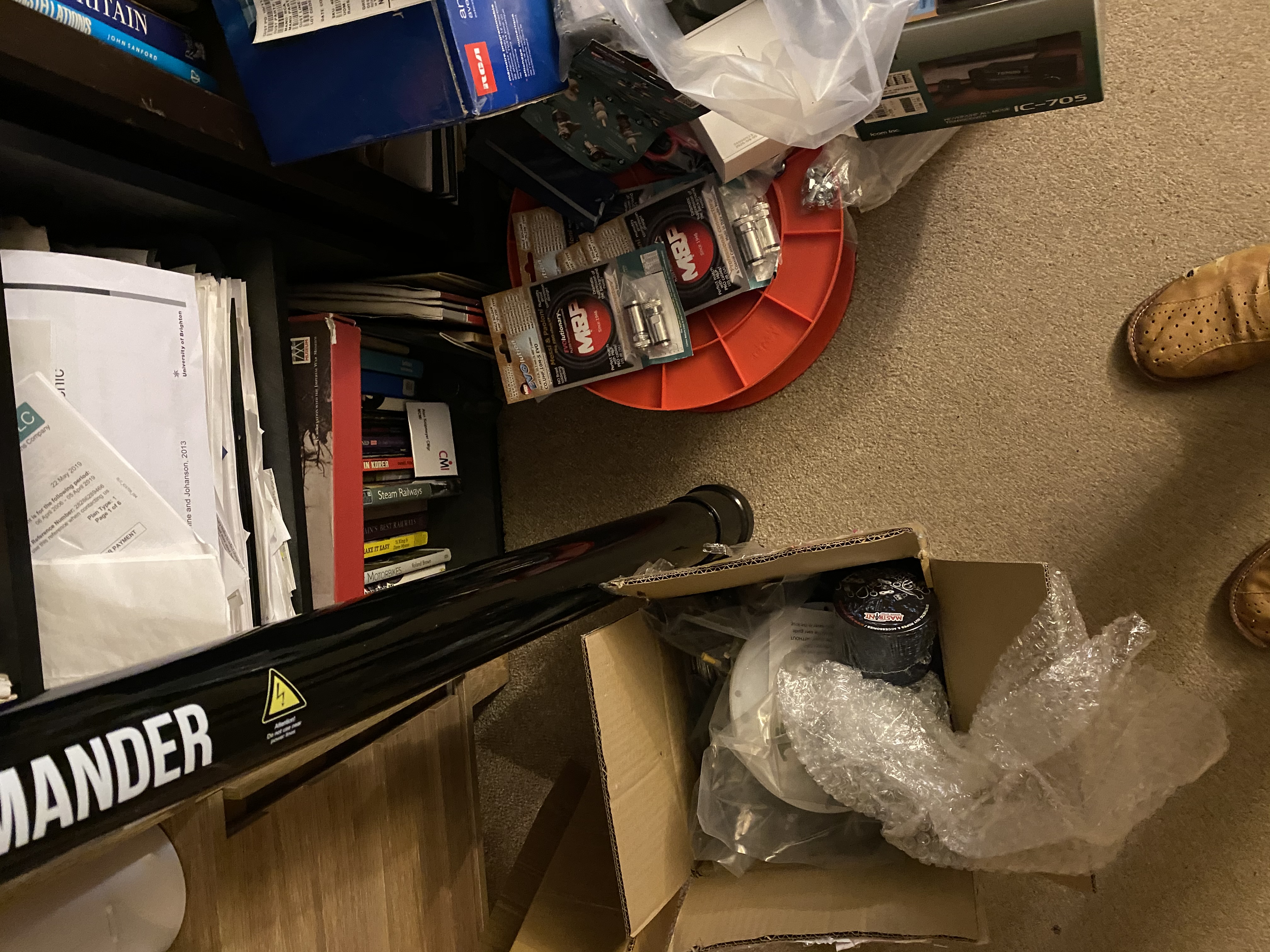
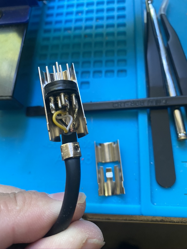
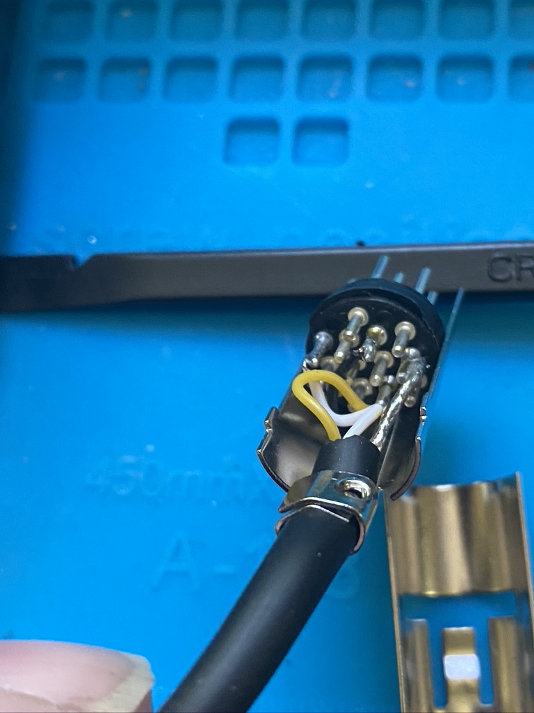
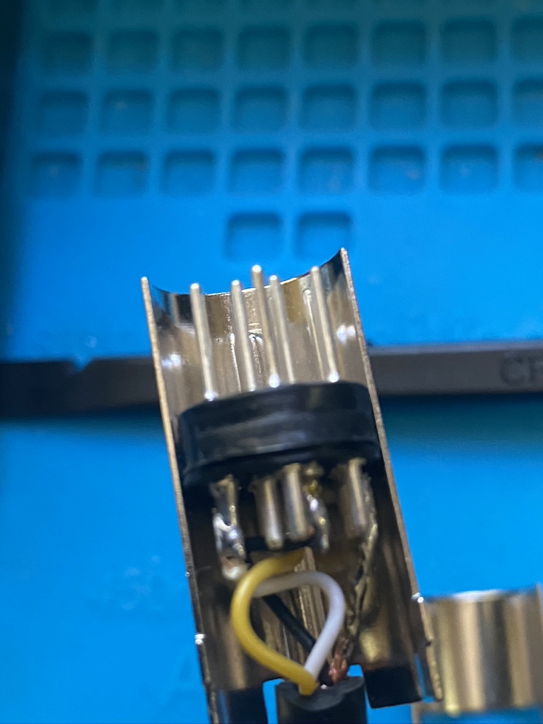
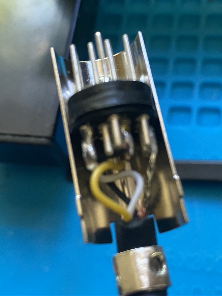
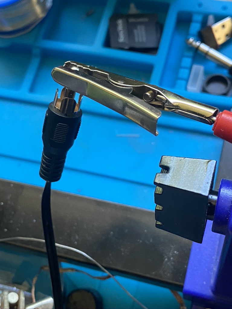
good quality cable land connectors
I have up until now being using, whilst not bad, not exactly the best/recommended. So I will be using M&P connectors as well as Ultra Flex 10 coax measured to good lengths (as in not too long, not too short).
For now i am reading the instructions carefull, learning some new knots to help with the guying and will make that video before the weekend, when the end fed will come down and construction hopefully start !
Been off the radio for the last week or so for exam revision (passed, if your interested its for IAC Terraform). Am waiting for the Nebula to arrive, so not been able to post about making cables, etc. I dont really want to use the new cable for the existing antennas, will see what is left after the nebula arrives.
I’ve only just today re-plugged my antennas back in the very late evening around midnight. Am thoroughly enjoying listening to a ‘net’ on 3.767, its coming thru crystal clear, its really nice to hear all ends of the conversation. Not caught any call signs yet, but I’m only half paying attention, but the banters good.
I’ve ordered a rotator from Farnell for the MFJ1886, being a VH226E. I didnt want anythign very expensive for a heavier Yagi or any other setup, i’ve got enough, probalby too many, antennas up, and just want to rotate my MFJ1886.
I’ve not really done a review on it yet, just not had the time… Uni work and work-work are just keeping me so busy, and absence of antennas..
Anyhow, good news on the C19 front today, lets hope that we can all stay safe and keep well.
So will make this a quick one. I follow Tim (G5TM) on Youtube and he published this video on coax.
G5TM – Coax Cable and Why It is so Important
Long and the short of it is basically is treat your antenna as a ‘unit’, i.e. the antenna itself (wire/beam/loop), the connectors and the coax, and in your budget the antenna system is as crucial as the transceiver.
I also asked my long-term mentor and friend PA2TG his advice – guess what the recommendations of both G5TM and PA2`TG recommending the same coax to me for my needs (HF)!
100m
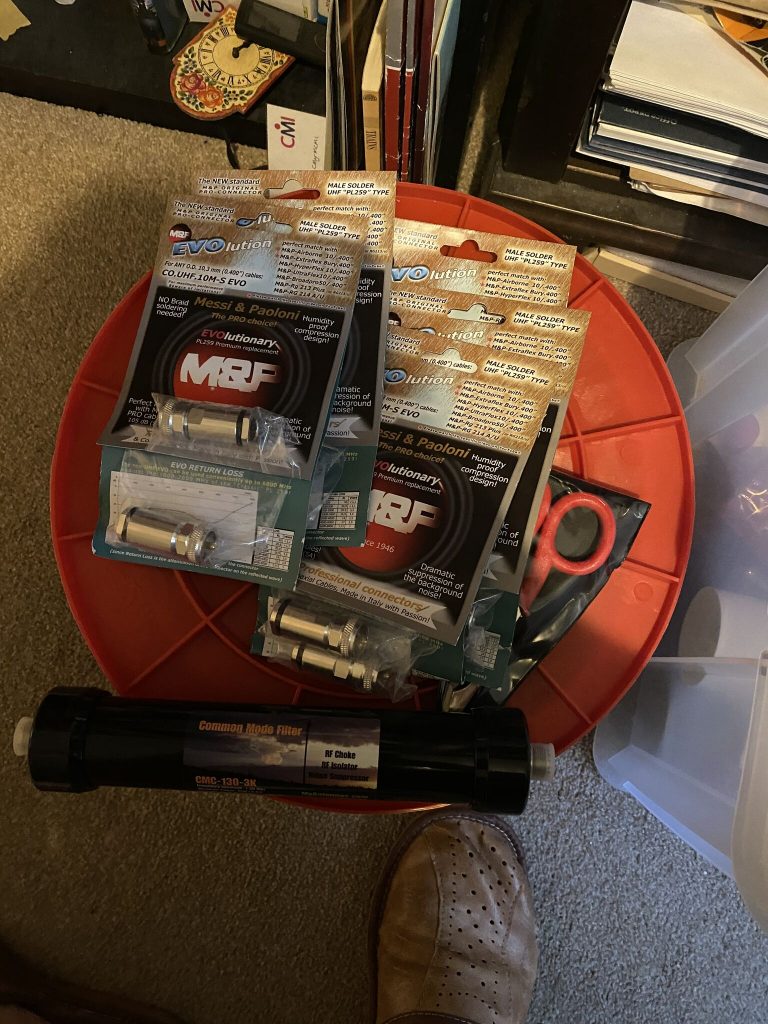
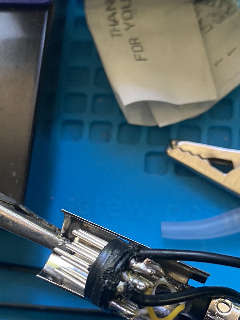
connectors and scissors
With that I have ordered and now received some UltraFlex 10 and connectors from W&S, plus the scissors to help me make a good job of it. There is this excellent video on how to put the connectors on the coax.
How to install M&P Connectors
Having received an email from M0MCX that the “Nebula” will be here any time soon I am naturally very excited to see how it all operates !
So in the QTH down in IO90 the met office issued their warning of bad weather. I brought my antennas down as a precaution of lightening strike. Following a couple of messages on the DX-Commander Discord channel the UK Antennas multiband end-fed was mentioned as a comparison. As such I’ve not had the time or opptunity to get it in place, and with the wire at 39 meters long would require some prep on how to get it in place !
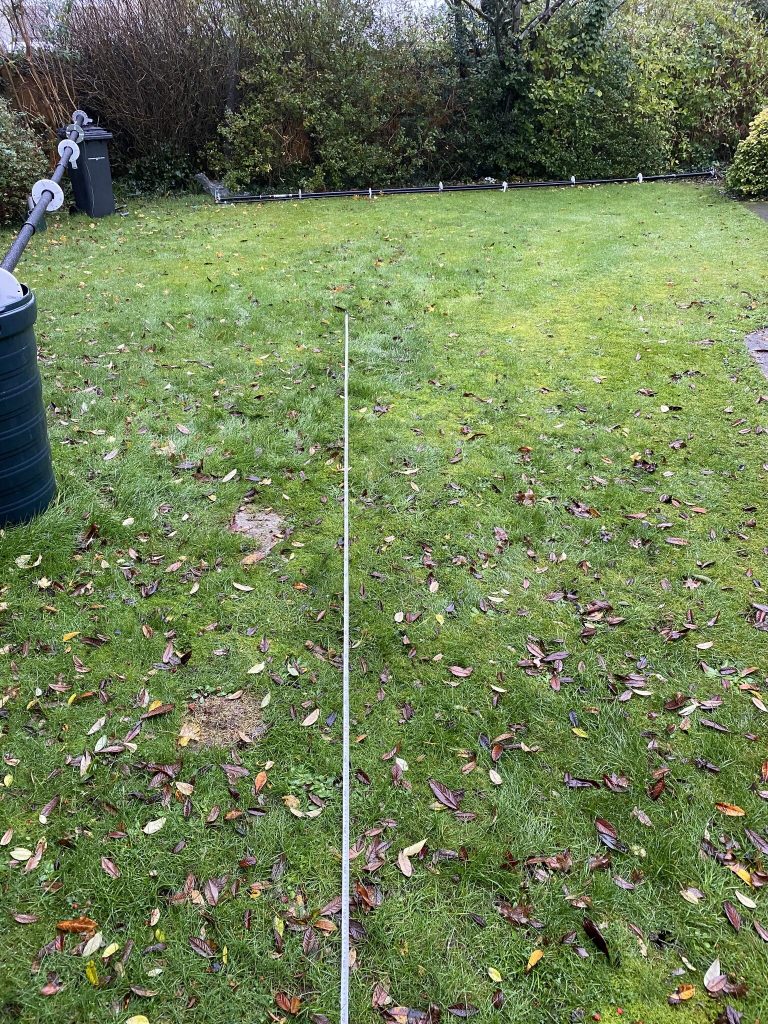
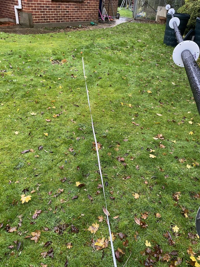
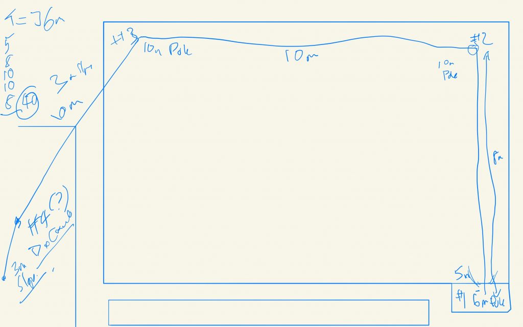
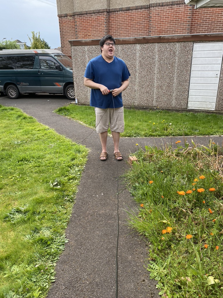
planning the long wire across the garden
The advantage of the DX Commanderj is that all the bands are vertical each, even 80m can be done lengthening the wire. With the End-fed finding how to route 36m of wire into the space I have was a challenge.
I have made a draft and took some measurements, and in combination with some sorta beam poless and mast, think I have a working configuration !
Will post as soon as the good weather has passed, really excited to try out a new antenna
So I’ve had a very busy week or two both on day-to-day 9-5 (+!) and around the shack.
I am lucky enough that I get a gardener once a month to do all the lawns and bushes, and I used the opportunity this time to take down all the antennas allowing for a very good tidy lawn.
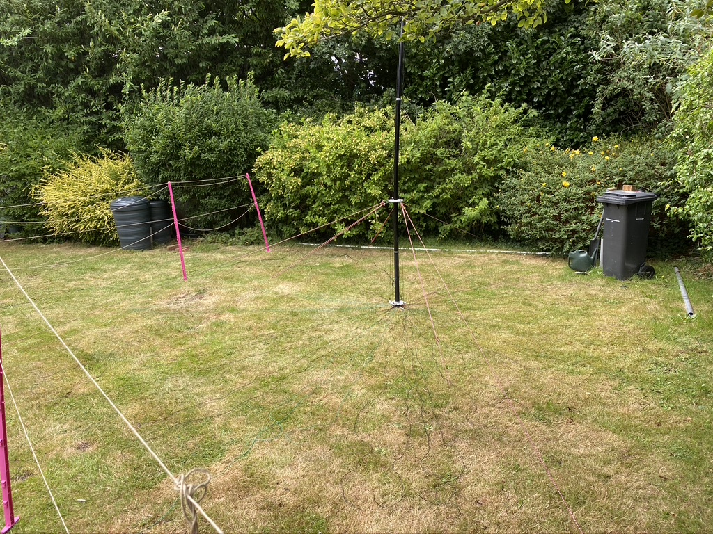
DX Commander #1 in place, very well guyed down due to the wind we are having of late
I also wanted to try out a method of increasing gain and reception using a 2 Element Parasitic Array on the 40m band – the youtube video here is really good at explaning how the setup works. I was already lucky enough to have another DX Commander on order before Calum goes on his holiday, so I set about measuring the distances and getting the 2nd DX Commander setup for just 40m
The main difference between a parasitic array is that its just for a single band and the distance between the two is 1/4 wavelength, in this case 10m. The wire *should* be a little lower on the 40m frequency than the ‘driven’ – but I am going to double check that when it comes to more fetteling (cant ever get an antenna too perfect imho !).
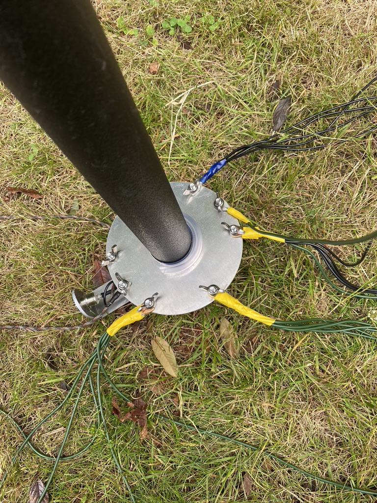
radials, still 4*5
that lovely wire
radials meet driven plate
parasitic 40m dx commander
As you can see in the pictures, I have followed Calum’s advice pretty much and put the radials down, doesnt matter on the 360, but the length is there for 40m. The main difference is that the radials are directly connected to the driven element plate and there is no physical wired connection between the two antennas. I did check the S.W.R. on 40m (and 15) and it was a more than acceptable 1.4:1 across the band *before* moving the radials up. (Note will be finding a cover for the SO239!)
I need to find a ‘good’ way on proving the parasitic is having the desired effect. Out of interest i did attach my rig master to it whilst transmitting WSPR on 40m and sure enough the SWR did go up, which does at least prove that its resonating a transmission on the right frequency.
In practice I gave trusty FT8 a go, and sure enough I was getting far more +db on the map than i have ever had. Now this isnt particuarly good ‘science’ as there could be so many reasons why that was happening, so i could of got lucky. But I will find (and if someone wants to add a comment please do !) on how to test the effectiveness (i’m expecting something like +3-5db gain) I’d be glad to accept it !
I have also upgraded my ‘main’ tranceiver, the reasons are multiple, but mostly the Icom 7300 got very good reviews and the price/performance balance looked amazing.
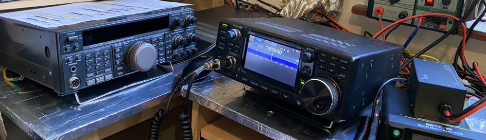
The Icom 7300 now in the shack
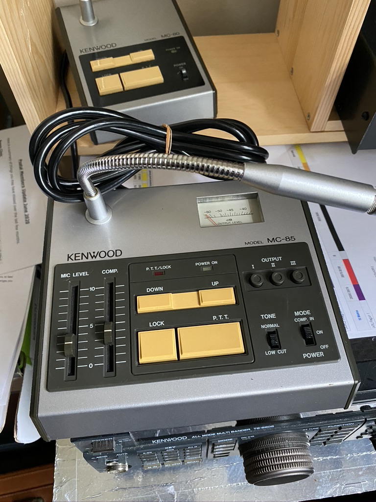
That is not to say that all the hard work and effort put into the Kenwood TS690-S will be wasted, absolutely not ! I have actually made another addition from Japan, this lovely microphone unit !
This pristine MC-85 came from Japan, sadly without box, but its immaculate !
I am hoping i can use the output switch between the Kenwood and Icom as this looks such a gorgeous microphone and the reviews of it are very promising.
I am going to put an end-fed multi bander on the TS-690S and having seen UK Antennas posted on the DX Commander Discord, done some research and went for it !
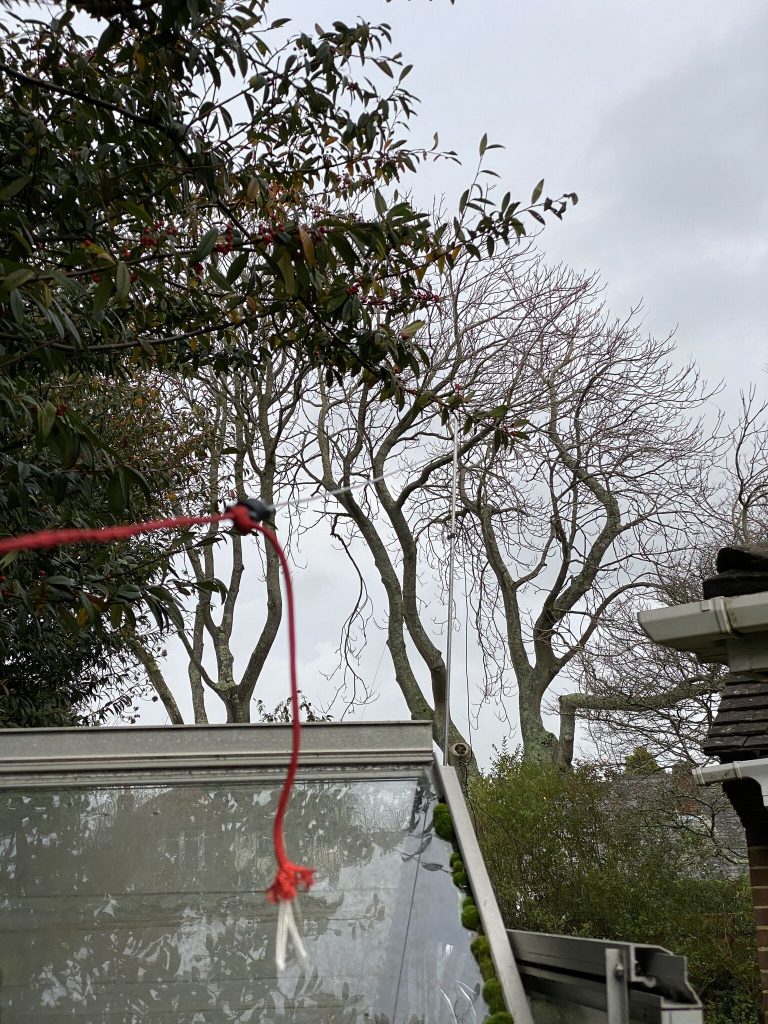
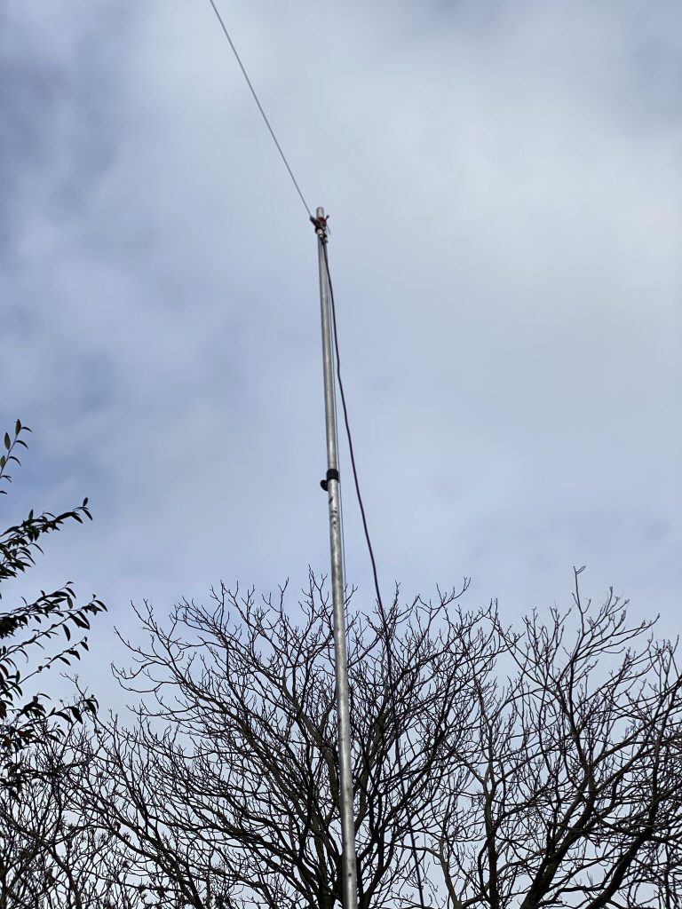
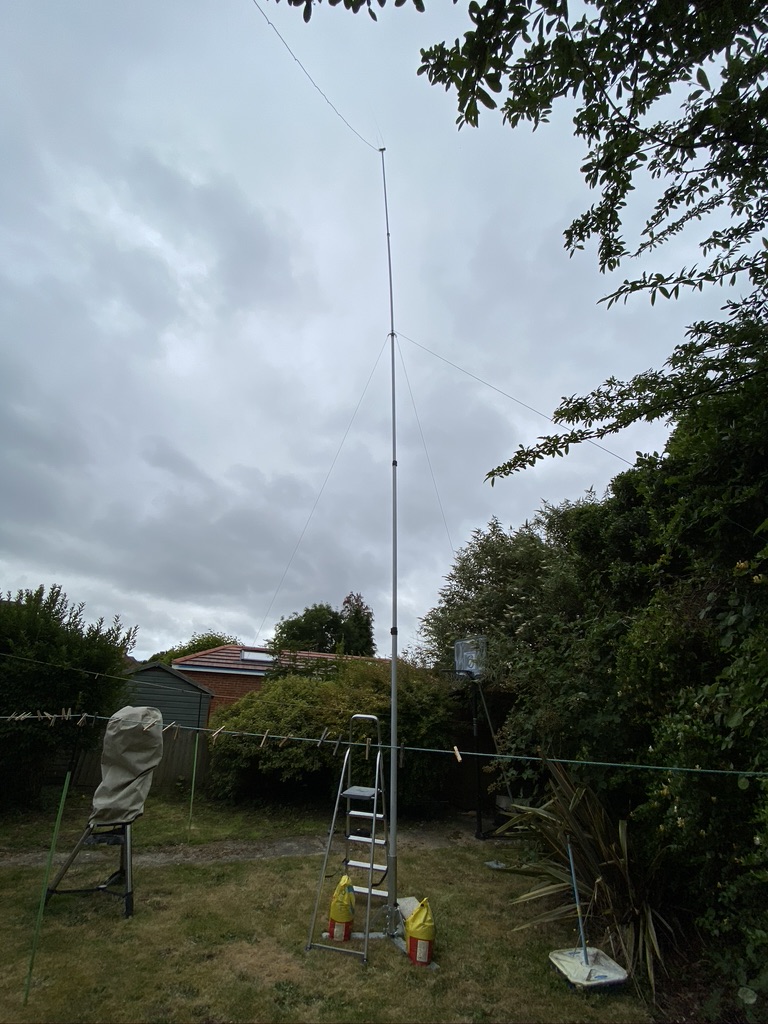
I have yet to install the antenna as I have moved my 2m/70cm mast to the rear garden. Putting out a big thanks to the after-sales support from Moonraker as I wanted to fully extended my 40ft antenna so i can use the 30m point as a ‘fulcrum’ for the end-fed antenna, creating a nice inverted ‘V’ to use.
Here is the mast I bought from them – the TMF-2 – it really is an amazing mast, yout get what you pay for with this. I looked at several sites, including this one on how to guy a mast. For 40ft it seemed i would need more guys – but gave the chaps at Moonraker a call to explain my mast, antenna and use, and re-located my guy-ring to a centre point on the sectional mast would be ok for a temporary antenna, with the obvious warnings for wind,etc.
I set about with my son (always good to have some help!) with getting the mast up and really well guyed in. I’m made up with the results, I’ve never seen the antenna looking so good and secure. The heavy duty base will be getting some additional ground-pegs but trust me that thing is HEAVY, its not going anywhere 🙂
40m mast with 2m/70cm J pole on top
I was able to reach all the local repeaters as before, but have yet to get a contact to check my signal report (such is VHF during the day time).
So there has been alot of change in the shack, but i’m really happy with the direction its going in !
bit of a longer post today so grab a cup of tea is recommend, else scroll through the page until you get to the bit you want to know about
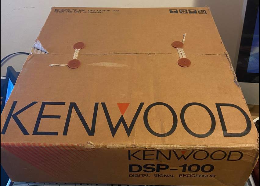
Several weeks ago I was browsing the local 2nd hand radio shop where my TS690 came from, and amazingly they had the DSP-100.
Kenwood DSP-100 – finding chicken teeth is easier
The DSP-100 is one of the first ever Digital Signal Processors. Kenwood were pretty ahead of the game when they released it. You will see all the filters and features you see in this unit in most modern transceivers, but this is (I guess) about 20+ years old, and are hard to come by. I dont mind saying this unit, 2nd hand was £333 ,which is only £40 different of what I paid for the TS690S, but what it brings to the radio is RF filtered and processed. The promise of ‘hi-fi’ quality SSB, AM, CW and RTTY was too good to pass up. And it looks gorgeous too 🙂
When I first set it up with my TS-690s I connected in my xggcomms Kenwood interface I started running into issues. I honestly believe this is no fault of the xggcomms device, but moreso on how the RS232 signal from the DSP-100 unit is processed and fed into the transceiver. Its fair to say whilst I was overjoyed in having the DSP, alot of what i do requires a good CAT connection to constantly adjust the frequency (FT8 & WSPR), so I reverted back to the Xggcomms interface only and started investigating.
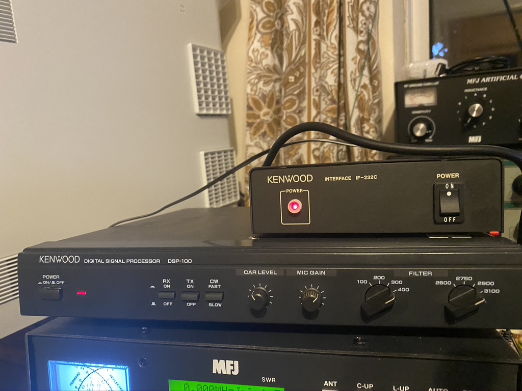
Upon searching, other people had experience similar, but not identical issues. The key to fix this was the IF-232C. This translates the serial input into signals at the correct levels for the DSP & the TS690s.
Up until now I have been using a laptop, which had become increasingly over burdened with USB dongles/hubs coming out of it, also getting the computer to be ‘RF Friendly’ and grounded proved a challenge. The only way i could see to easily and reliably RF was via the USB port, and this little lenovo laptop computer already had *alot* coming out of the USB ports.
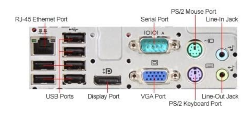
With that I decided to get a dedicated full-size ham-radio PC. Nothing expensive or new, in fact I was looking for ‘older’ models with a native DB9 Serial interface so USB to Serial issues would no longer be a problem. This HP Elite 8200 met the specification needs for what I would be using the computer for and was a reasonable price/availablity. I could add all the audio inputs and outputs to the native connectors and also use the on-board serial (or so he thought…)
HP Elite ports – native Serial Port and audio on-board
Having migrated PC i went about installing first the apps I know, namely Fl Digi and FL Rig. I have been using these for sometime for WeFax and love getting the images in. The good thing about reducing the QRM, i can visually see it has been reduced, as I will show later.
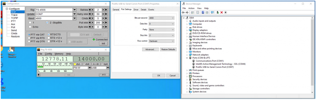
I did run into some issues with communicating with the PC, the Serial Port settings had to be changed on the PC also, by now I had also discovered i had ordered the wrong cable from RS Electronics, but have a replacement on the way. I went back to using a USB to RS232C interface for now, which after some tweaking worked. I’m sure I’m not the only person who would still setup a IF-232C, so here are the settings I used between my PC and the RS232C.
Screenshot of Windows PC Running Windows 10 and USB Prolific based RS232 connector
Incase its hard to read on the screen, heres the tabulated form
Setting
Value
Bits Per Second
4800
Data Bits
8
Parity
None
Stop Bits
2
Flow Control
Hardware
Advanced
Leave FIFO Buffers at max and on
Table of Settings for the RS232 Port on Windows for Kenwood TS690S and IF232C
In the FL Rig for the Serial port the settings are as follows (Select TS450S as the transceiver) :-
Setting
Value
Baud
4800
2-StopBits
Enabled
PTT via CAT
Enabled
RTS/CTS
Enabled
Retries..Byte intv
Defaults
Init (Click)
Connected
FLRig Settings
Kenwood DSP-100 with the IF-232C
Now I dont mind saying that I’m still learning, so understanding what filter to use when is very much a case of ‘try it and see’, but i will show a comparison between before I started all the QRM clean up and the acculmation of what I have done so far *plus* the use of the DSP-100.
WeFAX – local QRM is quite clear with the ‘banding’ visible across the otherwise clear image
As you can see in the above image, there is alot of QRM in the picture, the ‘banding’ consistant across the image, in this case probably caused by the Ethernet over Power adaptors, is very clear.
Here is a scan today, same antenna, but will all the additonal work to reduce QRM and the DSP in Receive mode filtering.
Reduced QRM, what you do see is from a fan running because its hot today 🙂
When less electical items in the house are running, namely fans, washing machines and the like here is an example image. Again, this is the same antenna, same external line filters/chokes and the DSP and recent QRM work outcome.
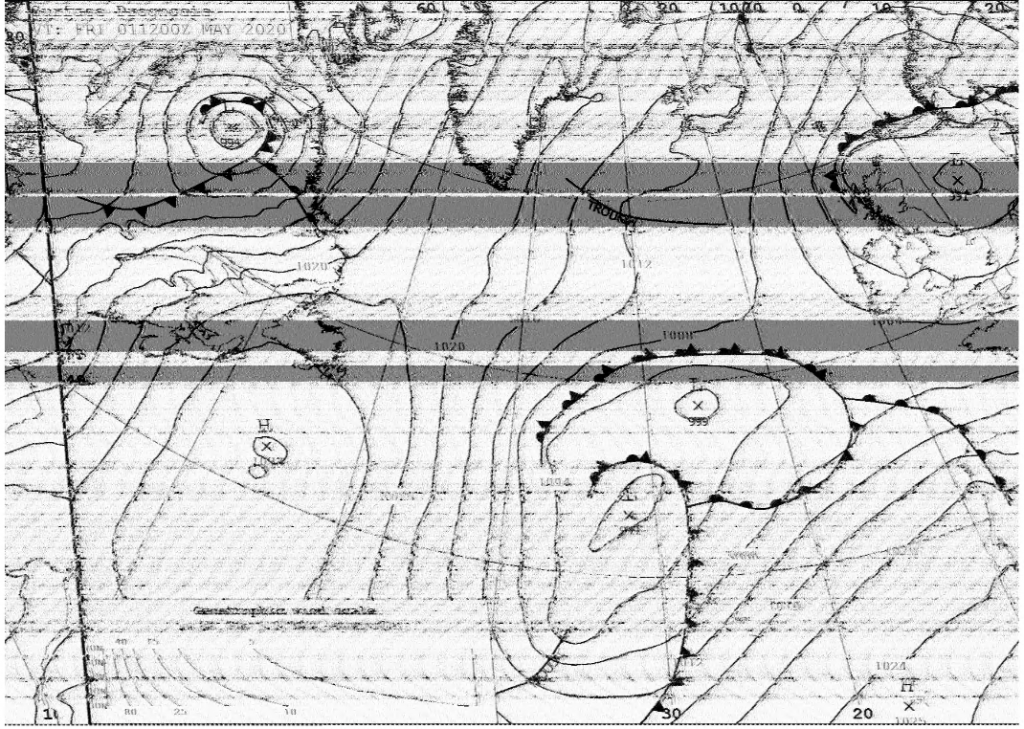
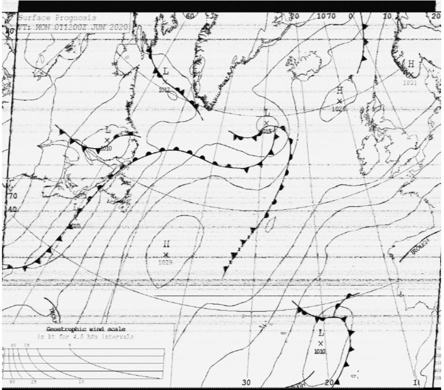
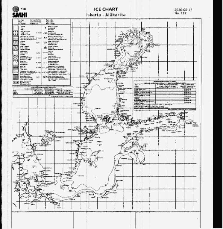
The ice-chart from Hamburg
The ice-chart from Hamburg is the equivlant for me as the last row on the eye-test exam. The letters on it are incredbly small and the details/dots equally so. Whilst with a zoom there is some slight distortion (so more to be gained!) there is a total absence of the QRM which was so present in the first WeFax image shown.
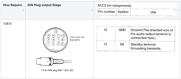
I am adding a MFJ-1026 to the mix now (Thank you Nevada radios, you are doing a great job during the lockdown !) and I cannot thank Steve from Xggcomms enough for the assistance he has given me. I asked Steve for some help on how would I go about connecting both the xggcomms and mfj-1026 at the same time, as they need access to the T/R Control line present on the ACC-2 port. Sure enough Steve was good enough to reply on how to do this, by way of opening up the connector and adding a connection to pin 13 and ground (I used pin 12 for ground).
From Page 22 of the TS690S user manual
I had recently performed an inventory of all the wires/cables,etc I had, so it was easy to find the phono socket I required to connect the back of the MFJ-1026 phono socket to the ACC2 DIN plug.
I first tested the connectivity between socket and plug, to ensure it would work correcly before opening up the xggcomms. I am generally unhappy about opening working equipment in that I could break it and make it unoperational, but as Steve had already offered his support should anything go wrong, i bit the bullet and went for it. Needless to say, it wasnt an easy job for me who doesnt do this type of soldering reguarly.
xggcomms intact
removing the flexible case allowed easy access
respect for that soldering
this is going to be interesting..
pin 13 & 12…
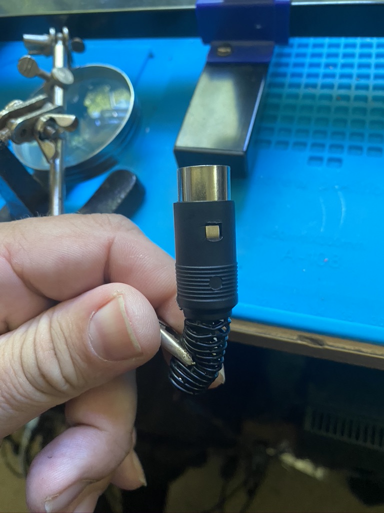
there they are…
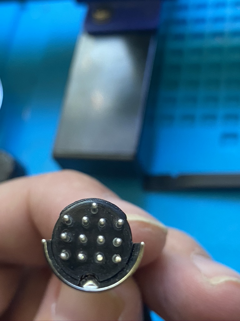
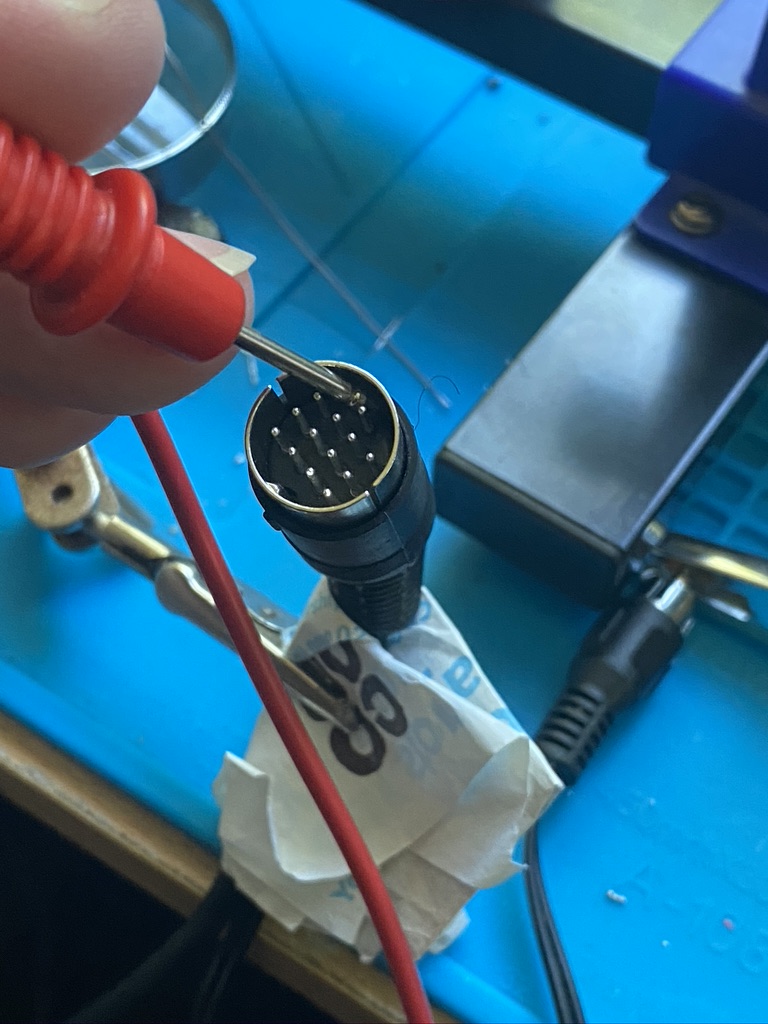
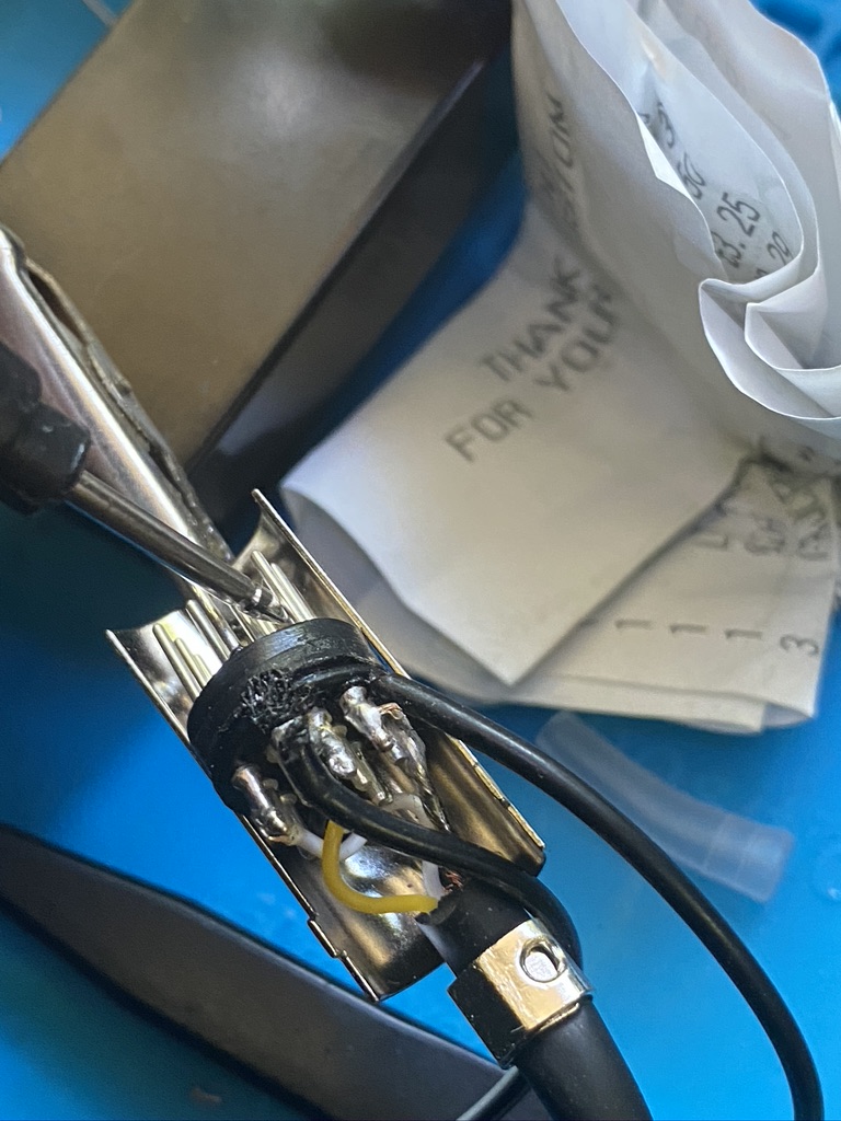
Examining the DIN socket before modification
I had already pre-tinned and checked the continuity between socket and wire on the phono socket, so was confident that as long as I was careful I would be able to add the necessary wires to the respective pins.
a good start
nice on the earth
crock clip on shielding
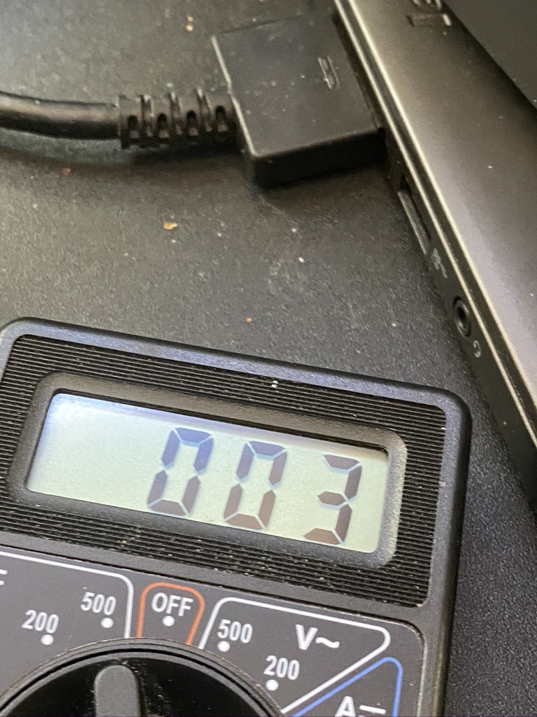
pin 13 result
pin 13 checking
phono live pin
another nice result
soldering was a challenge
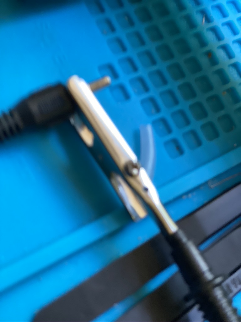
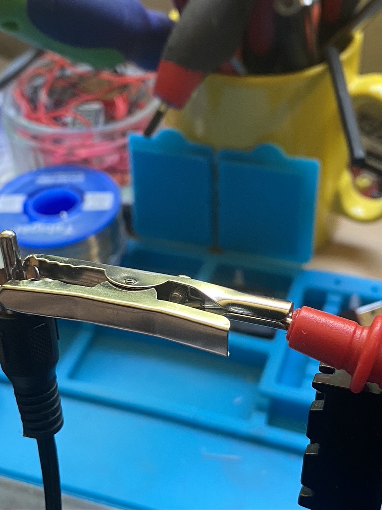
using a croc-clip helped the measurements
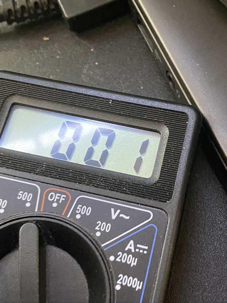
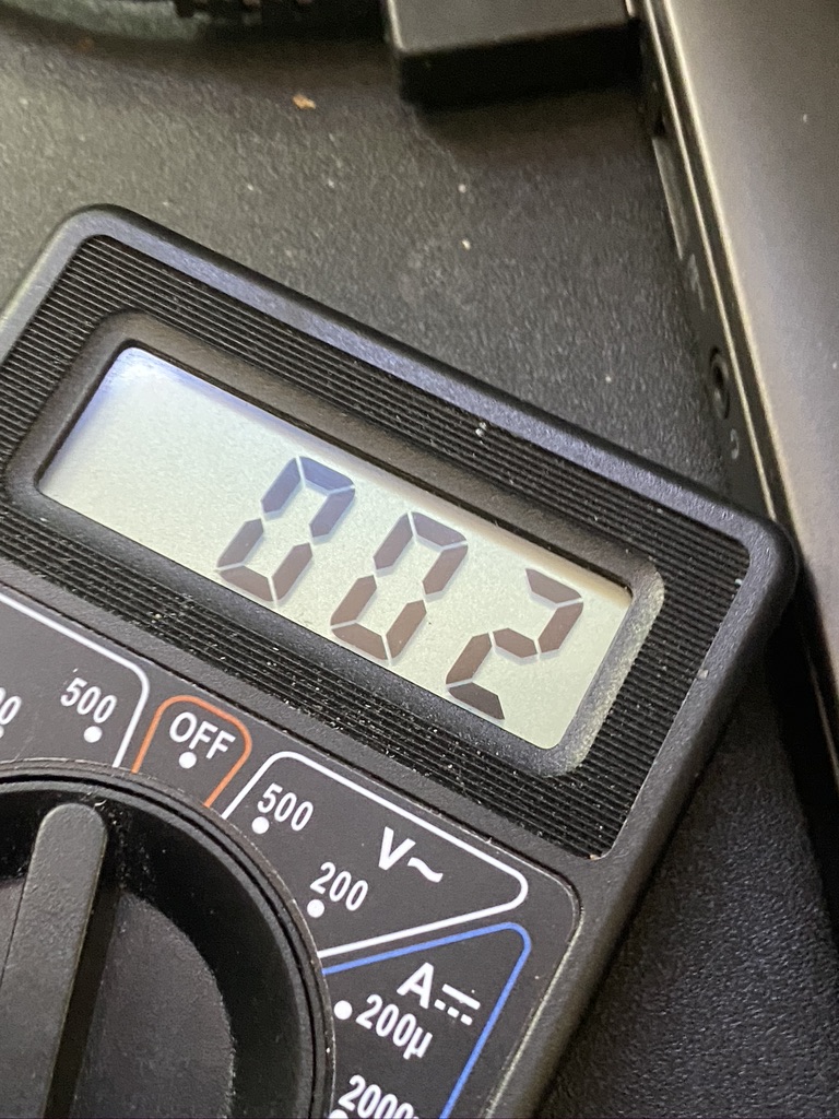
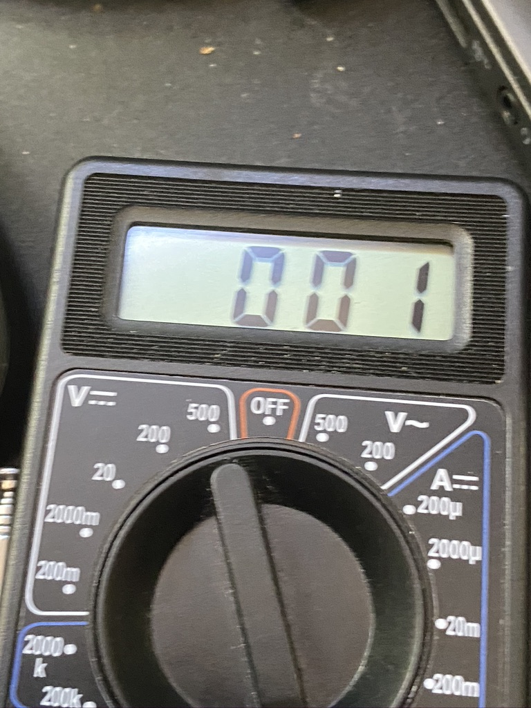
down to 001 with a better fit of testing equipment
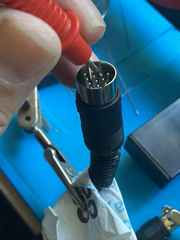
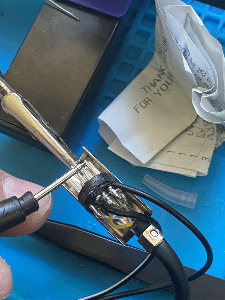
ensuring the pins are level and connected
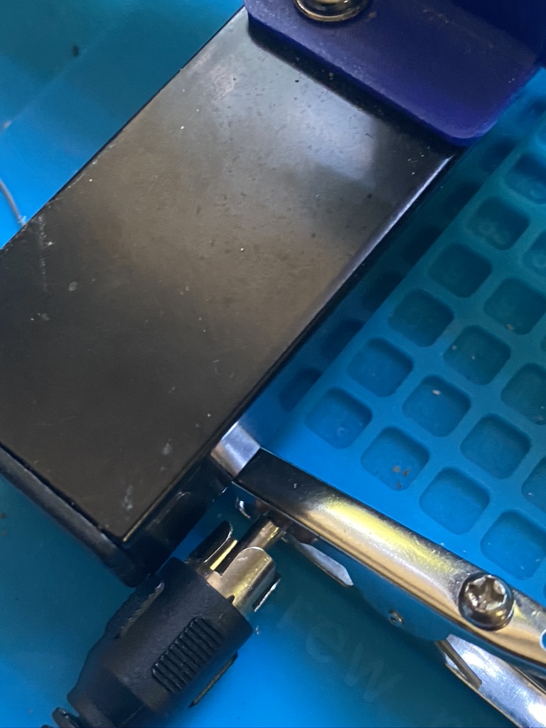
‘live’ socket
testing for no interference, result!
Adding pins 13 and 12
I dont mind saying that upon putting the shielding on and checking before plugging in that i found that the case (which should be grounded/seperate) ended up being ‘shorted’ and no resistance was shown on the voltmeter. Undeterred I undone the case and carefully applied a small piece of masking tape across the top pins ‘tucking’ between pins to give some isolation. I apologize i didnt take a picture of this. This had the required effect and that when the casing and flexible connector were restored, the isolation between pins had been restored.
Having completed the cable, the next step is to install an external auxiliary antenna for the MFJ-1028 to match against. I considered several ideas, as in just using a simple end-fed piece of wire, to a range of ‘small’ antennas from Russia that attracted QRM to be used in this way. In the end I decided to get another DX Commander. Whilst I wont totally multi-band this will all 6 elements (in particular 80m requires alot of space) I can setup the 2nd vertical ‘auxiliary’ about 2~3 meters from the ‘transmit’. With this I should be able to ‘phase out’ both any local QRM as well as distant QRM meaning I should not only be able to get out more cleanly, i should also be able to hear and filter those very feint remote signals that currently sit ‘below’ the noise table.
As ever, I will keep posting with my battle with QRM, which I think I am winning one week at a time.
Was browsing my youtube recommendations when I saw Calum was live streaming, tuned in and could hear everyone, which was really amazing to hear Calum and everyone else coming out the radio live.
Calum was ace in putting out some calls for M7’s – given the amount of people that call into his CQ’s, it was so nice that there was a gap for us on lower power (10W) to try and have a QSO.
I put in my call and Cal took his time, but i was just too quiet, see the video below.
https://youtu.be/1_jMJL7WLJ0?t=3932
A very faint M7ALU
Listening i can barely hear my voice, with M7 being just about audiable and i can recognize the gaps of how i would say ‘Alpha Lima Uniform’. Its a shame i couldnt get on the log book, but nethertheless provided a very exciting and good evening enjoying Calum and using the DX Commander as well.
Hopefully the restrictions on exams will soon be lifted and the extra wattage will help me get out that bit more. Fingers crossed !
The DX Commander comes with 100m of very good wire, which is enough for making the 4 element (40,30,20,17m) vertical and some for radials. Having already bought 50 meters of wire for 80m I was still down on the count for both radials and the ‘all band’ – having complete the ‘all-band’ construction it was now time to sort the radials !
With the orignial wire and radials I had around 28-30 radials, which whilst much better than only 1 and improvement on 15, is still slighty short for 80m and also more radials=higher Db out at other wave lengths.
So what is the science about radials ? The Calum has a good video to help, and the references are very good, so I’ll put that here first.
https://www.youtube.com/watch?v=qVG1jevrXaI
Radial videos from Calum
So basically adding radials helps (I did try to find a video of a person fallilng off a boat getting onto a pier, but was getting to distracted…) I took 50 meters of wire (the same type I had use on the verticals) and set about making into 3.5 meter lengths, which some great help from my son Paul which saved my back alot in terms of getting up and measuring and cutting !
pull and cut thanks Paul 🙂
it started as 50m, it became radials
cutting radials
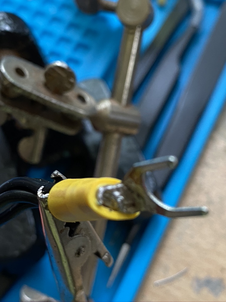
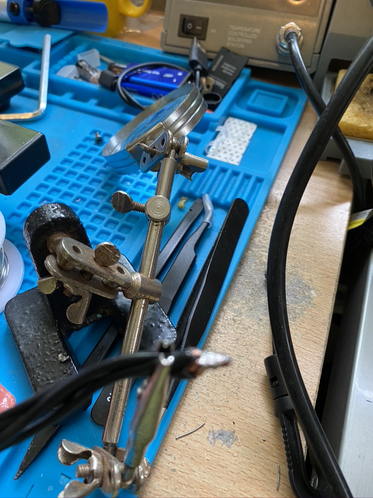
With the cutting done, it was time to return indoors for strip, crimp and solder !
new crimper doing a grand job
solder together, solder the crimp
strip, crimp and solder (*2)
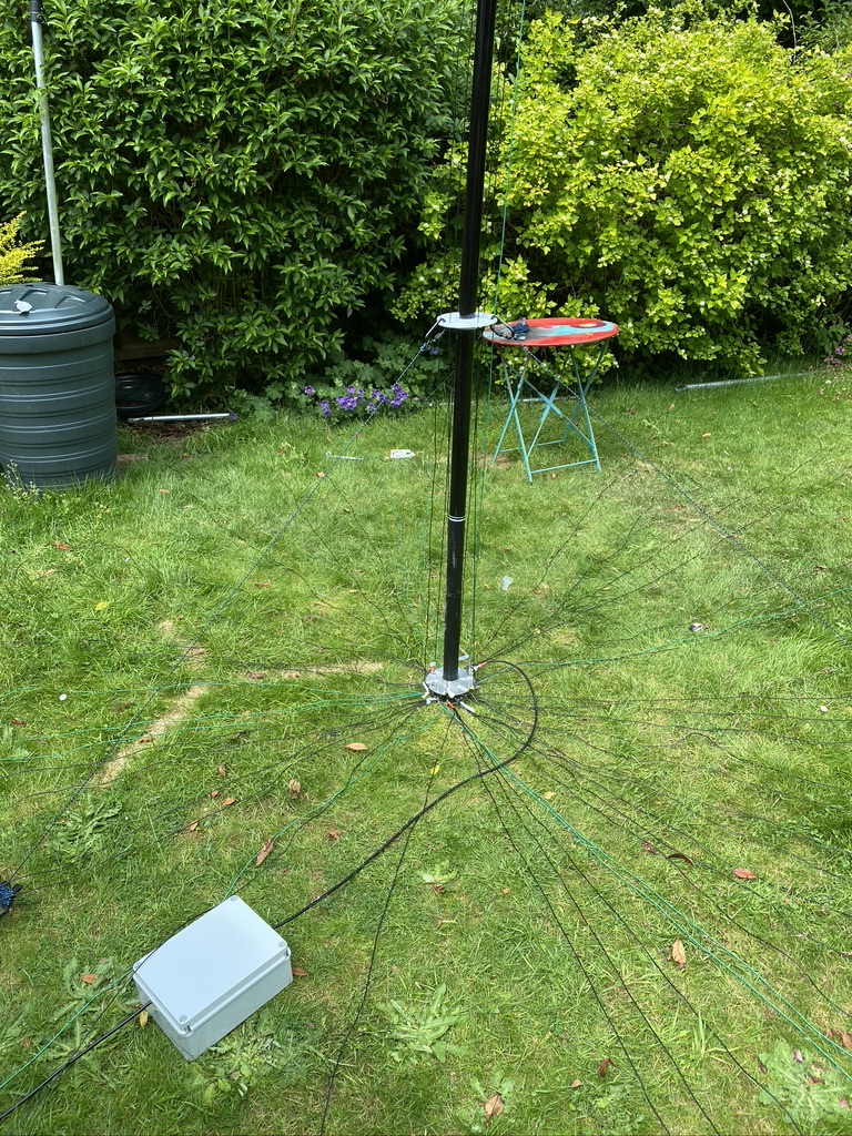
I then returned outdoors to install the addtional elements. I doubled up on one existing element, but had a pretty decent fan of 3.5m wire elements going on now.
a nice spread
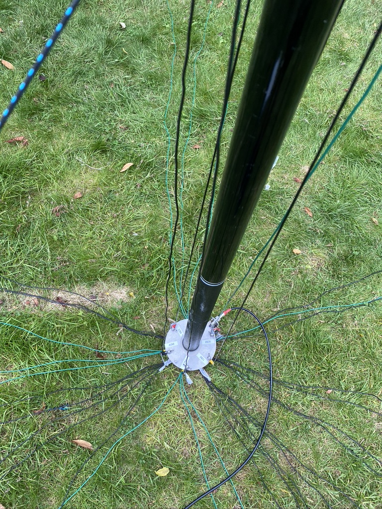
view from the base
keeping it tidy
gaps to fill
now with added elements
adding elements
I’d need to an exact recount (will do so later) but I think I now have enough radials to accomodate the 80m vertical.
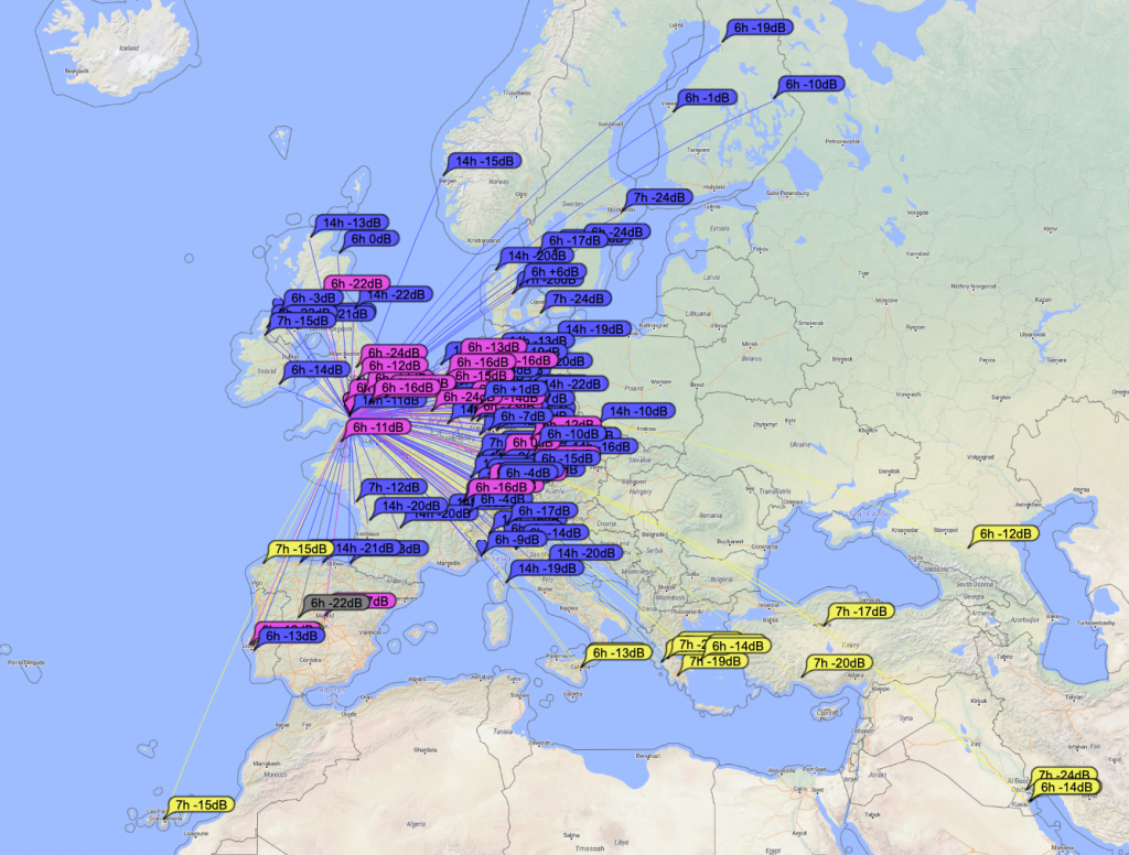
With having added the radials it was time to test ! For this I use FT8 as it has a great map and includes a signal report when a QSO is complete.
Reaching Kuwait on 17m
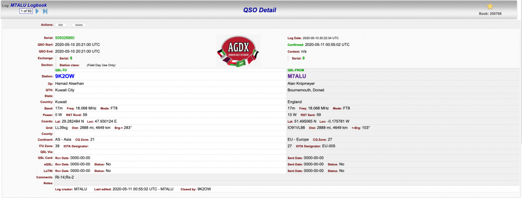
I was now reaching Kuwait on 17M and even better was that I could see the call sign in my WSJTX screen – i had to give it a try ! And sure enough within a few minutes (this guy was was getting alot of QSO’s in) I had made contact !
Contact with 9K2OW in Kuwait – a staggering 2,888 miles on 10 Watts of power !
So i think i could continue to add more radials, but for now I’m happy with how the DX Commander is performing and the radials are performing their function. I will investigate more ‘science’ based ways of radial performance, but his helps for now !