Was browsing my youtube recommendations when I saw Calum was live streaming, tuned in and could hear everyone, which was really amazing to hear Calum and everyone else coming out the radio live.
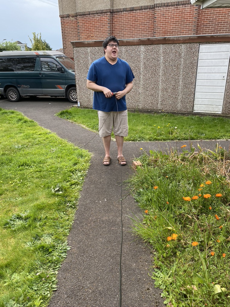
Calum was ace in putting out some calls for M7’s – given the amount of people that call into his CQ’s, it was so nice that there was a gap for us on lower power (10W) to try and have a QSO.
I put in my call and Cal took his time, but i was just too quiet, see the video below.
https://youtu.be/1_jMJL7WLJ0?t=3932
A very faint M7ALU
Listening i can barely hear my voice, with M7 being just about audiable and i can recognize the gaps of how i would say ‘Alpha Lima Uniform’. Its a shame i couldnt get on the log book, but nethertheless provided a very exciting and good evening enjoying Calum and using the DX Commander as well.
Hopefully the restrictions on exams will soon be lifted and the extra wattage will help me get out that bit more. Fingers crossed !
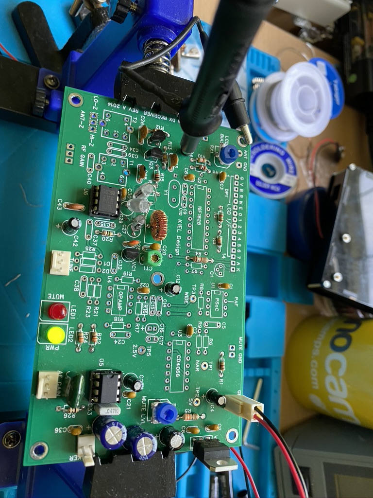
So having got the lab somewhat tidy (pics and a full reveal will come soon !) i can continue working on my 40m Receiver Kit – having wound the toroid and secured it previously, the next step was to add the components and buffer around the tuning circuit.
I would like to point out (maybe again) that one thing that i think is very much missing from this kit is a schematic of the ‘blocks’ of the decoder. At this stage it would be very much helpful to understand what components and how the modules worked together, in particular when we get to the stage of the ‘decoder’.
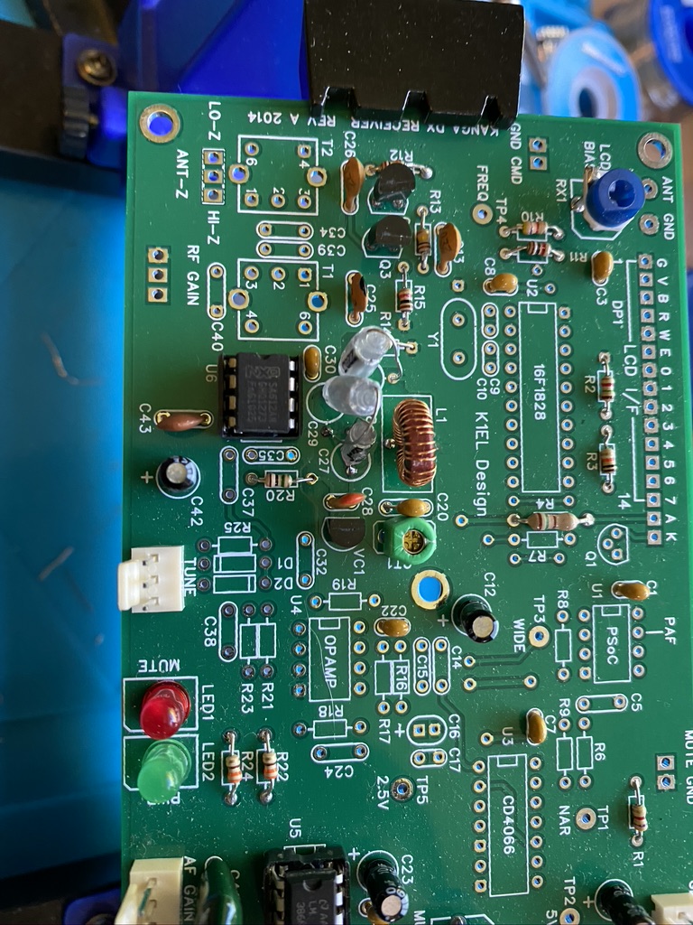
Capactors, IC’s and variactor Diode !
I found getting most components on the ‘push-thru’ was easy enough, the only components which presented a ‘challenge were the NPO and Polystyrene capacitors. As you can see the round circles for C27,C28 and C30 are ’round’ enough when the capactiors are verticle.
Capacitor mounting
On the first attempt i tried the ‘test’ method of using a radio tuned to 7Mhz and got nothing at all. It also didnt help that I didnt know what i would be looking, or in this case listening for. I took a break and came back to it the next day.
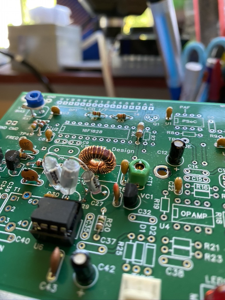
visually looks fine, but actally a dry join on the trim.
Tracing my work I found that i had left a slight dry join on the trimmer. As i have now aquired an oscilliscope I thought it was the perfect use to find the frequency and adjust it.
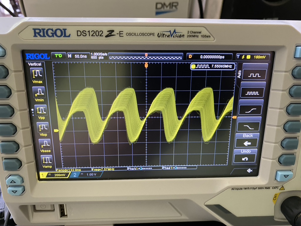
We have a 7.5Mhz frequency!
I was so happy to even see a signal on the oscilliscope and also the read on the frequency was not so far out from the 7Mhz. I was lucky enough that the oscilliscope probes come with tuning screwdrivers which are the ‘safe’ type required to tune the trim. I set about tuning to 7Mhz !
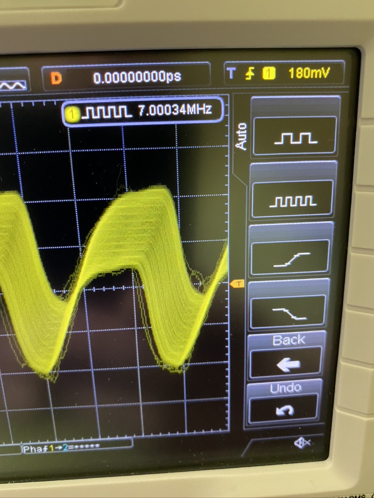
Close to 7Mhz
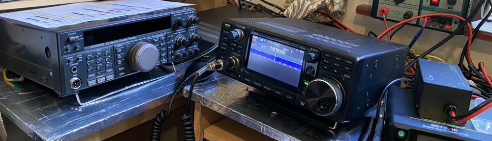
On the scope i could the frequency to read between 6.90nnn and 7.000nn. I thought about trying to see if I could hear anything on my handheld standard (AM) and my transceiver which has more modes (including CW & PSK) as well as specific filters.
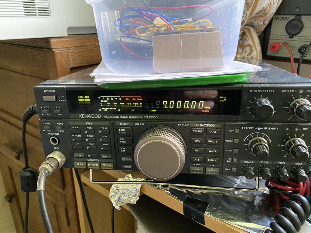
7Mhz = beeep
I was very happy to pick up a clear signal on 7Mhz. What was interesting also was that where i have the probe into the VFO / Decoder board, it had turned the ‘wire’ into a small resonant circuit – in fact I could turn my VFO into a theramin ! After 15 minutes of playing wooping noises I set about completing/and tidying the kit up.
I’m really glad that the receiver is going so well – its been all the work I thought it would be but its now very satisifying, esp as its gets more complex.
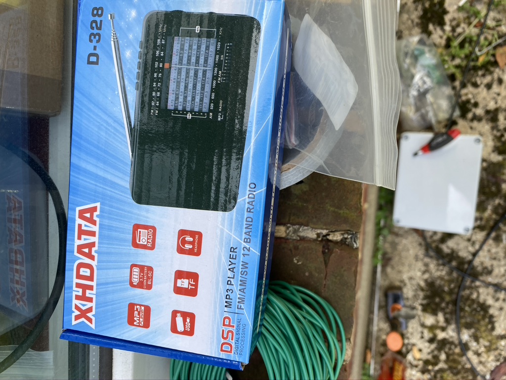
So last night (11/5 – 12/5) Turned into a bit of a QRM mission. Not exactly sure how, but found myself really getting trying to find the source of a specific hum, as I am gradually reducingt the amount of interference/QRM I am picking up. I started with taking my little AM radio (D-328) around the house buzzing very present. What I wanted to rule out was the utilitys nearby and the garage. Being 1AM and wandering around with a pocket radio should make for amusing footage on the overnight security video from the garage today 🙂 Anyhow, I could pick none up.
I returned home,sure enough the ‘buzz’ was back. So as it was quiet in the house (trust me, we are 24/7 shop here!) i started going thru the fuse box, its an older one, but still thankfully a trip/RCD (?) type box where I can easily flip the circuits. Sadly the circuits are not labelled, which I find quite unprofessional, apart from the ‘light’ fuse. I started flipping fuses and on the 5th one the buzzing on the radio stopped, as did all the mains power to my study and I think the front part of the house.
I set about unplugging everything in my study with the mains back on, hum still there. So I started to research/googling hum between 50 and 500Khz – it seemed so precise, I figured it must be some form of ‘man made’ interferance.
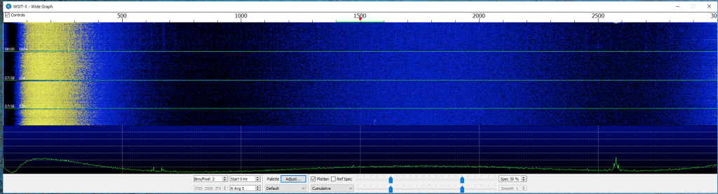
Here is a video of what it sounds like :-
So you can hear it all the way up from 50kHz to a very loud abrupt end at 500kHz. I set about googling as to what that could be, and sure enough found th GM4FVM page on ‘power line adaptors’. I’ve been very careful to remove and limit the use of ethernet in the house now, so suprised that this had caught me out. I immediatly removed the BT Ethernet over Power adaptors I had. This is the result
A longer video with manual AM tuning and a ‘sweep’ of USB
If you are patient enough to have watched the whole video, i congratulate you 🙂 But you can hear the big difference between what a power line adaptor can do to HF/RF in a shack, i.e. completely destroy all but the strongest signals.
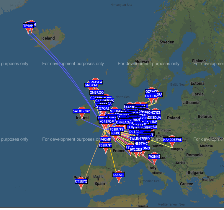
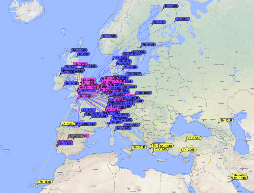
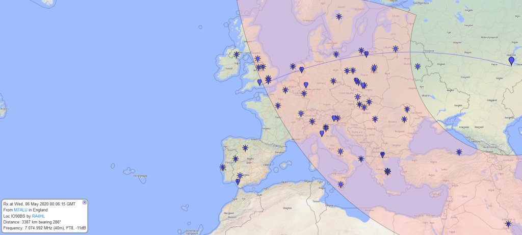
This morning I tried out WSPR, the results on receive and transmit speak for themselves :-
wspr map is somewhat busier…
So now its time for work but I think i have taken another big step in reducing QRM in my shack
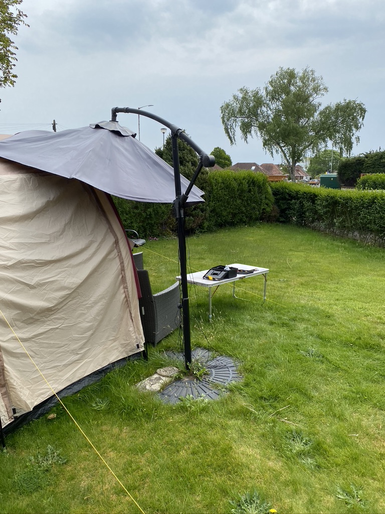
The DX Commander comes with 100m of very good wire, which is enough for making the 4 element (40,30,20,17m) vertical and some for radials. Having already bought 50 meters of wire for 80m I was still down on the count for both radials and the ‘all band’ – having complete the ‘all-band’ construction it was now time to sort the radials !
With the orignial wire and radials I had around 28-30 radials, which whilst much better than only 1 and improvement on 15, is still slighty short for 80m and also more radials=higher Db out at other wave lengths.
So what is the science about radials ? The Calum has a good video to help, and the references are very good, so I’ll put that here first.
https://www.youtube.com/watch?v=qVG1jevrXaI
Radial videos from Calum
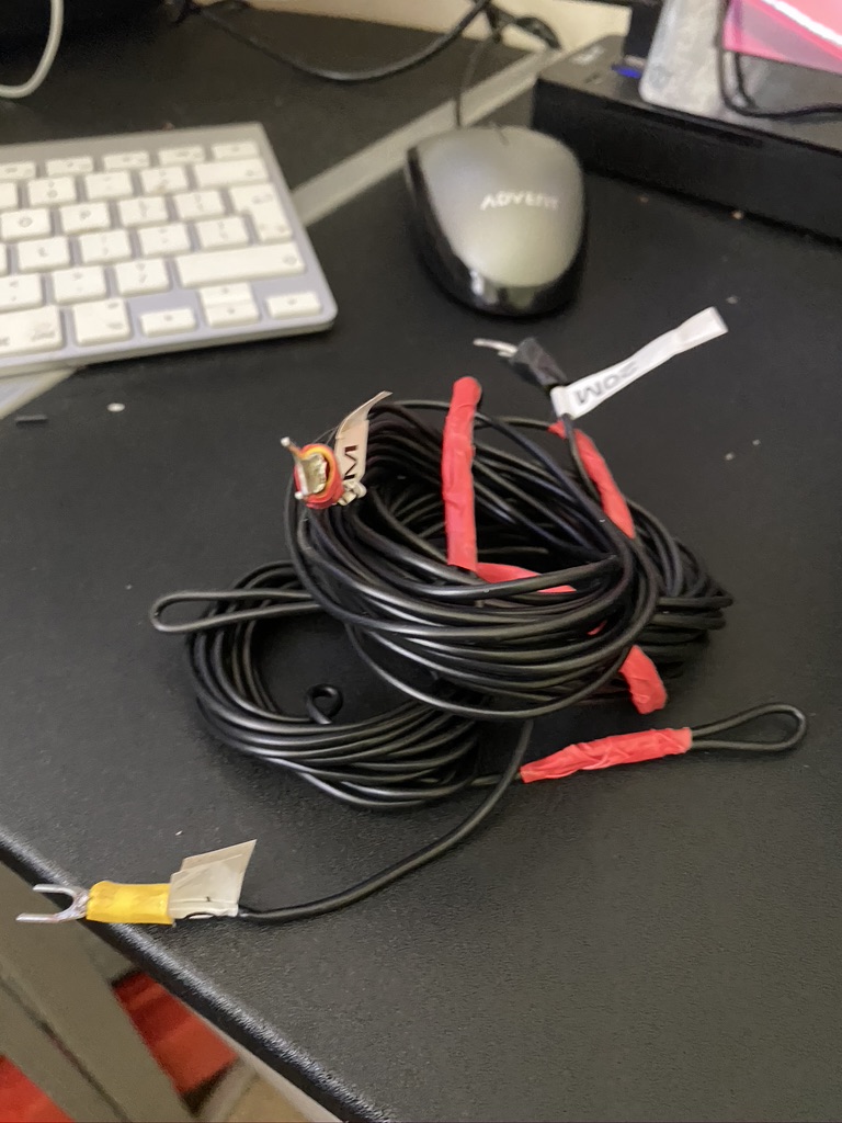
So basically adding radials helps (I did try to find a video of a person fallilng off a boat getting onto a pier, but was getting to distracted…) I took 50 meters of wire (the same type I had use on the verticals) and set about making into 3.5 meter lengths, which some great help from my son Paul which saved my back alot in terms of getting up and measuring and cutting !
pull and cut thanks Paul 🙂
it started as 50m, it became radials
cutting radials
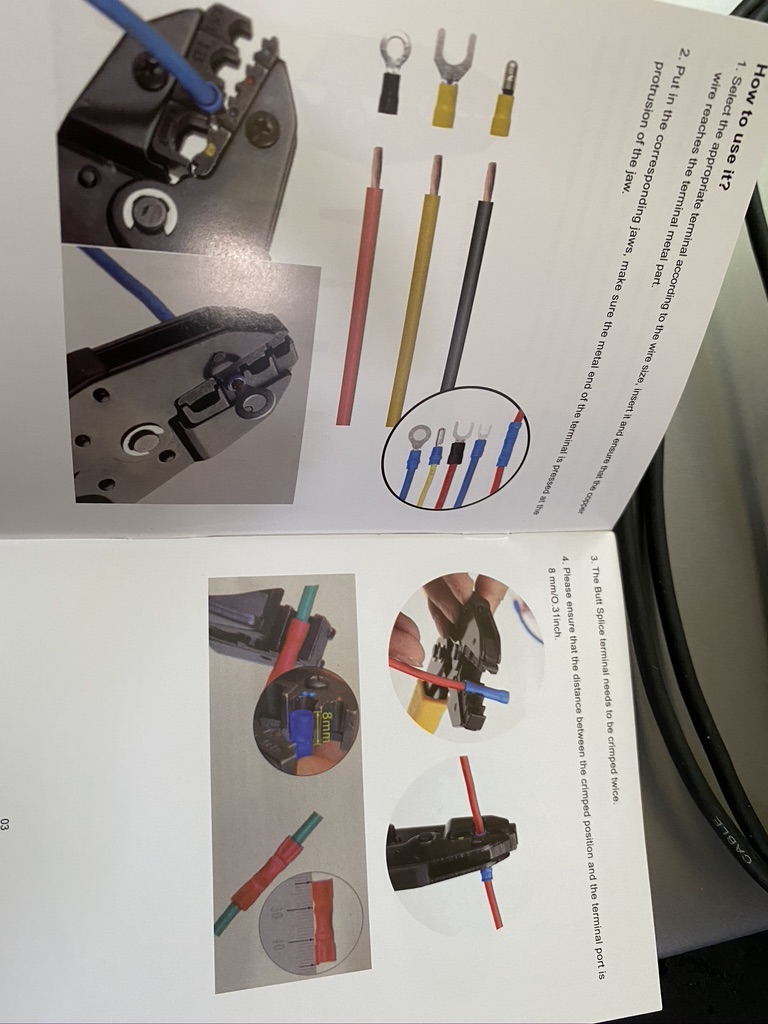
With the cutting done, it was time to return indoors for strip, crimp and solder !
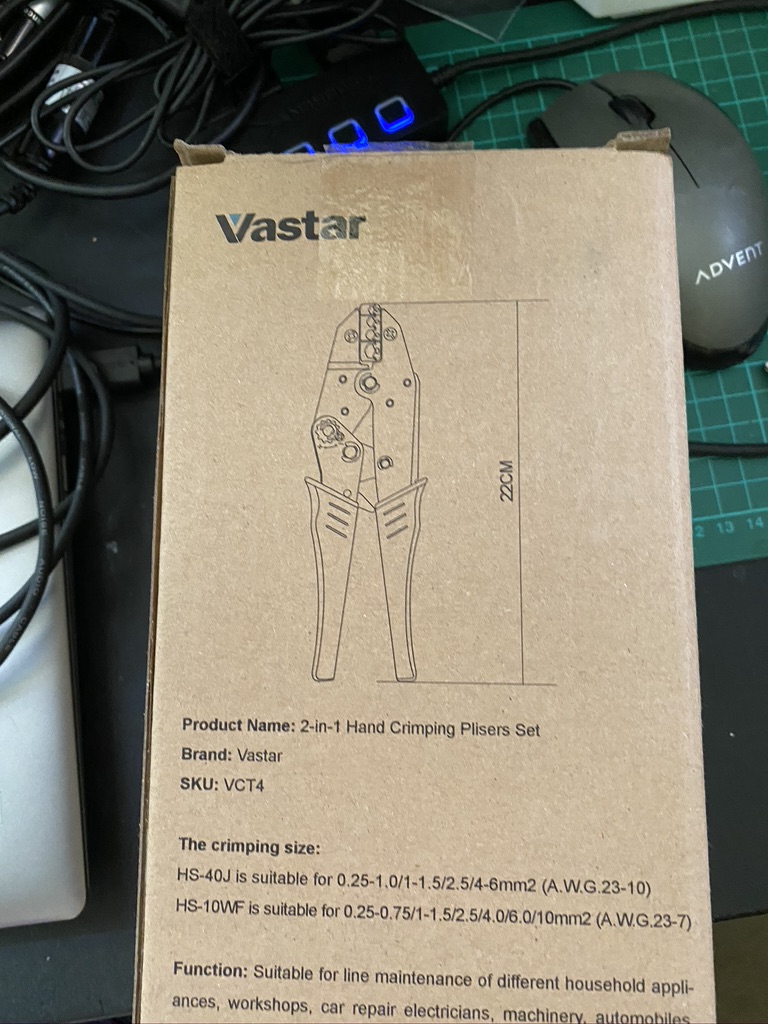
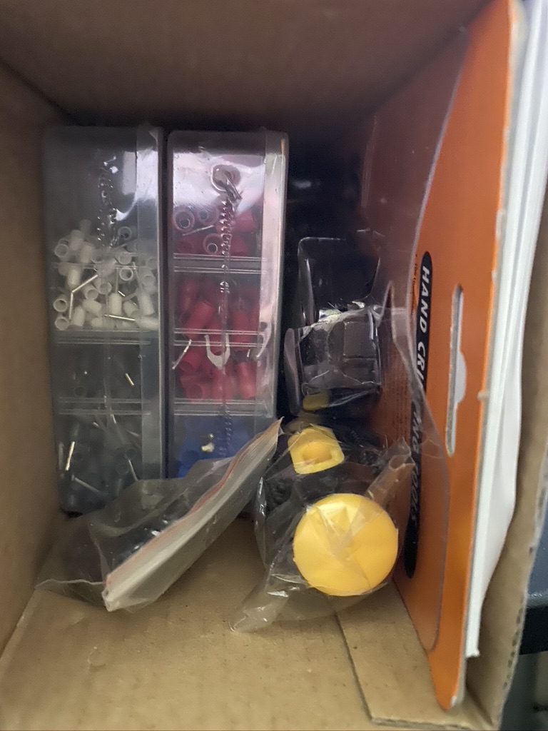
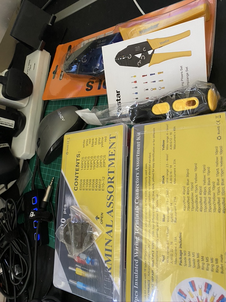
new crimper doing a grand job
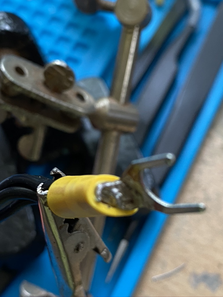
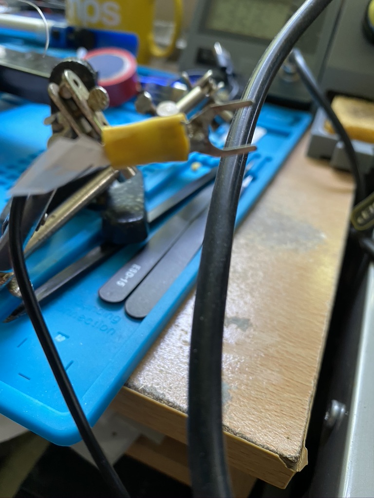
solder together, solder the crimp
strip, crimp and solder (*2)
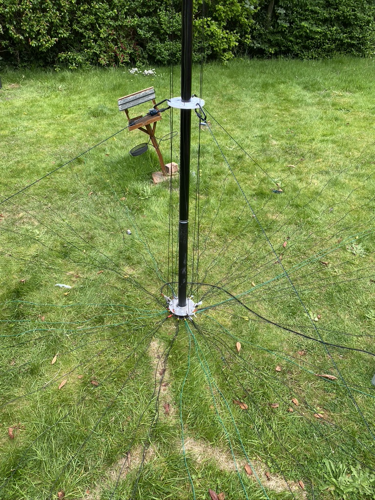
I then returned outdoors to install the addtional elements. I doubled up on one existing element, but had a pretty decent fan of 3.5m wire elements going on now.
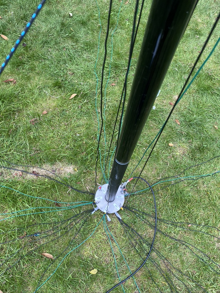
a nice spread
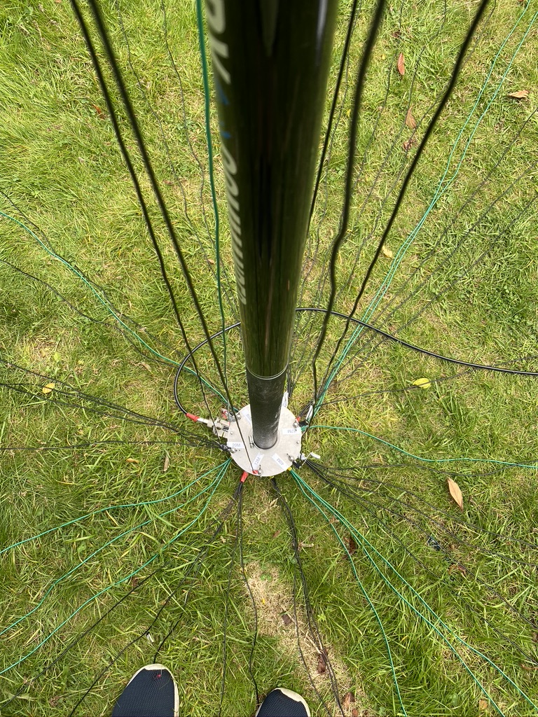
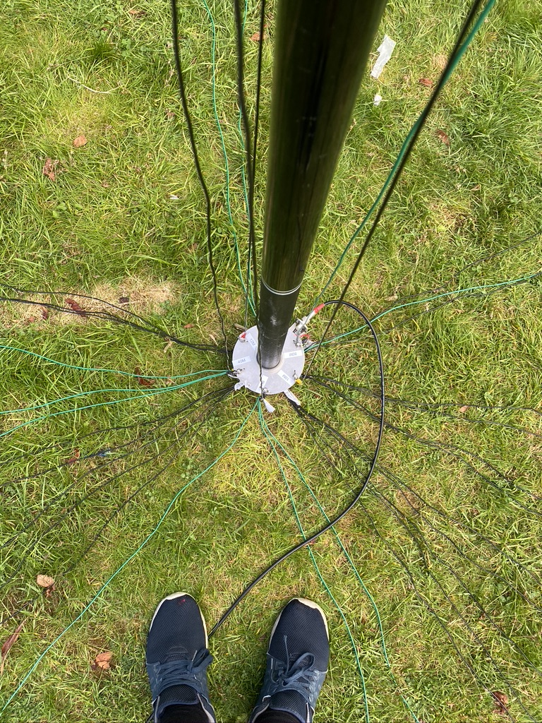
view from the base
keeping it tidy
gaps to fill
now with added elements
adding elements
I’d need to an exact recount (will do so later) but I think I now have enough radials to accomodate the 80m vertical.
With having added the radials it was time to test ! For this I use FT8 as it has a great map and includes a signal report when a QSO is complete.
Reaching Kuwait on 17m
I was now reaching Kuwait on 17M and even better was that I could see the call sign in my WSJTX screen – i had to give it a try ! And sure enough within a few minutes (this guy was was getting alot of QSO’s in) I had made contact !
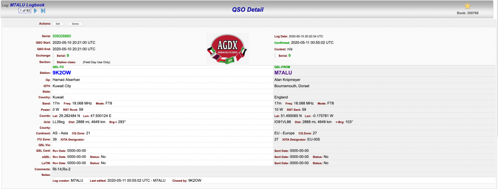
Contact with 9K2OW in Kuwait – a staggering 2,888 miles on 10 Watts of power !
So i think i could continue to add more radials, but for now I’m happy with how the DX Commander is performing and the radials are performing their function. I will investigate more ‘science’ based ways of radial performance, but his helps for now !
So its been a bank holiday here in the UK and its allowed me to work on quite a few different things (including re-wiring the Mazda Bongo door looms). When I got the DX Commander it came with enough wire for 4 verticals and the radials to support it, but I purchased some more wire from Radio World, namely the Watson Radio Products EQ Equipment Wire which goes for 40 per meter. I used Radio World as I had other bits and bobs coming from them as well, and my word, they are so QUICK to deliver (UPS Everything !).
I checked from the list what additonal wires I would need to make up., in this case only the 10m and 12m. Having learned from trying to measure the wire indoors I now measure all my wire outside. I have 3 meter workmans metal tape which so far has done me brilliantly in getting accurate measurements.
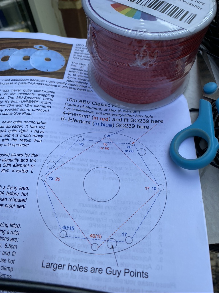
So the first part was to obviously lower the mast, and then remove the existing wires, Going from 4 to 6 requires adjustment as per DX Commanders docs (pg 2) here.
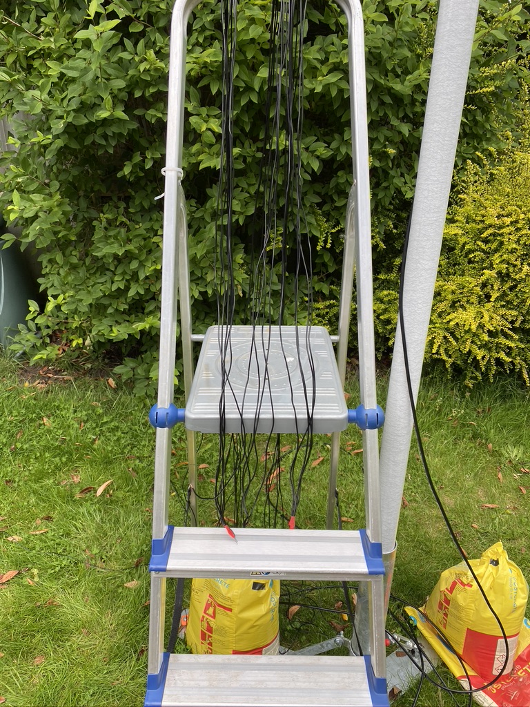
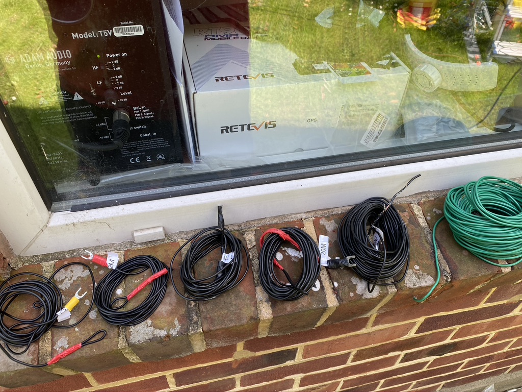
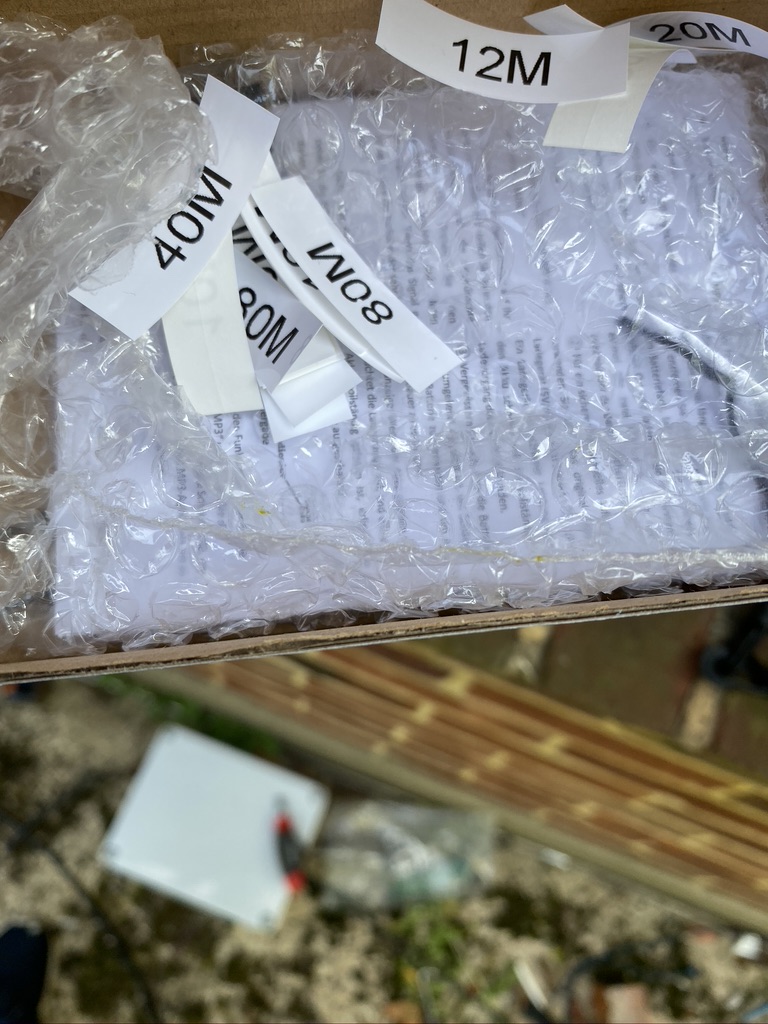
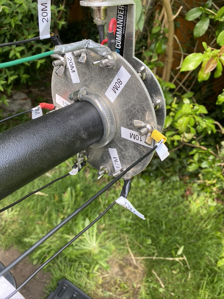
I also reprinted all new labels, removing the existing ones. One thing I didnt do orginally was to put labels on the bottom plate, so this time I would ! First I organized the cables so they was easy to pick up add, not having things on the floor and in a mess really adds to health and saftey when doing this kind of work.
wires in respective order of frequency (10,12,17,20,40,80 – the long green monster!)
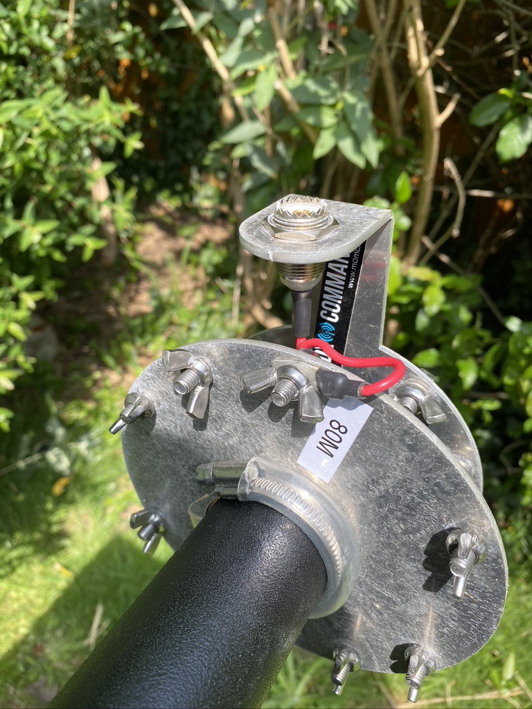
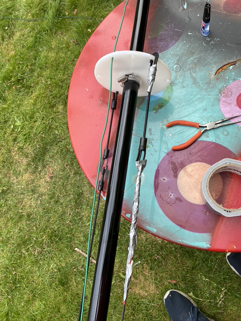
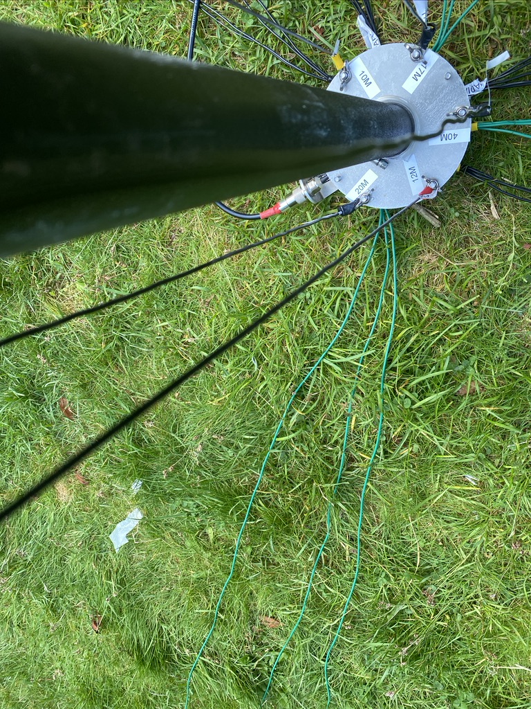
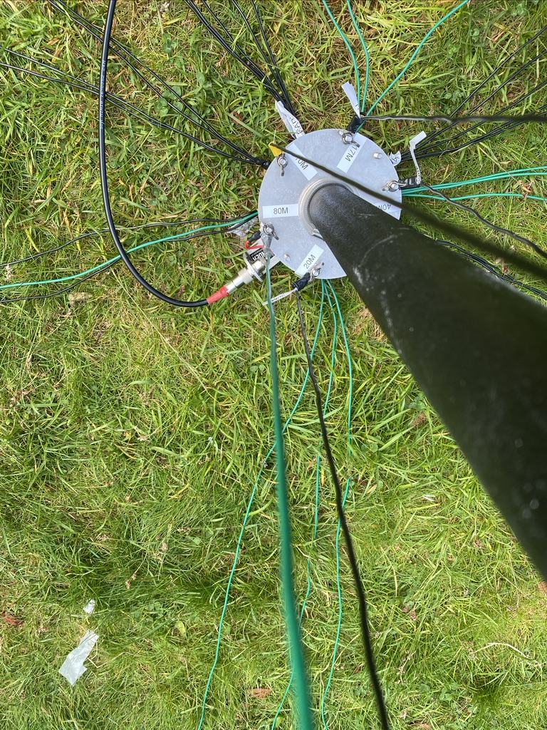
With the mast lowered I followed the instructions and relocated the SO239 feed wire and the 80m connection
movement of feed wire and labelling up
What really helps is the DX Commander stickers. On my spreaders i do them so that they should be aligned when looking down the mast, this gives me a good point of reference.
To start with I just feed the 80m wire up to where it would be for 30m and taped it down. I then worked around the mast feeder positions adding labels as I worked in each new wire.
its not just a great little radio
its a box for all the stickers!
keeping the stickers safe
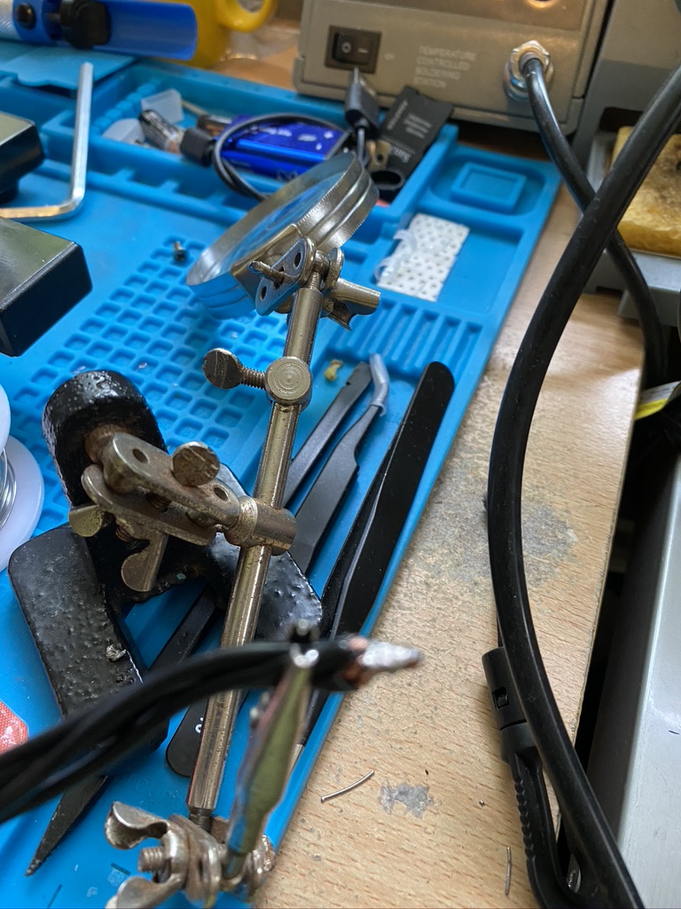
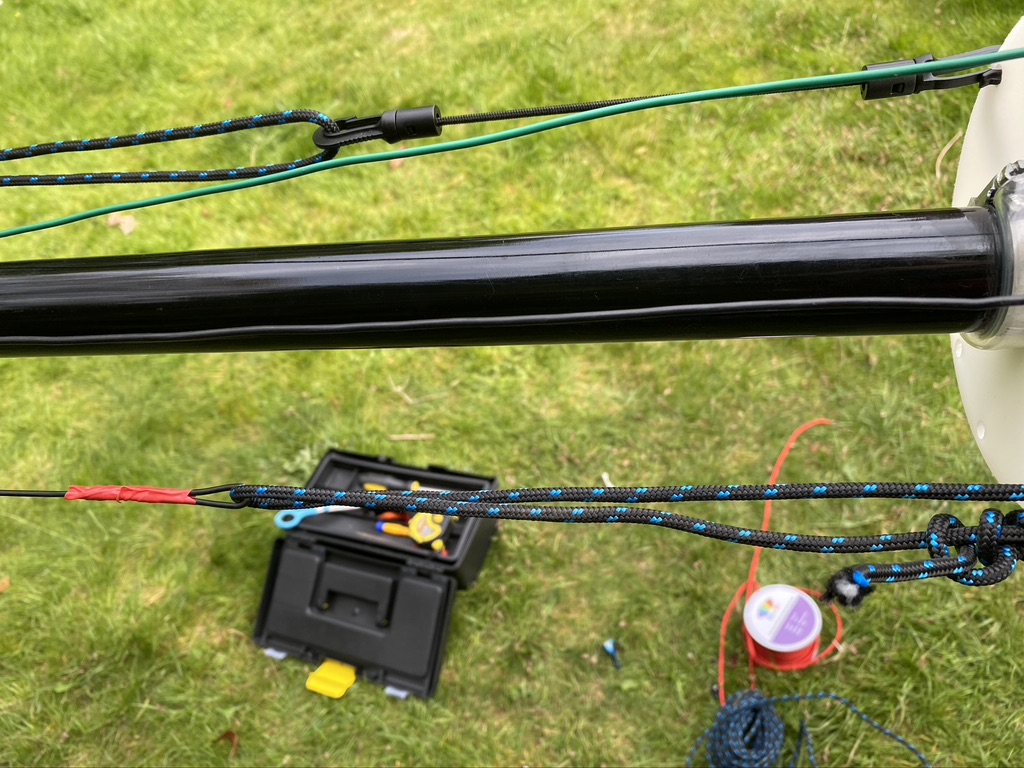
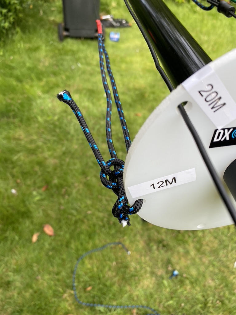
Now the DX Commander/Calum does say that the clips used on the paracord are hard to undo once set, as I found. Having to try and extract one, manage to break a clip, and I had no spares. So, i thought, well superglue it is then ! With using the YOCTOSUN Hands Free Magnifier, i was able to get it to glue pretty much back on. I was then with the existing cut paracorde and elastic cable to add the other elements which required some vertical tensile strength.
repaired clip holding out
loopbacks doing their job
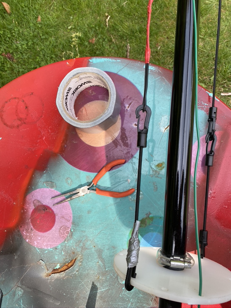
some additonal ‘temp’ fixes
12m, tied directly to the lower guide/spreader
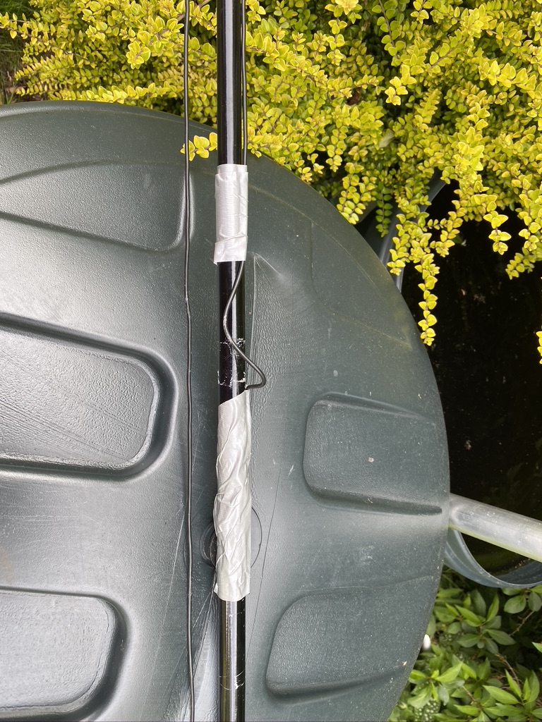
I continued to add all the elements and was happy with the tension and how tidy they are. I also took some time to put some tape around the clips where sometimes the wind will blow and wires get caught in the juberliee clips. As I’m not taking the mast down and collapsing, this wont effect me in the short-term.
nicely labeled plate
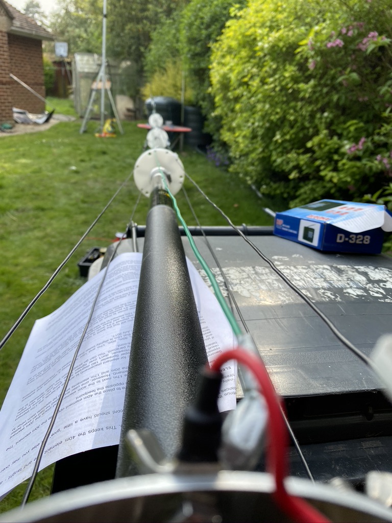
tidy going up
some ‘fettling’ with tape for now
wires in place
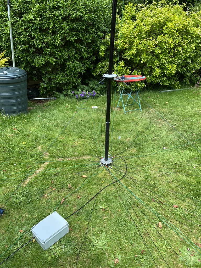
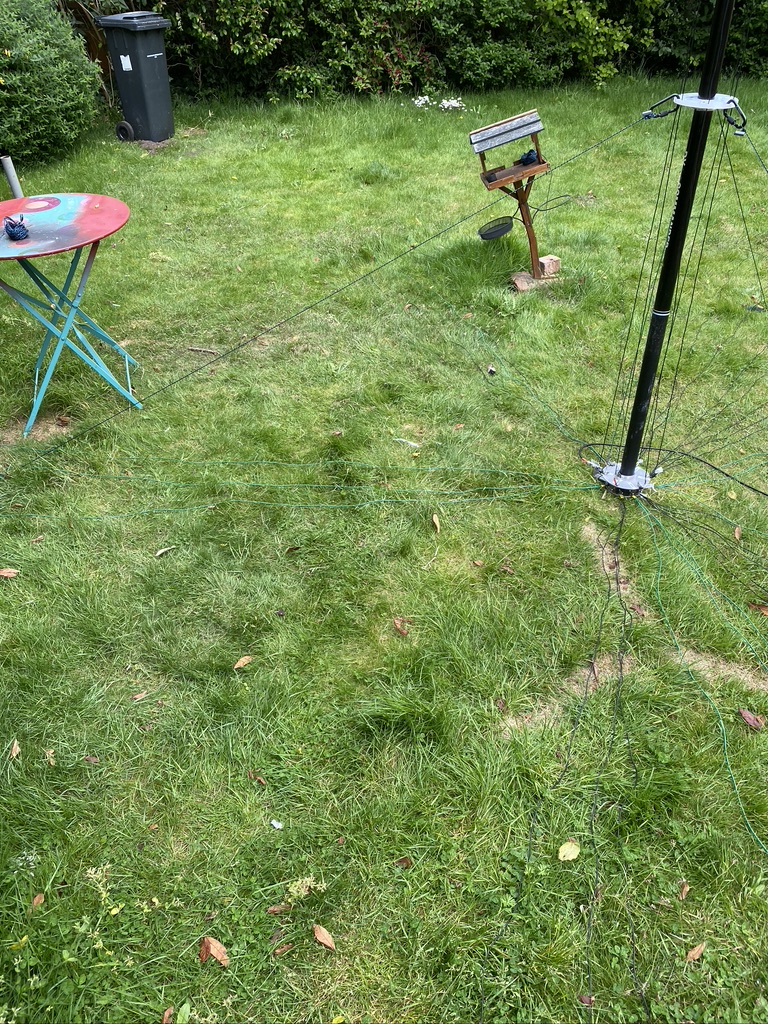
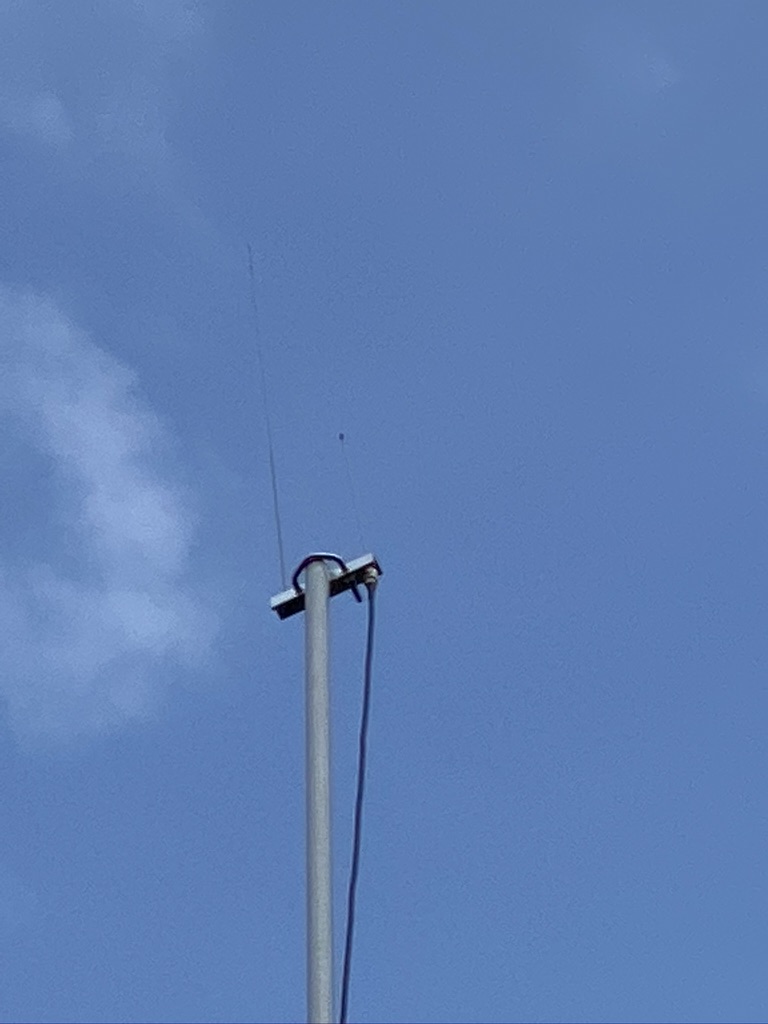
With assistance from my son, we got the mast vertical and I could start adding the existing radials I have. I add the radials in a N/E/S/W layout starting from the feed point, and adding where i have capacity. I also done a ground-visual of the 2m/70cm with my iphone (10x max zoom) and could see it was in good shape up there after I had raised it on Friday.
approx 28-30 radials
spreading them out i go N/E/S/W, then fill the gaps
A quick visual on 2m/70cm antenna
radials and a visual of the 2m/70cm mast
Testing and Results
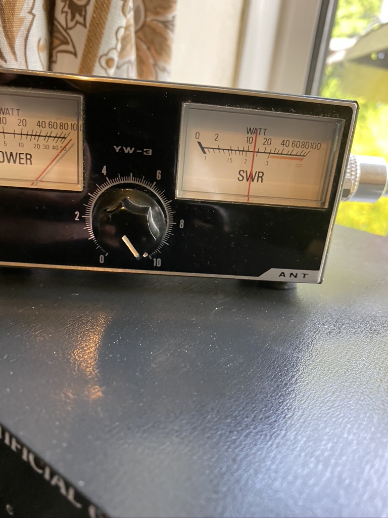
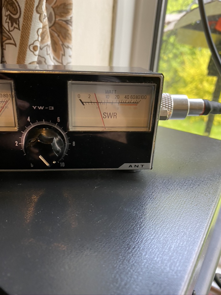
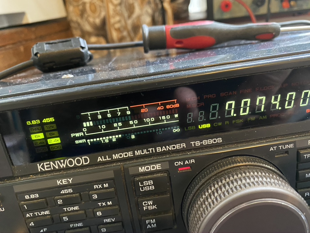
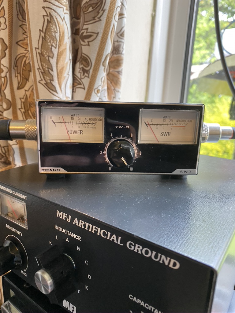
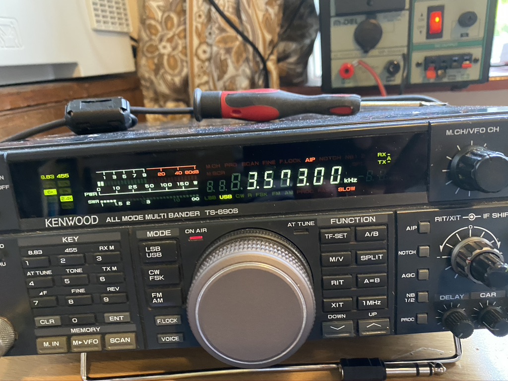
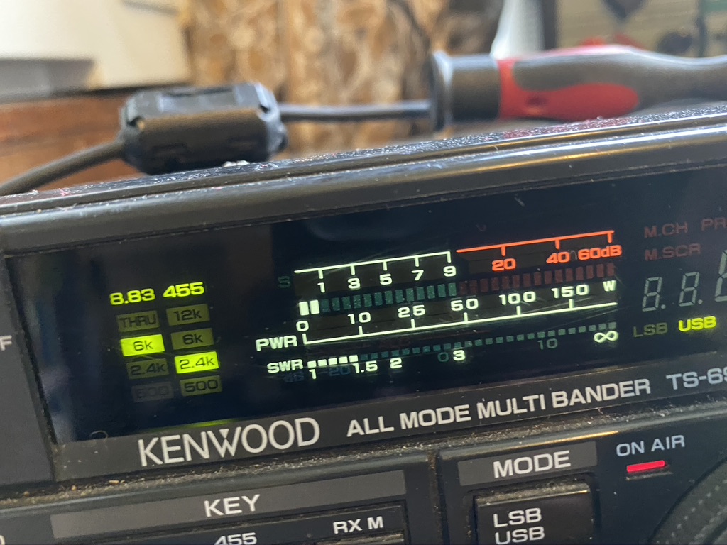
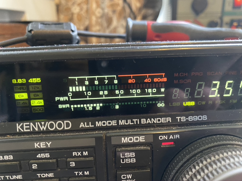
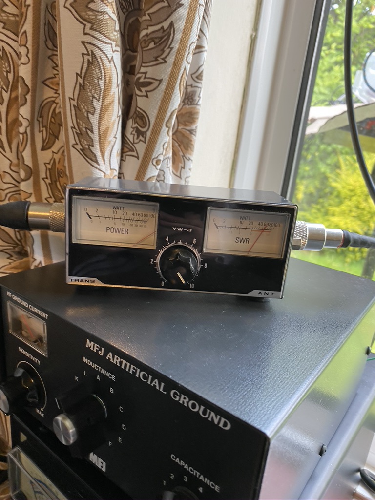
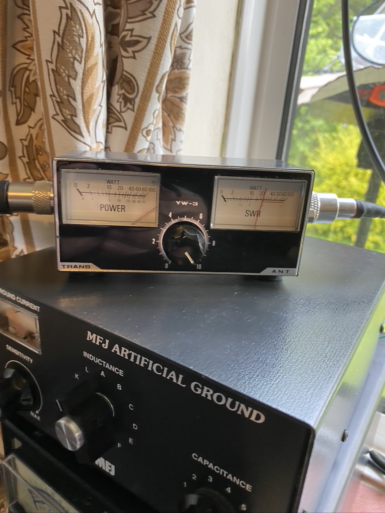
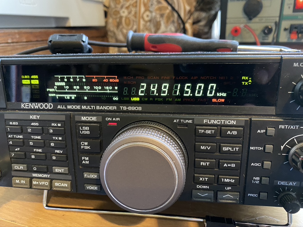
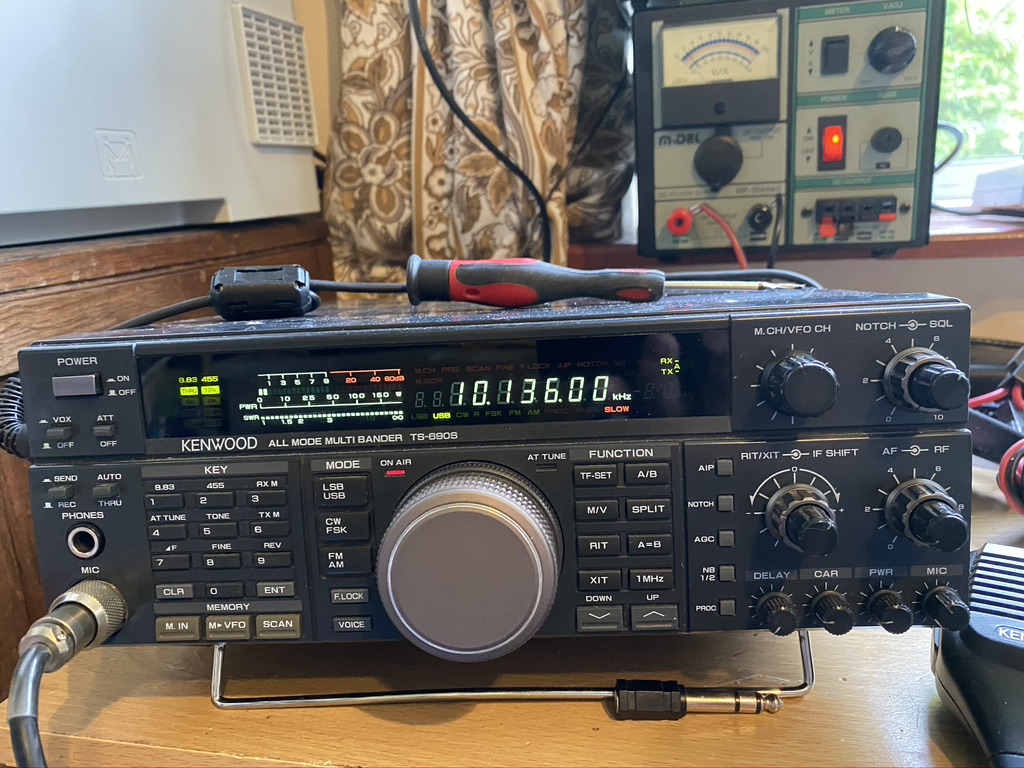
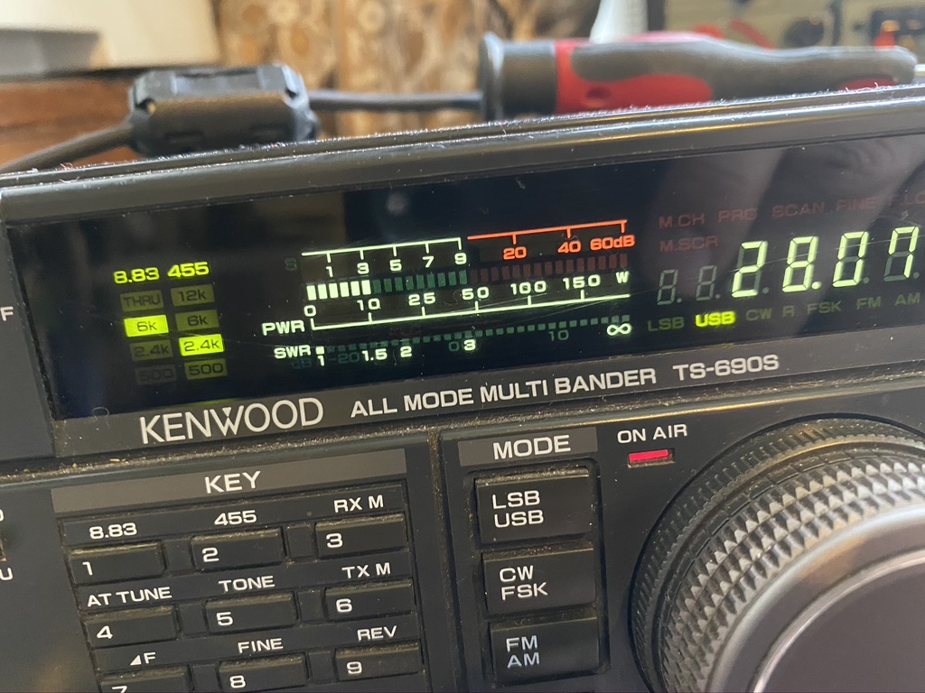
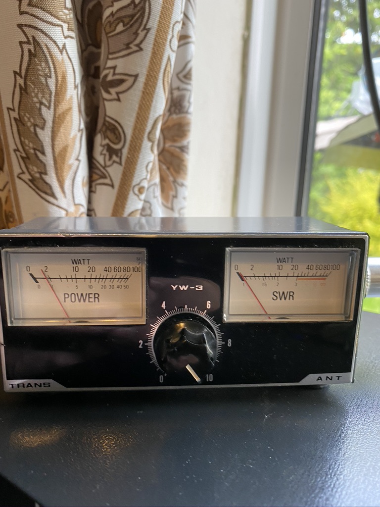
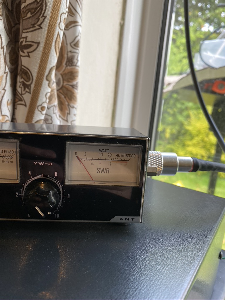
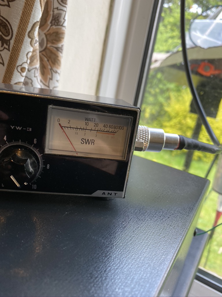
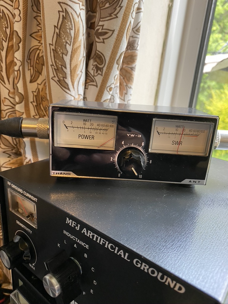
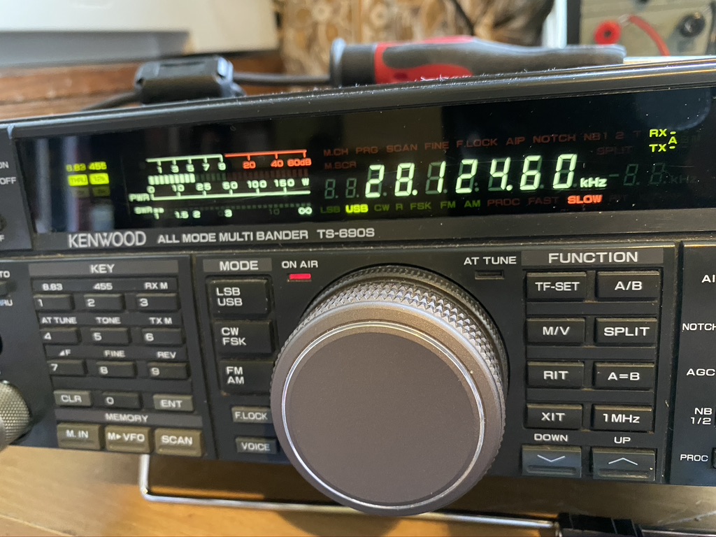
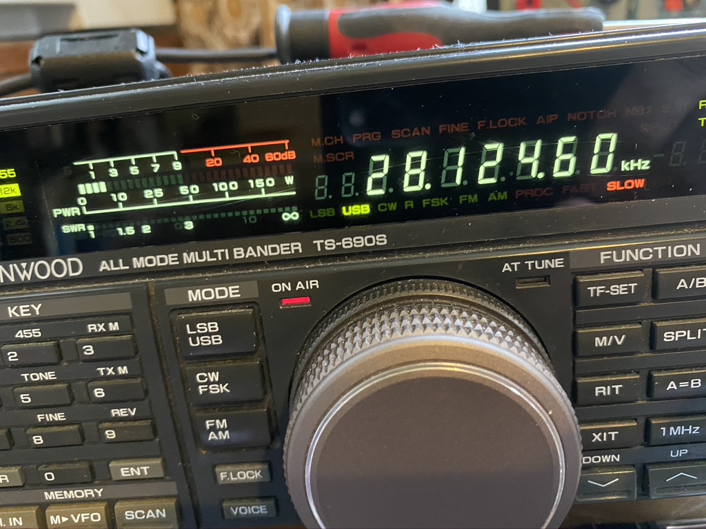
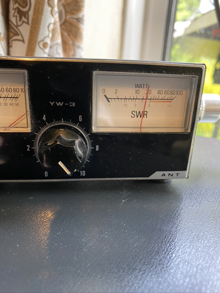
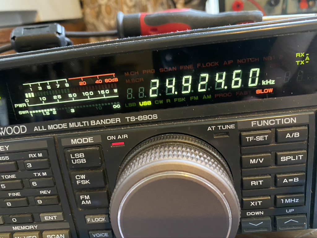
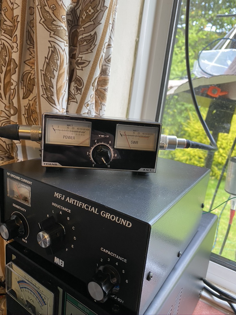
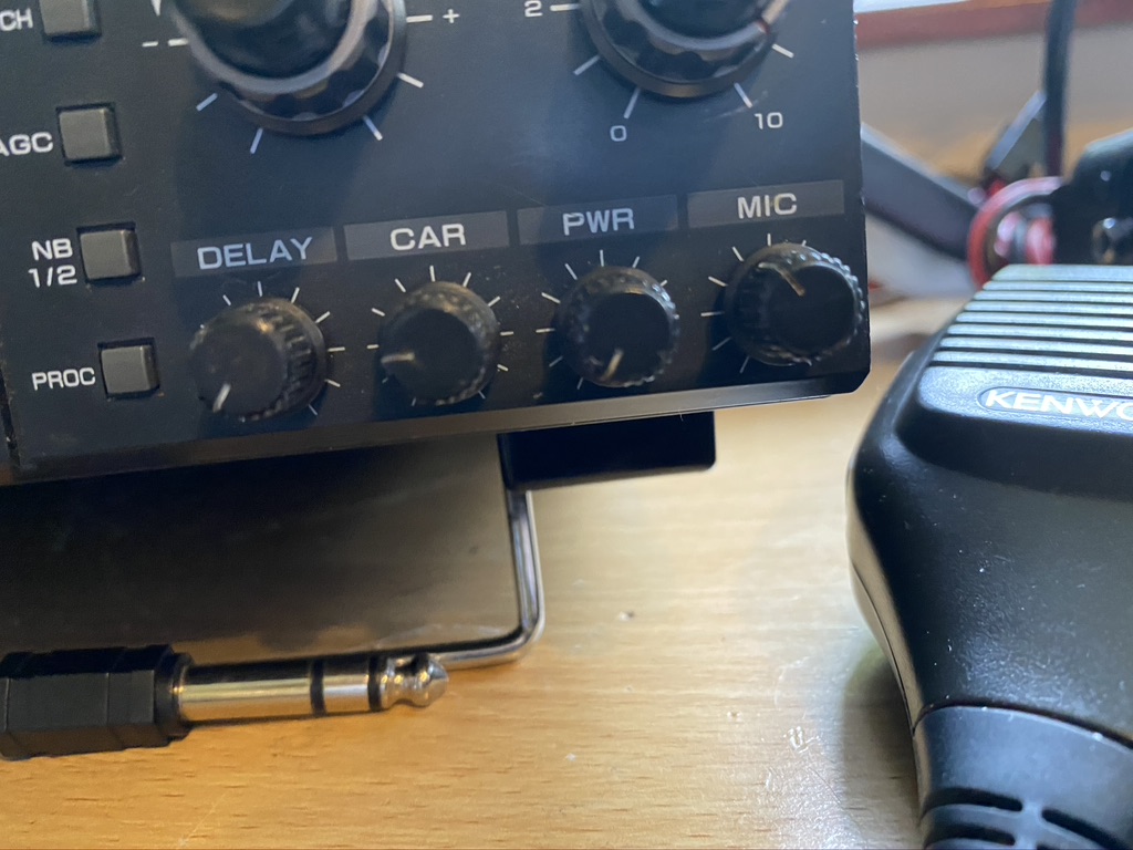
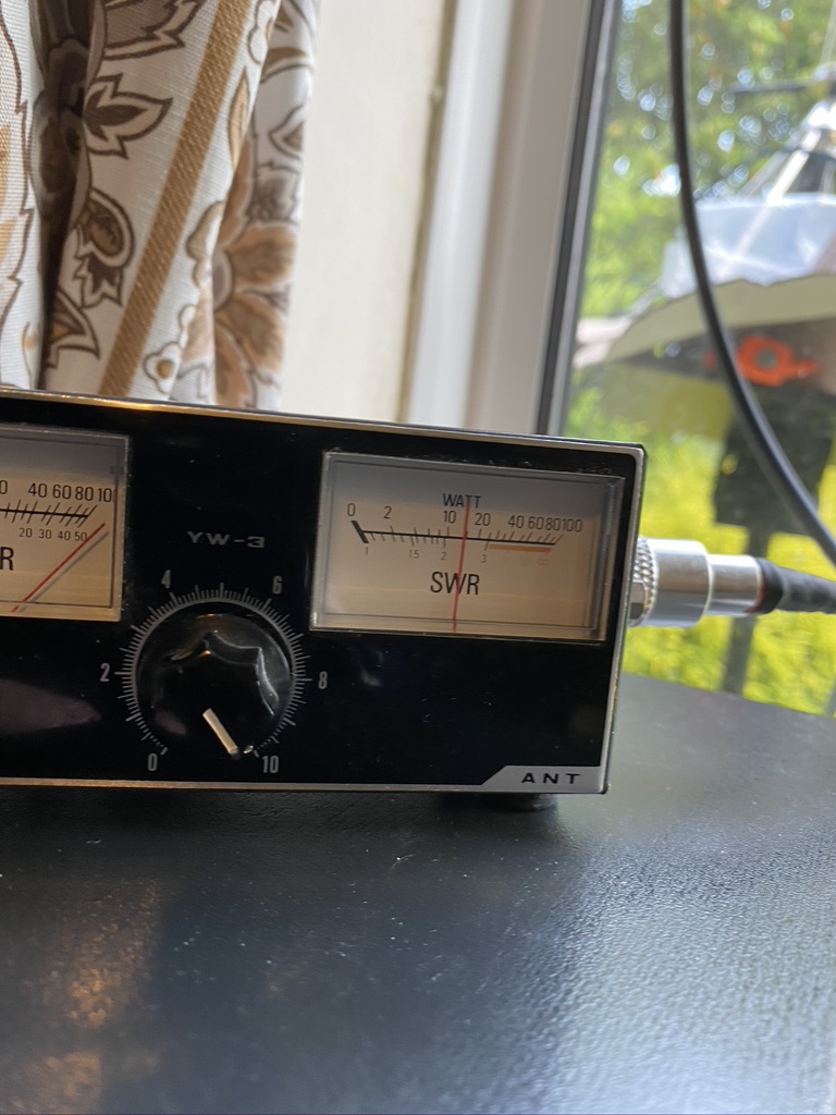
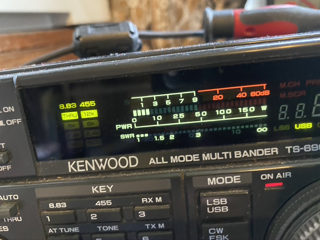
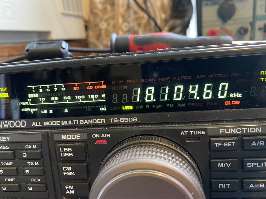
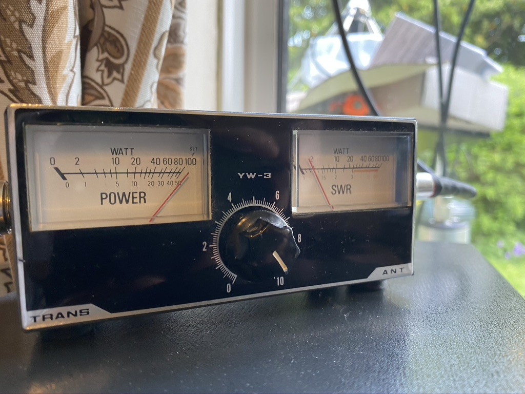
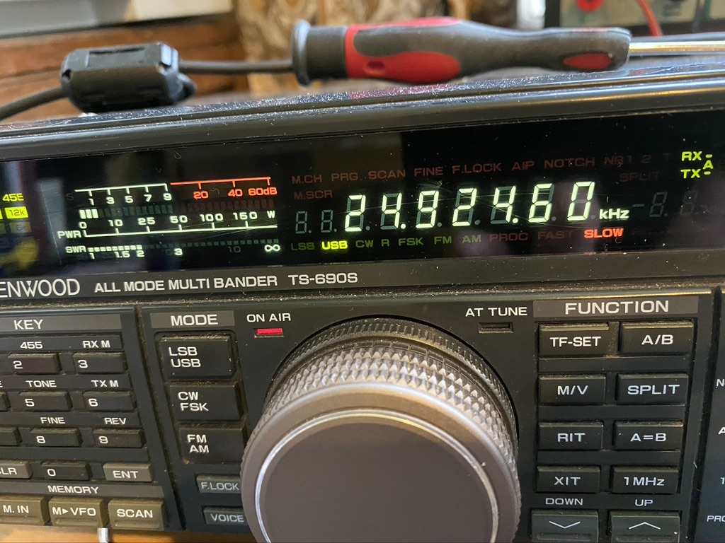
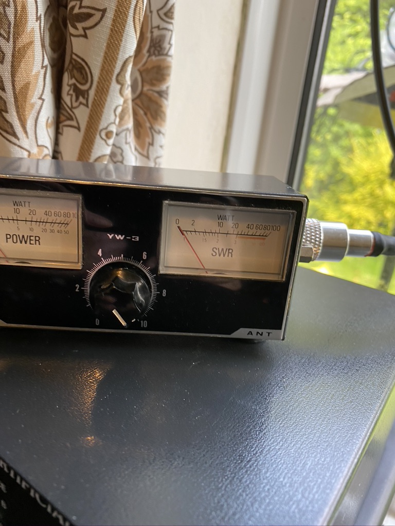
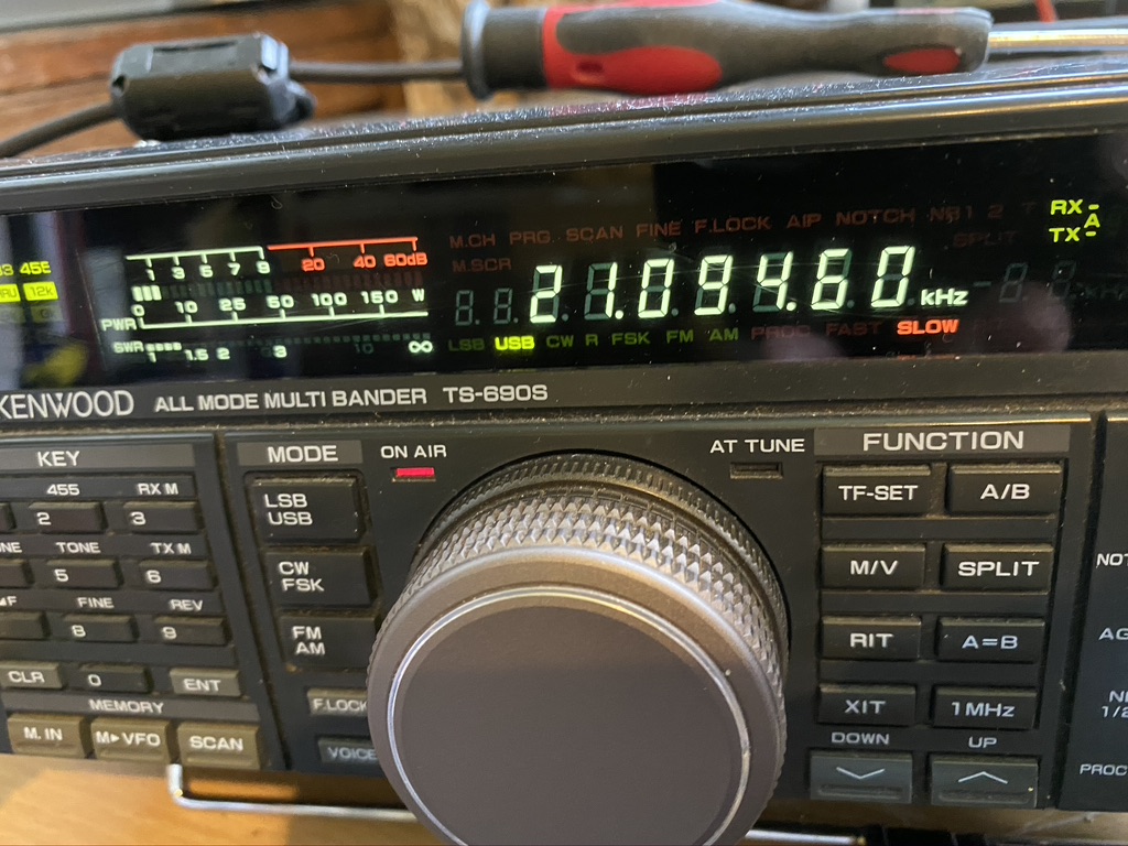
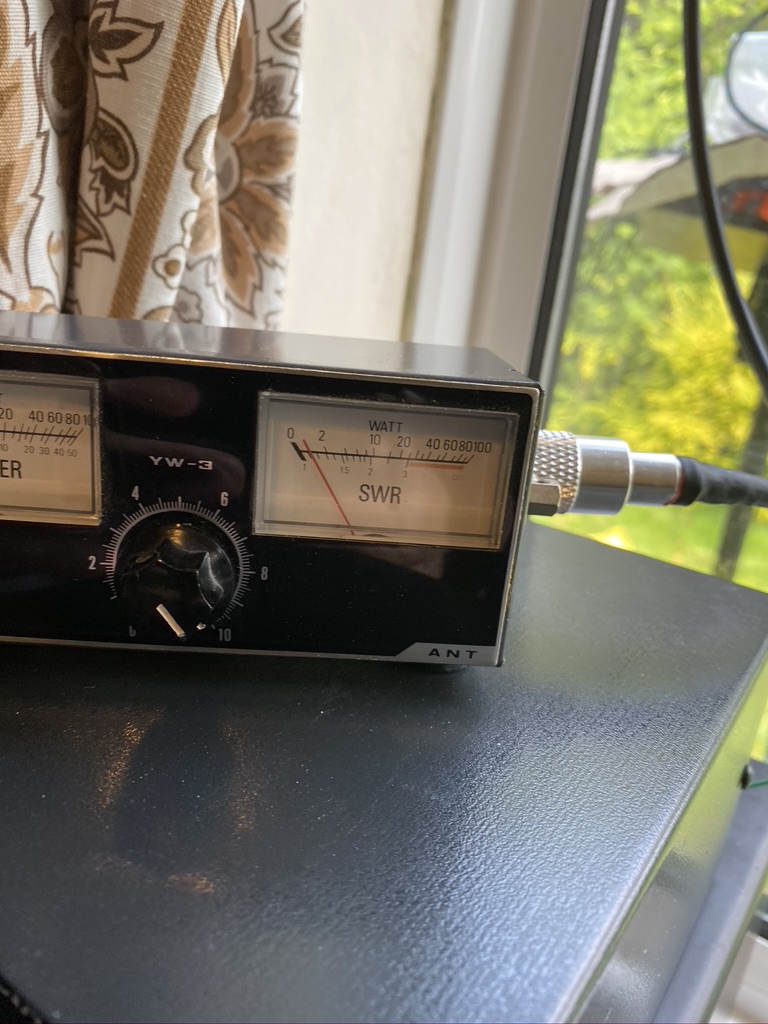
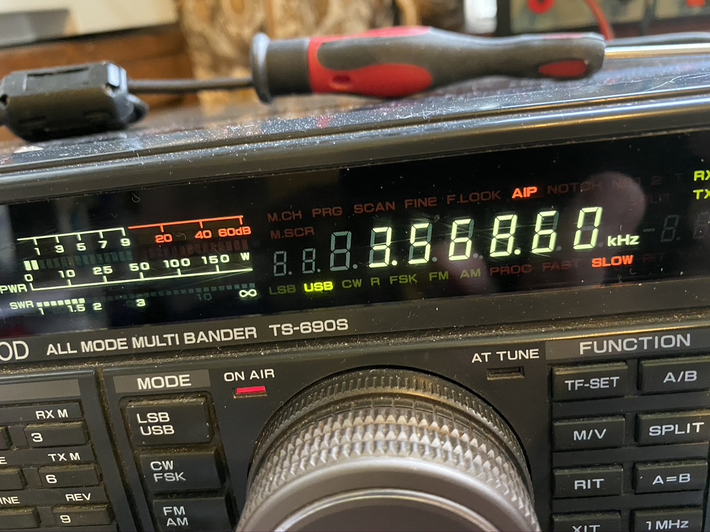
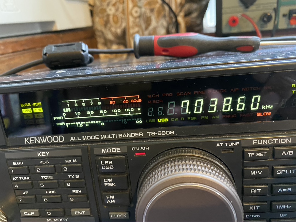
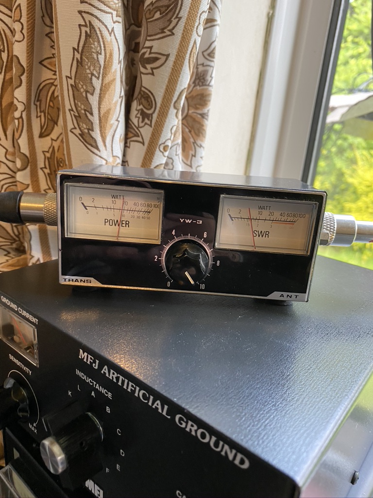
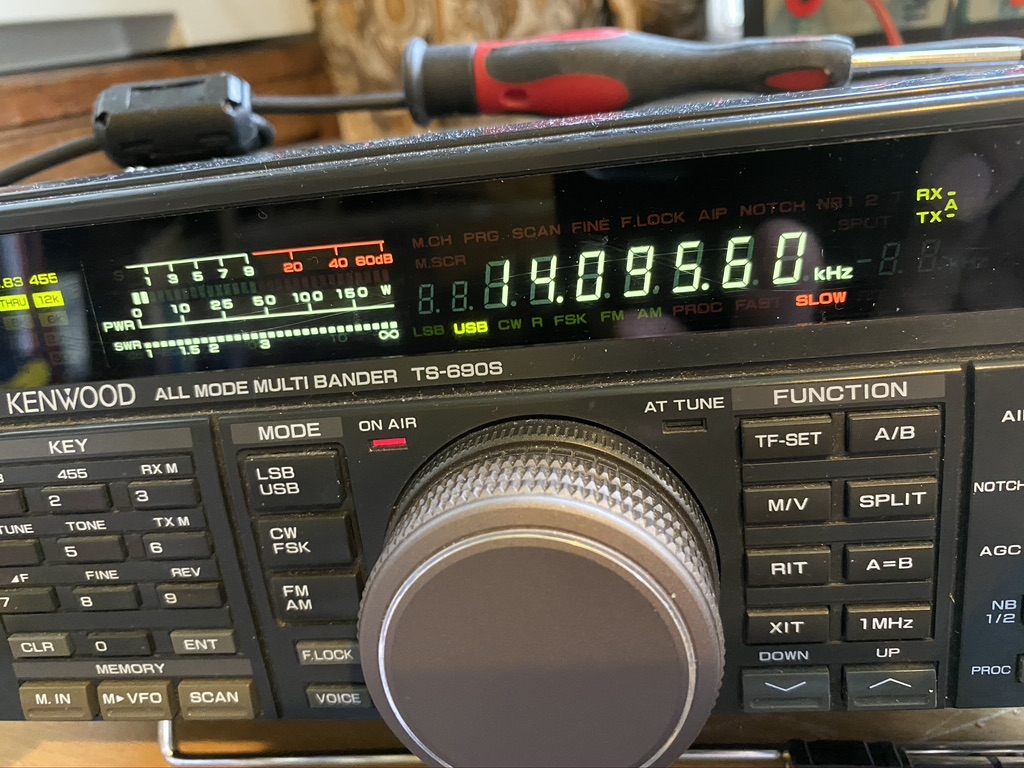
So the next step would be to test. For this i used the two main data modes I currently use, being FT8 and WSPR. I used WSJTX v2.1.2 and finding a ‘gap’ to press the ‘tune’ button. This would give me repeatable results. I am using the TS-690S internal SWR reading and a 2nd hand HF SWR Transceiver (YW-3) for the external readings.
Band
SWR Transceiver
SWR Meter
Notes
10
1.1
1.3
12
2.2
80
17
1.4
1.6
20
OFFSCALE
2.5
RX is very clear 5/9
40
2.2
1.1
80
2.1
1
160
OFFSCALE
To be expected
30
OFFSCALE
80m wire ?
15
1.6
3
Does the VV-3 work at this frequency ?
12
2.1
3
FT8 Testings with new elements on 10+12m and resonant frequencies/others in WSJTx
Band
SWR Transceiver
SWR Meter
Notes
10
1
1.2
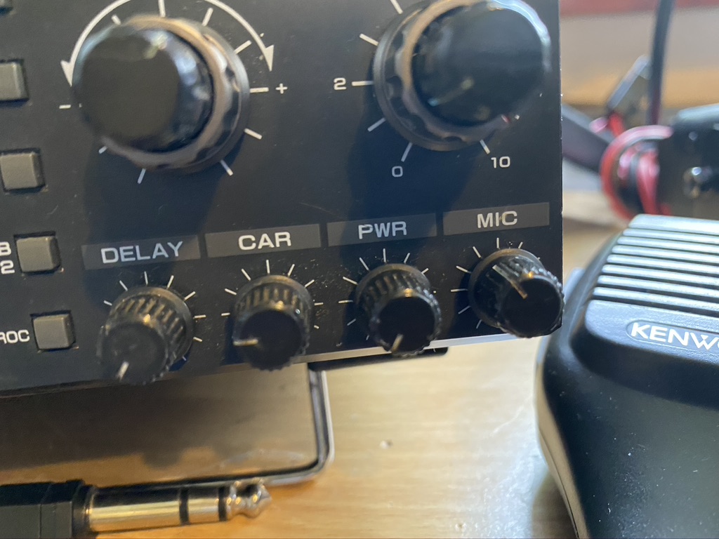
5 Watts is the min setting on the transmit
12
2
2.5
17
1.3
1.3
20
OFFSCALE
40
2.9
1.1
80
1.5
1.1
160
N/A
30
N/A
15
1.4
1.5
12
2
2.1
I am really impressed with the S.W.R. on all the bands, whilst 20M gave a high reading, i suspect that the curve on this band is quite specific. Reception is very strong, so the wire is doing its job in selecting the fequency nicely.
Whilst I wasnt expecting 160m and 30m to be available, for thorughness and future recording, added them (should of done 6m in hindsight). I was happy to see 15m and 12m resonating nicely with low S.W.Rs on of 1.6 and 2.1 respectively.
I will upload a gallery as there is so much evidiential data to show,so browse thru at your lesuire.
*** THIS POST CONTAINS INFORMATION ON BUILDING A MAINS RF FILTER – IT IS NOT AN INSTRUCTION. IF YOU BUILD THIS IT IS AT YOUR OWN RISK ***
So I never knew just how much can be done to reduce QRM and where it comes from ! Having bought some ferrite rings and having mixed results, I found this excellent site from M0NWK who thanks to his equipment and setup can really demonstrate how the chokes work, heres the site which also includes a link to the video here
My build was slightly different, as I cant wire in a main tripper, I can wire in an extension in from an existing outlet, I was pleased to see that someone had already asked this question on M0NWK’s page.
I kept the same ferrites as M0NWK but a smaller box and bought a mains filter to which the ferrite-wound would attached.
Heres my part ilst, I use Amazon Prime alot because things arrive quickly and via decent couriers, if I wanted to get this done in less time I could of sourced cheaper, for example the 6 Way Mains Connector can be bought from Richer Sounds cheaper, but I dont know how quick they deliver or who they use.
Table of parts used in the construction of filtered mains feed
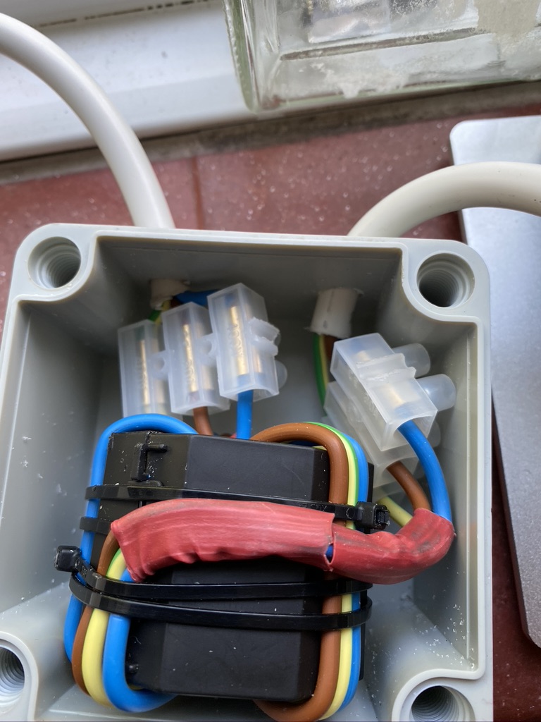
I started with stripping back some of the 3183Y Flex to bare out the live, netural and earth wires to wind around the ferrite. The heavy gauge of the wire made this quite a challenge, certianly being able to open the ferrite made a big different in creating a well fitting wire to the ferrite. I used cable ties to keep the ferrite and the wires stable.
The Terminal block comes in a massive pack, but its really good quality and will undoubtedly have many uses in the future, so worth having around. I attached these to the ferrite and wires, but not before attaching heatshrink to the wire going into the terminal. This not only looked good but kept the cable tidy.
I then set about measuring the thickness of the coax to make suitable sized holes into the box. I went in thru one side and so the mains feed and outward to the filter strip plug, nicely gapped so the terminal connectors in the box had a good seperation from them.
When drilling the holes I used a regular drill, but fettled the holes with a small round file to get the edges smooth and remove all the excess produced from the drilling.
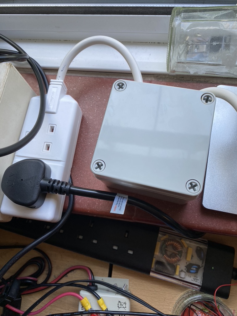
The choke in its box – right side is the feed in, left side goes to the power strip with further mains filtering on.
Before plugging into expensive radio equipment i tested on a B&Q light to ensure it would turn on and off/and light. (The lid is back on at this point) As this was my first time using this I kept one hand in my trouser(probably short) pockets, but the lights came on and no problems. I then set about putting it into the mains outlet and to connect the additonal filter
Mains filter after the RF filter which supplies the transformer
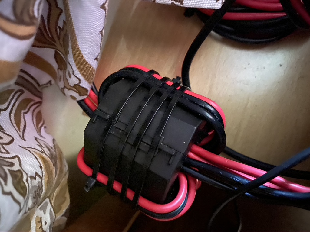
You will see the parts list contains 2 ferrites, the 2nd one went onto the back of the radio power supply feed directly
Ferrite on the input voltage to the transceiver
As this is 12V DC and whilst can give a nasty poke, a box isnt necessary here.
I went back to the LW frequencies that had previously been plauged by a ‘buzz’ that had now completely gone ! I went onto 80m and 40m and weak stations were getting thru and loud stations were BOOMING.
Whilst this was a fair amount of work, I’m satisfied it has helped reduce my QRM further.
So having got the bhi DIL DSP Receiver, the amount of QRM I was still getting wasn’t good. Although I was slightly tired, i really wanted to solve this issue.
I followed the DX Commanders Youtube posting on QRM here
https://www.youtube.com/watch?v=xF2wFJBpu_I
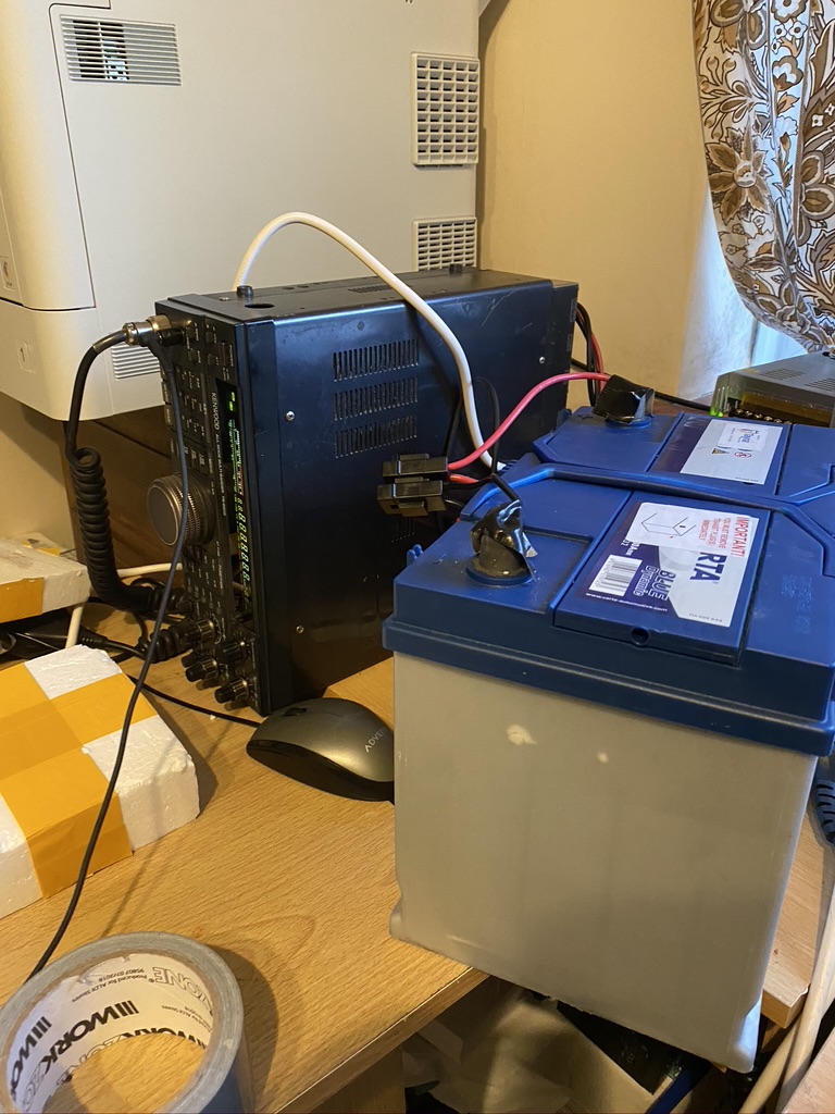
So i then set about unplugging things around the house, the first thing I found was an electric blanket ! That put out a huge buzz, but there was still plenty of ‘noise’ amongst the signal. I turned everything off in my ‘lab’ and used a car battery to test –
Car battery, less buzzing…
So off a car battery there was a big reduction in noise, so it was something in the powersupply or surrouding room
At this point I used several of these magents and put on the power line in, HF and transformer
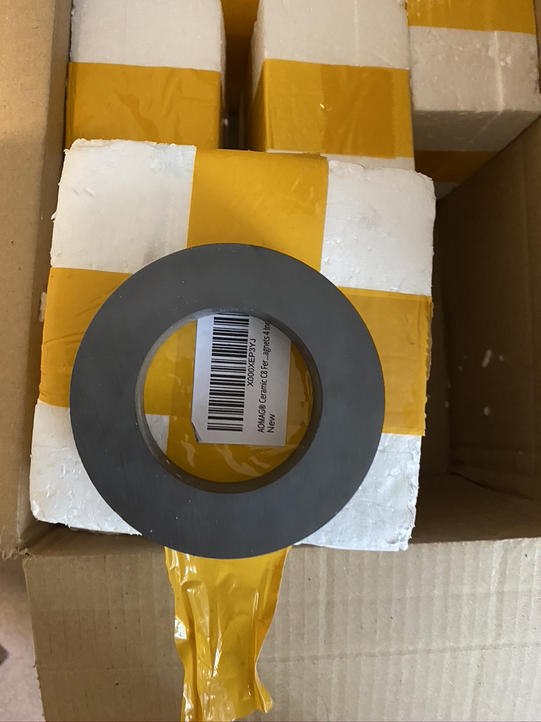
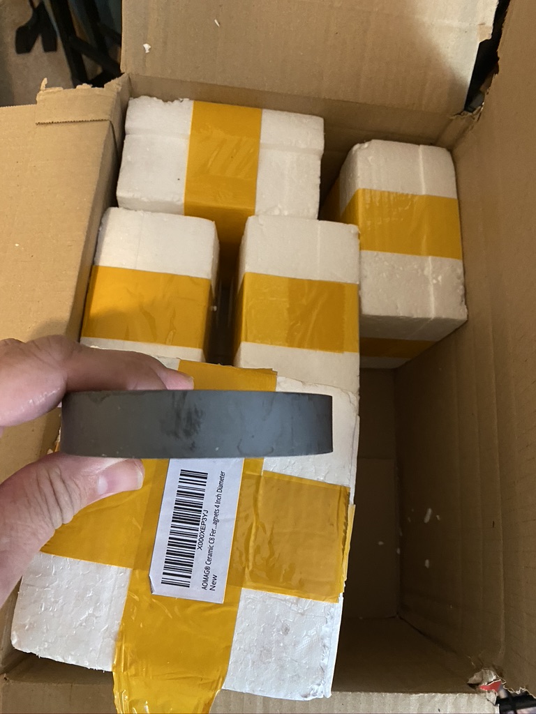
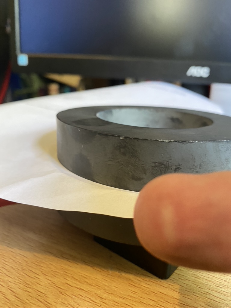
very well packaged
big ring
the thickness
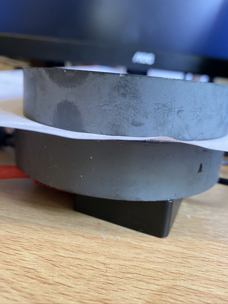
lets see what happens when you put two togehter
thankfully this is just my finger…
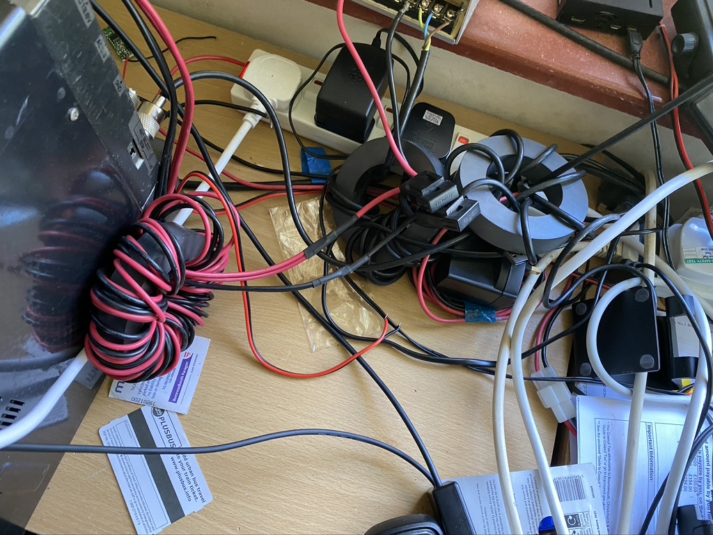
I set about winding, but still noise 🙁
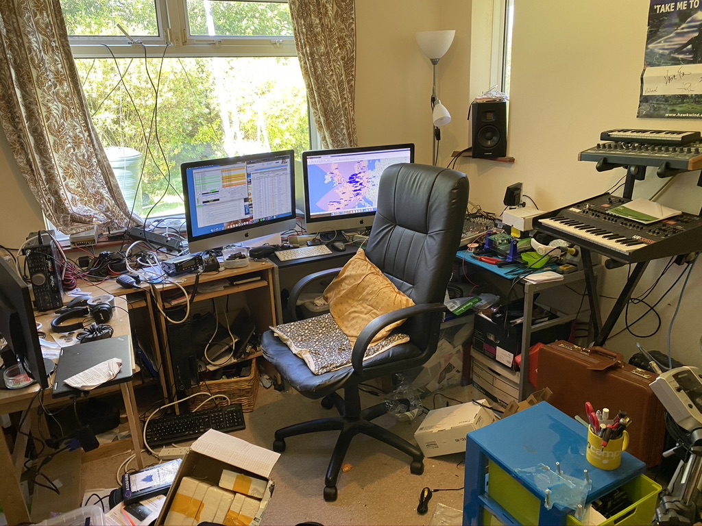
what a messy lab
i’m working in this mess 🙁
winding and messy
By this time, i was still getting less, but still a big interference. I unplugged *eveything* from the transceiver and it stopped ! So it was something being plugged in.. I went thru each device, lo and behold the xggcomms CAT port was the main offender ! By this time it was getting late, and some much needed family time with a few brews and a good film was required to consider the next steps.
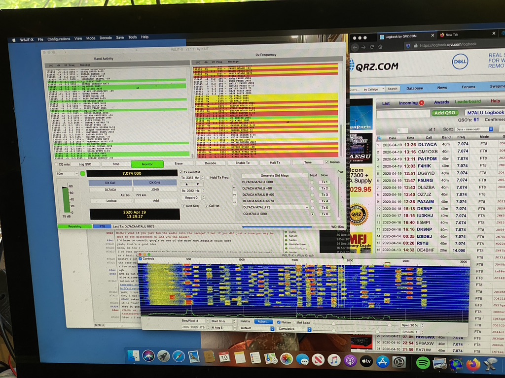
After the film and a nice walk of the dog at 11PM (to avoid other dogs/runners/etc) I cam in and started searching for ferrite cores, sure enough amazon had a huge variety, and on PRIME next day, so I ordered think, great i can get these Monday and get going ! Amazingly, even tho i ordered these at 11PM+, they was here the next day ! I was going to tidy the lab up, but set about attaching all the chokes I could to the cables between the mac and transceiver. The difference was amazing…
FT8 came alive very rapidly !
Within a course of an hour, i had made 9 QSO’s on FT8 on 40m, with 3 already confirmed on QRZ ! I was so happy that everything was working really well !
I think I am going to upgrade my chinese power supply which is meant to drive power-strip lighting, which is fine for VHF/UHF (A recommendation from FRED IN THE SHED on 27Mhz) but for HF I will get a decent 30~40 Amp campable linear PSU for the Kenwood to further reduce the QRM.
Now to stop playing on WSJT-X and tidy this place up !
This is where I miss being a amateur radio club, asking advice of seasoned operators. Thankfully I have my long-time IRC and expat friend PA2TG to call on assistance. I asked about eliminating QRM on HF as I was looking at the many different options available, and varying costs.
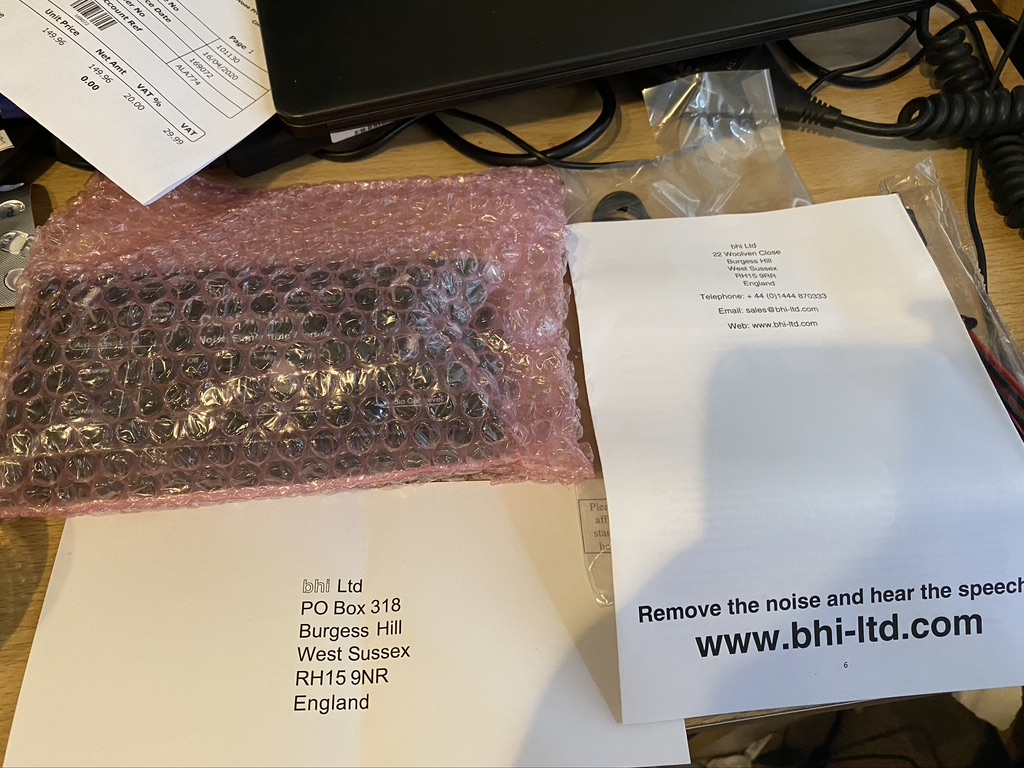
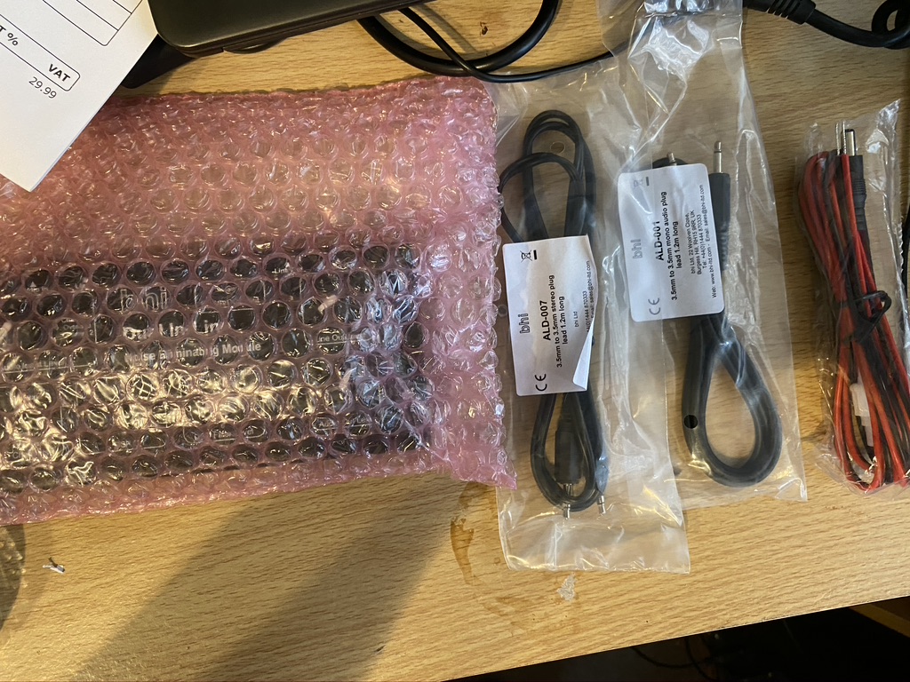
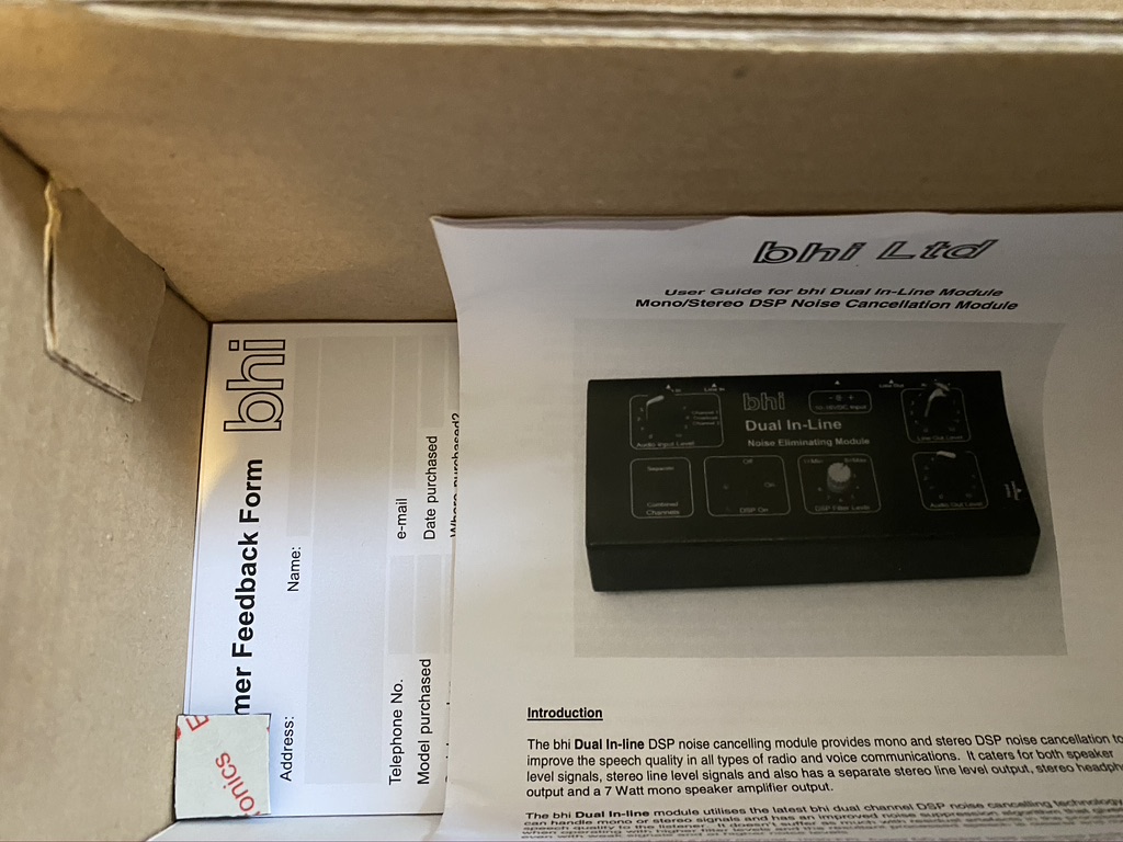
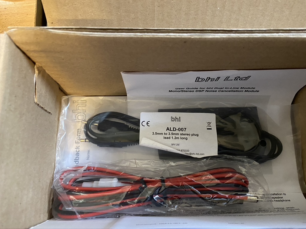
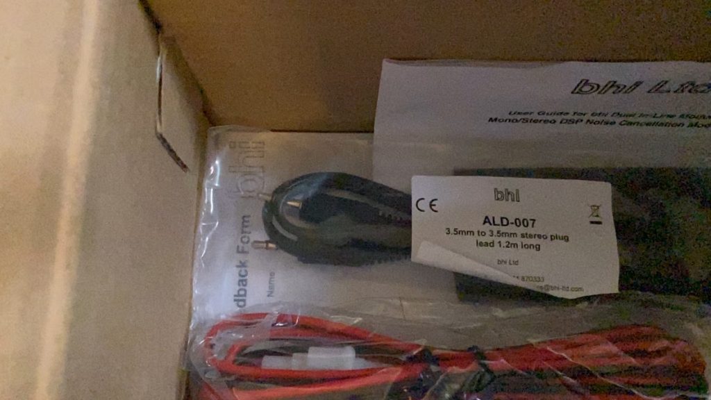
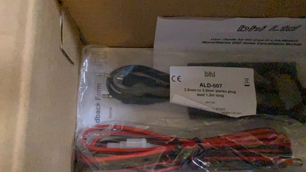
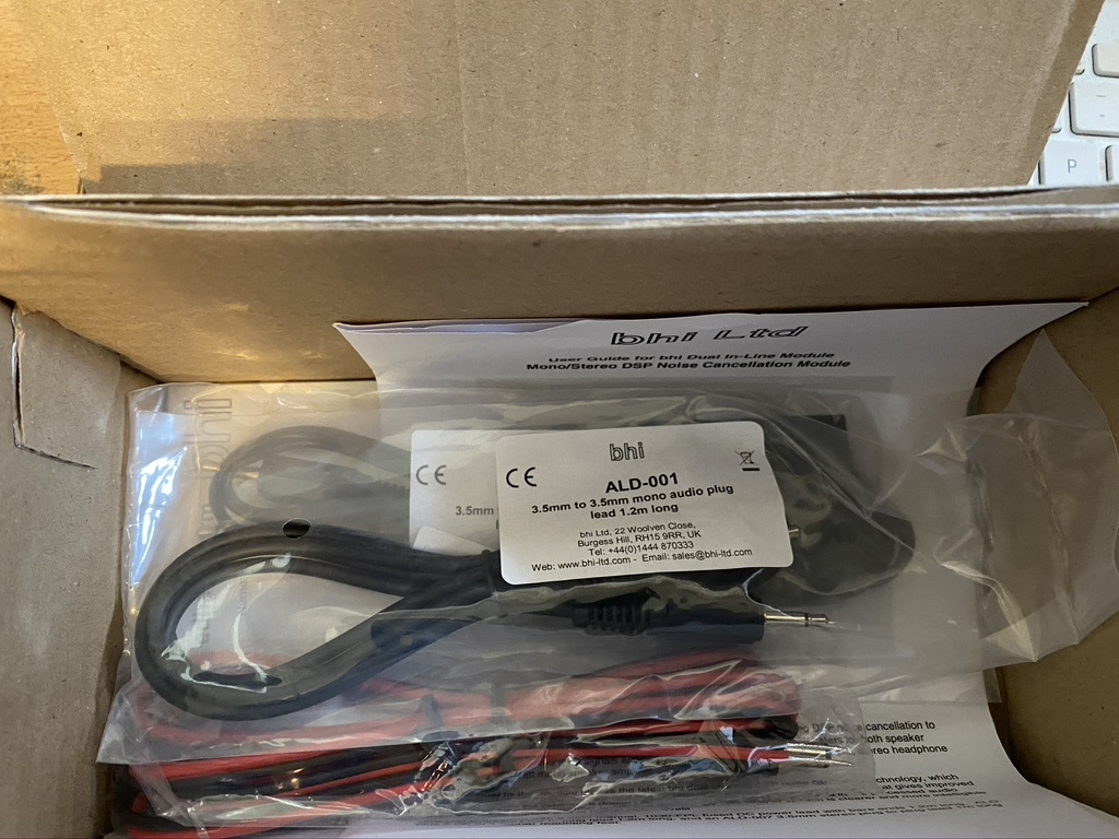
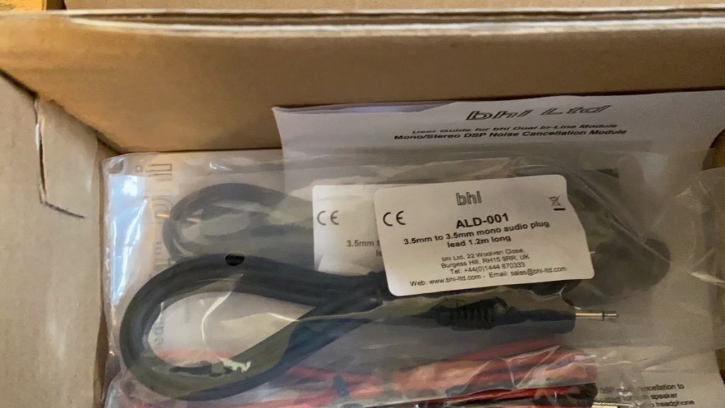
After reading my email, PA2TG suggested the BHI Dual-In-Line unit for me, which I ordered from RadioWorld who were incredbly prompt with next day delivery! Whilst I wont do a full review yet, here is the unboxing of what looks to be a very worthy addition to the shack !
BHI Dual In Line Unboxing
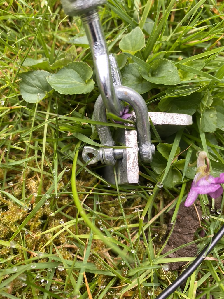
I also take my responsiblity of being a Amateur Radio Operator seriously, as much as its a ‘hobby’ it is very well taught module of ‘Saftey’ in even the Foundation. Some may laugh at ‘wiring a plug’, whilst I found the difference in fuses and grid types very interesting ! One thing I do take seriously, and check my antennas every single day. One ‘benefit’ of the lock down is that my antennas are staying up longer, and the guying/mounts are amazing, but today I found that one had completely come off ! Under observation I quickly repaired the guy rope and restored the tension to the mast.
Saftey inspection found the pin had completely come out the ground stake, quickly fixed and tension/support restored.
I have been doing other things in the shack, but will right a summary rather than lots of little postings.
So after having so much fun on 40m, I wanted to get the rest of the wires up
So far I have 40 and 30m up (the longest wires), with 40M getting the most use on FT8 (Plenty of contacts logged, and several confirmed via QRZ!)
I had two remaining shorter cables to mount, the 20 and 17. 20 was of particular interest as it has so much going on and seems busy day or night !
Before adjusting the antenna i done a quick test on 20m, and the S.W.R was way off the meter on the radio, so was very much needed if I was going to get out.
I set about re-measuing the wire and 20m required no correction thankfully and 17 only need 6cm adding, which I set about doing. I brought the mast down and rewired.
I started the transceiver and put wsjtx onto 20m. Sure enough within a few minutes, i had made contact in Poland on 20m with a very good db result.
I’ve not tested 17 yet but I’m equally confident that I will be able to get out.
As per previous exercise, here are the S.W.R. measurements with 4 elements up
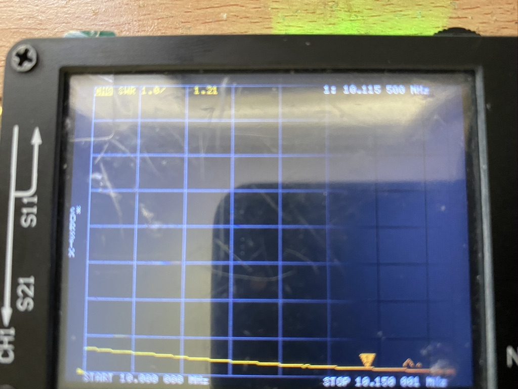
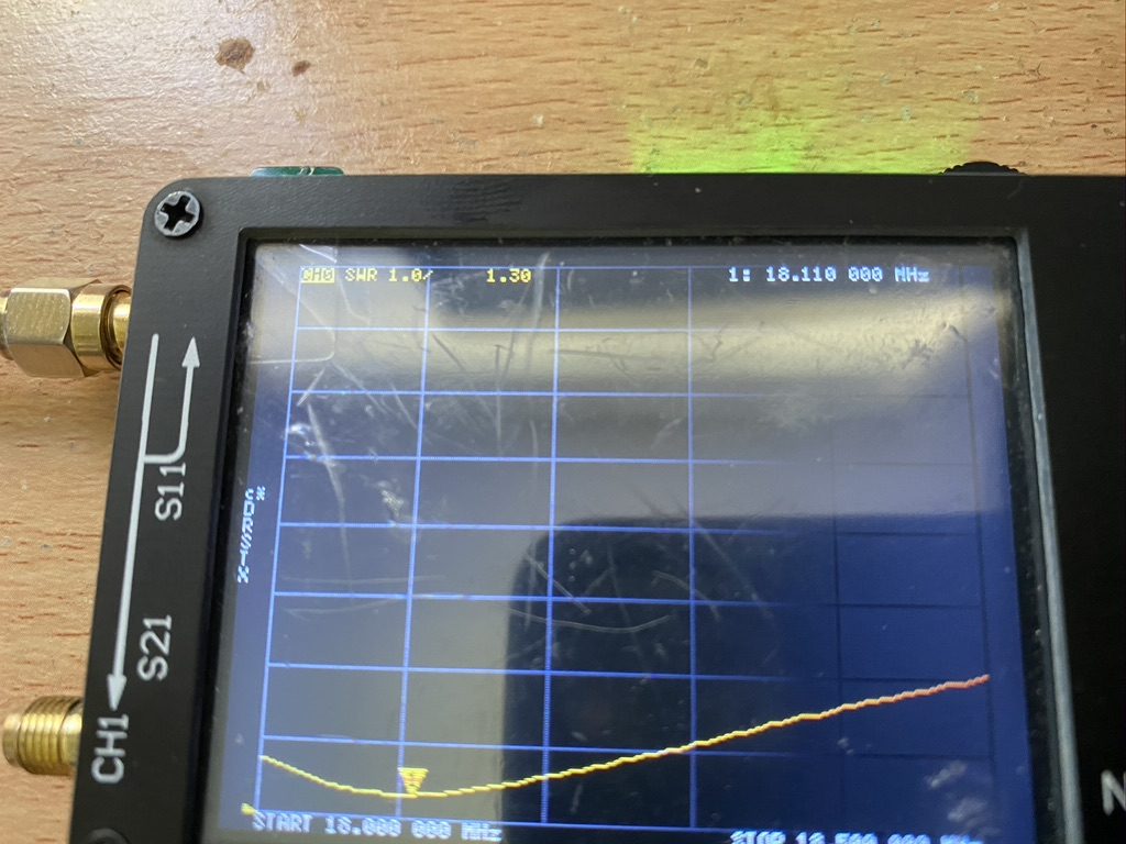
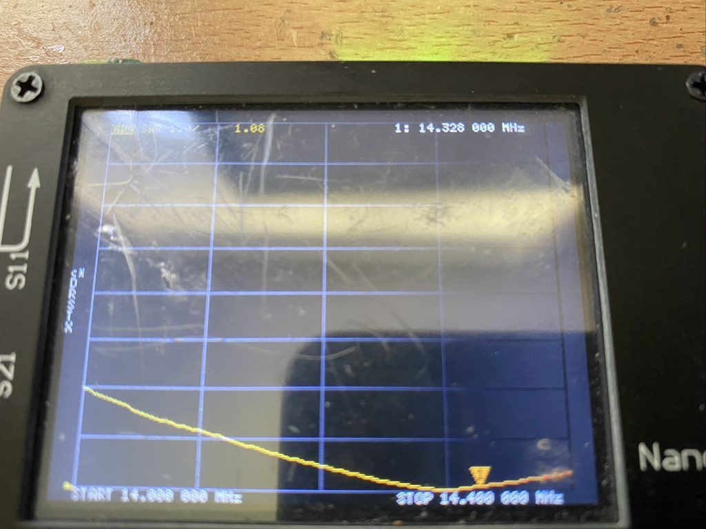
Amateur Radio Frequency Measurements
Meters
Mid Frequency (Mhz)
S.W.R.
40m
7.1
1.52
30m
10.115
1.21
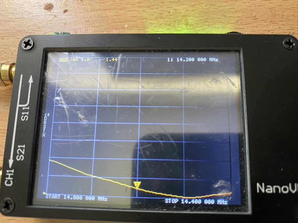
20m
14.2
1.53
17m
18.11
1.34
Amateur frequency readings after adjustments
So I am very satisified with my DX Commander – I may replace 30m with 80m, but at the moment I have plenty of frequencys and modes to work, even with 10W of power. Thank you Calum the DX Commander for this amazing antenna system !