As i have been doing more ‘re-arranging’ in the QTH, I thought I would revisit the snippet from the previous weeks posting on NOAA & METEOR decoding. I have evolved from ‘home brew’ antenna and tools on OS-X to fully automated and a specialist NOAA/METEOR antenna.
Hopefully by the end of the post, you will get a feel and and idea of where you would like to start or explore further !
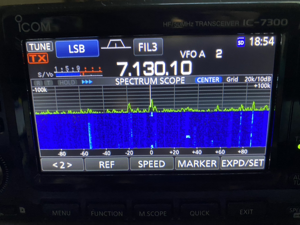
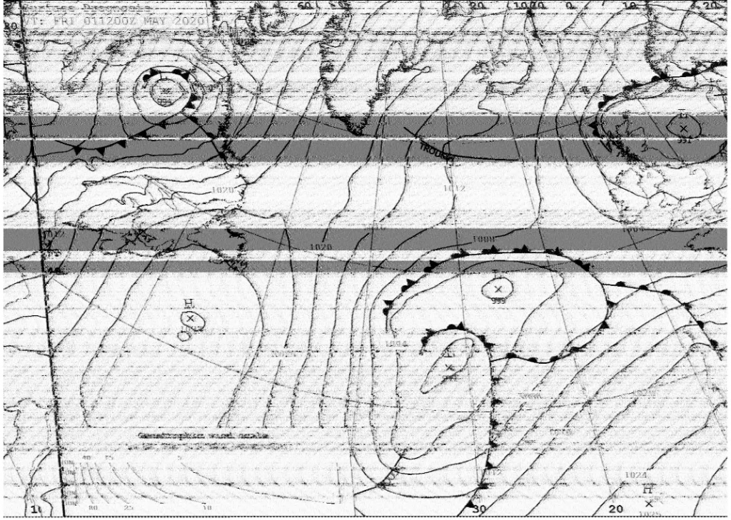
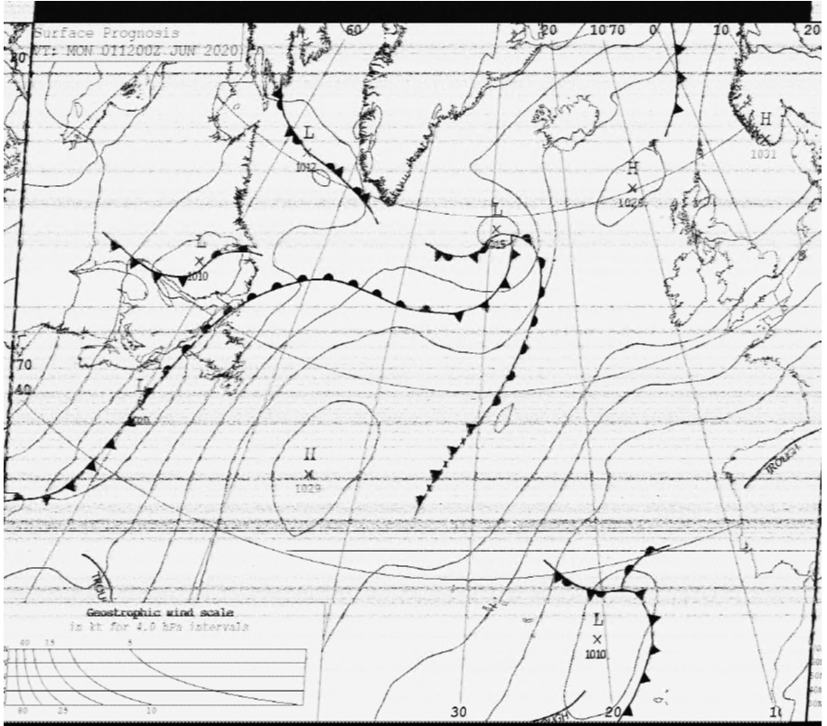
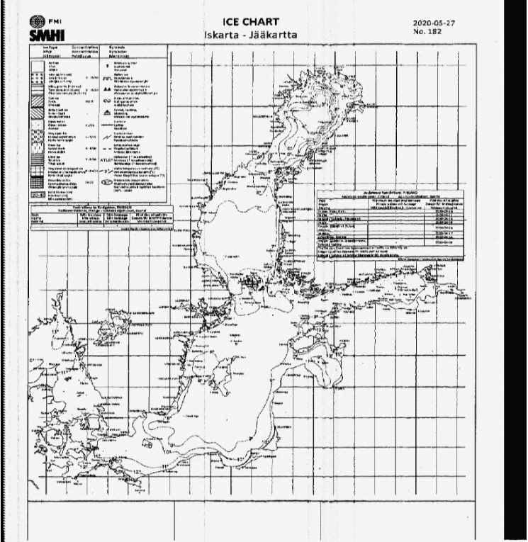
My first interest in weather and amateur radio came from receving Wefax images. I still do this as it complements and also gives me some idea of interference/reception issues as i can usually clearly see any issues in the fax.
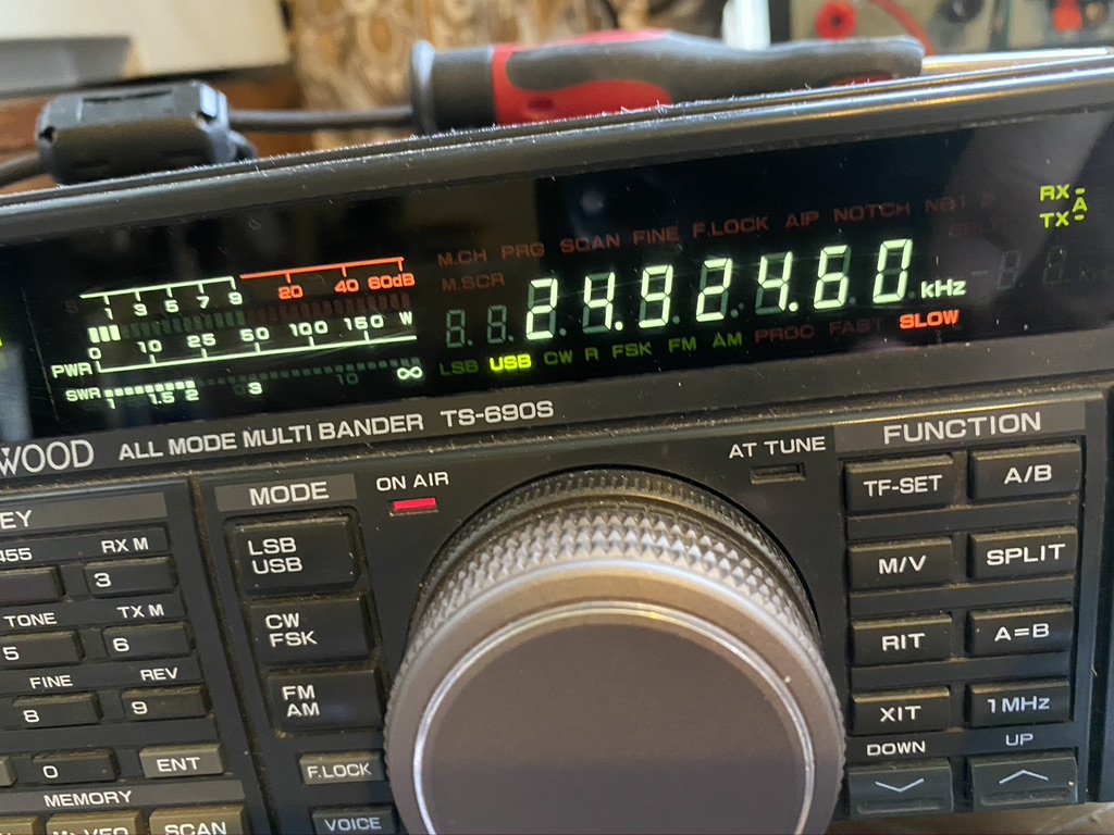
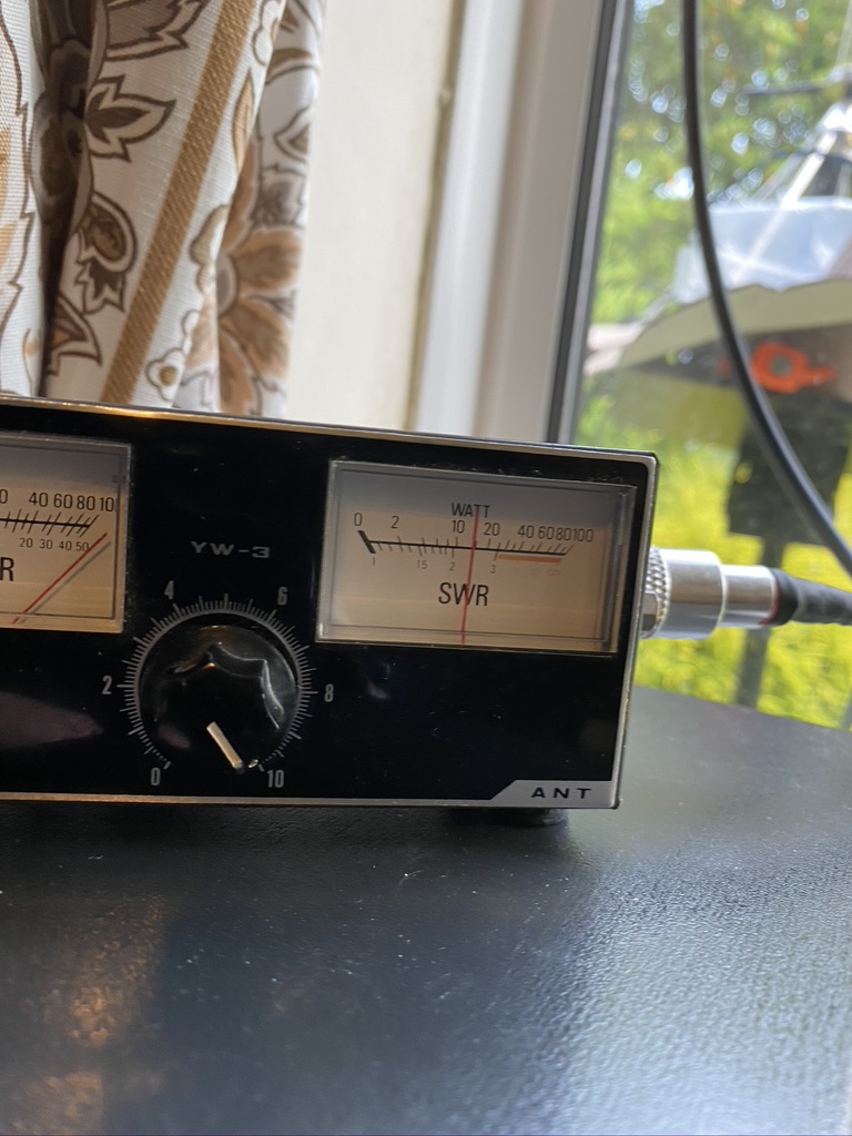
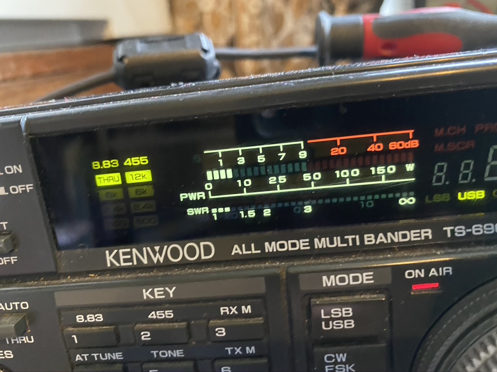
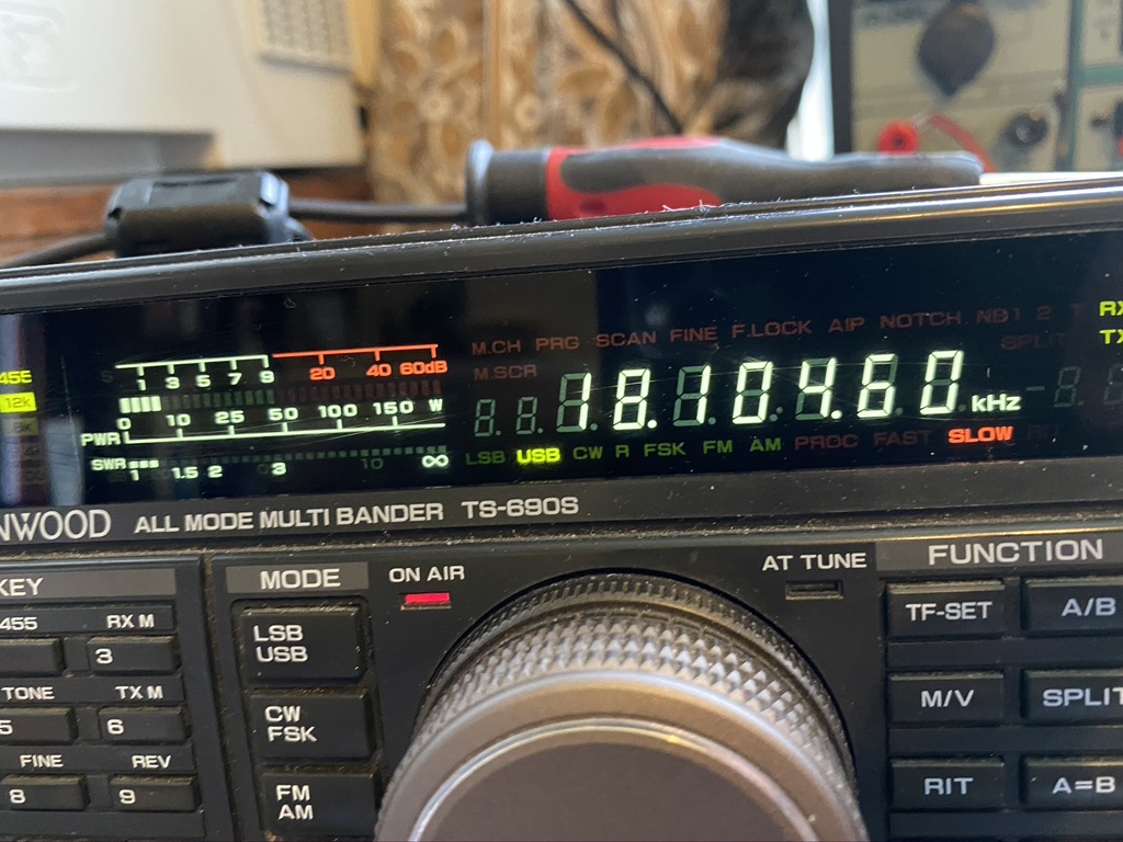
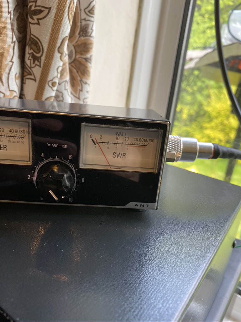
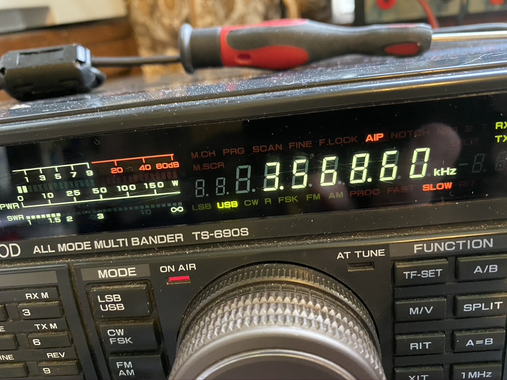
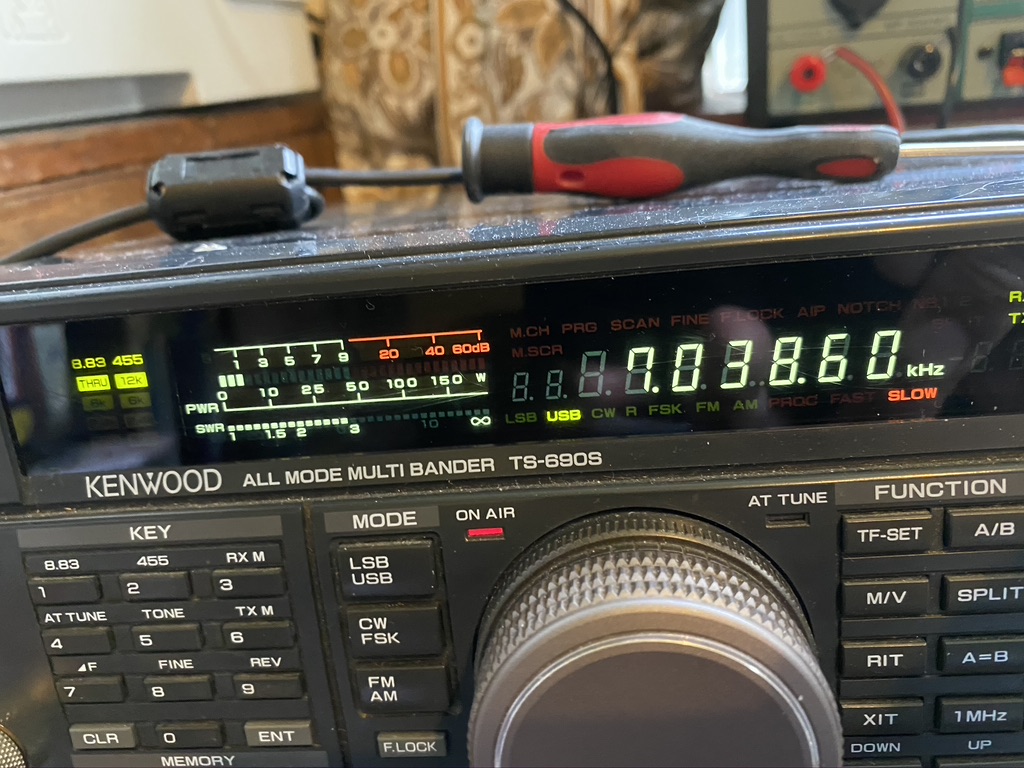
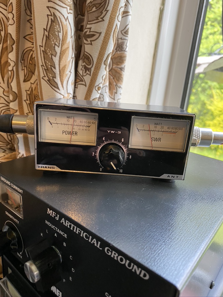
My favourtie charts are the UK ones available from on 4608 Khz trasmitted by Northwood.
<insert pic>
I find the detail and various types of graph really satisfying to read and decode via HF.
Following on, i found on youtube about a simple antenna and using SDR receiver to decode ‘NOAA’ satellites
The audience here is very clearly windows users, and whilst I have a Windows 10 machine for HF Digital modes, i wanted to keep the SDR seperate from that system.
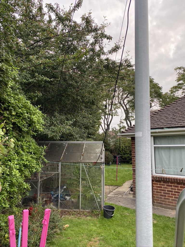
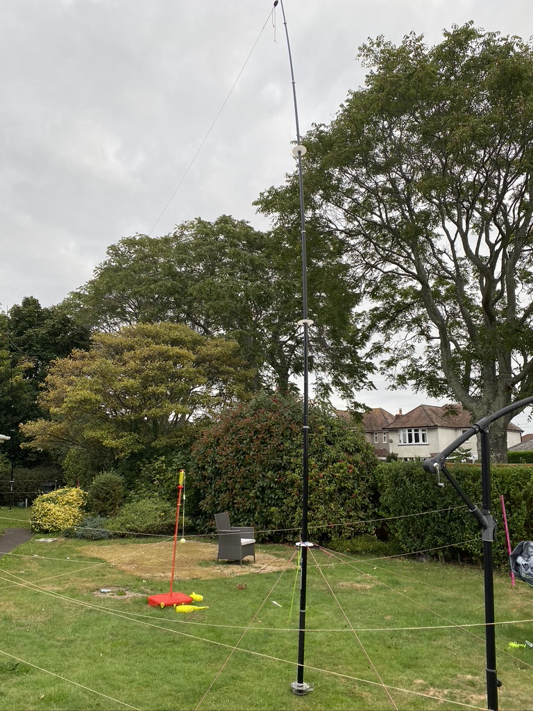
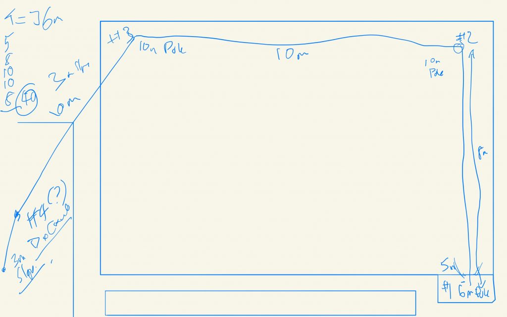
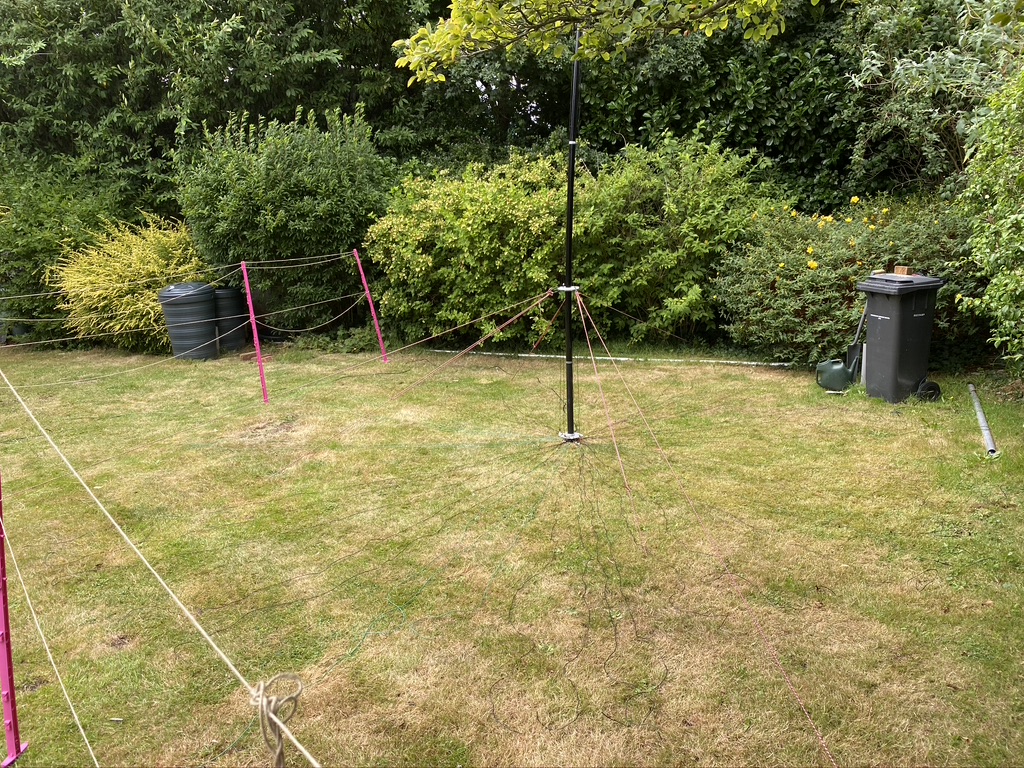
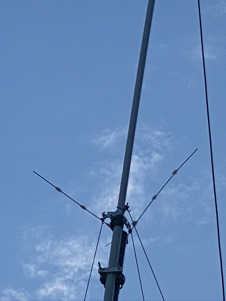
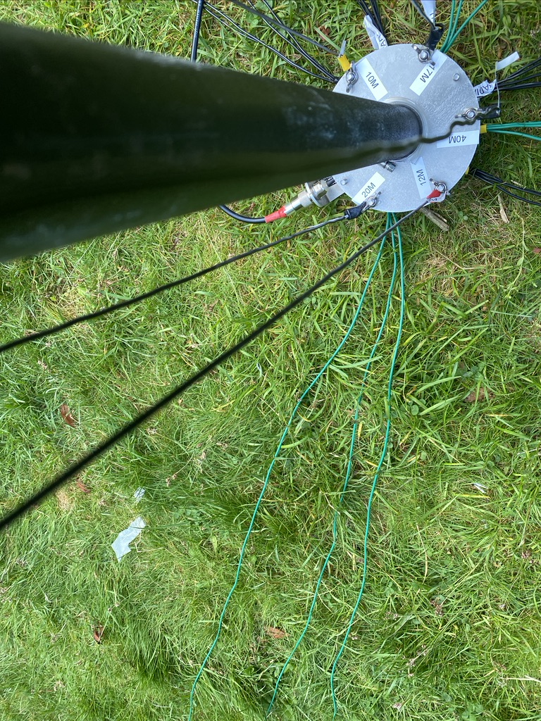
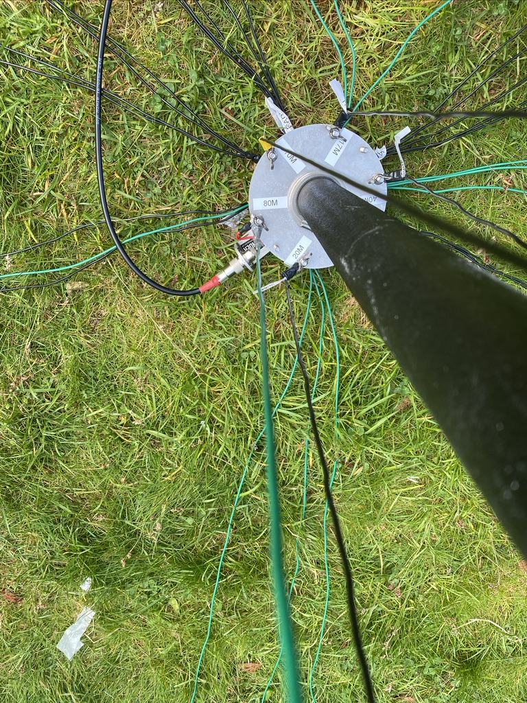
I built the antenna from bits I had around, although it did take up quite a bit of decent low-loss coax to get it up a reasonable height.

Get the antenna orientated well North-South effected the signals the most. Whilst heigh was important, gettign the polarization brought about the best results.
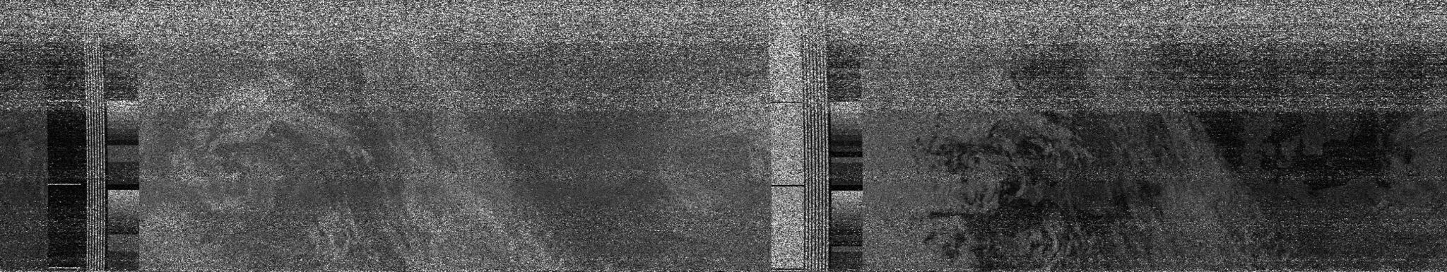
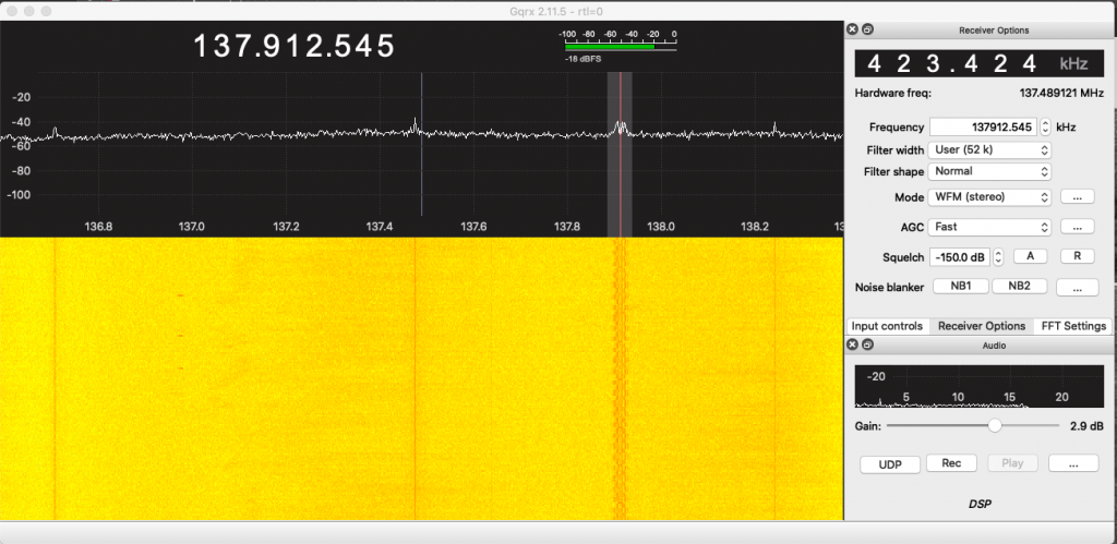
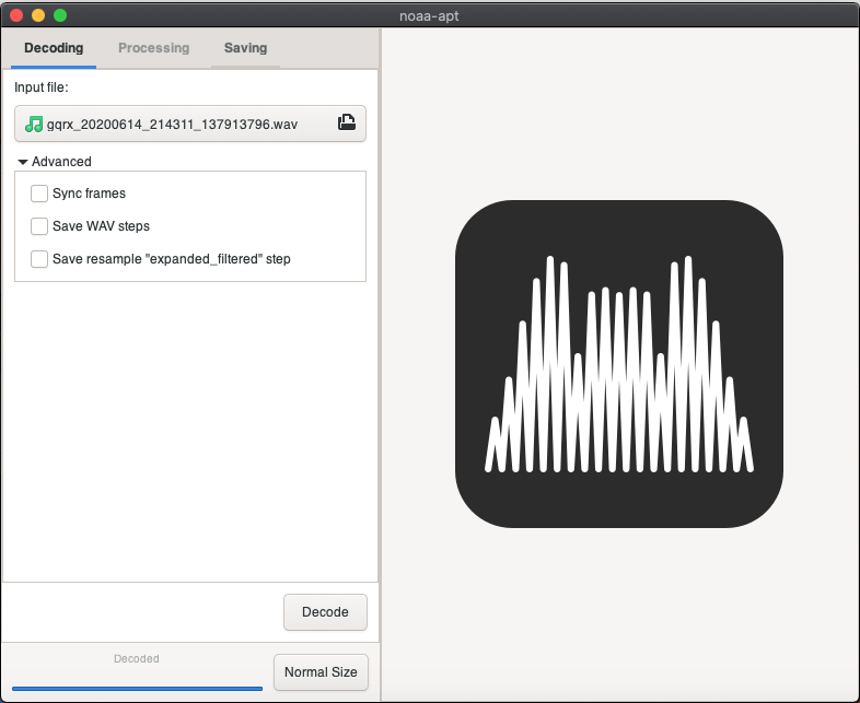
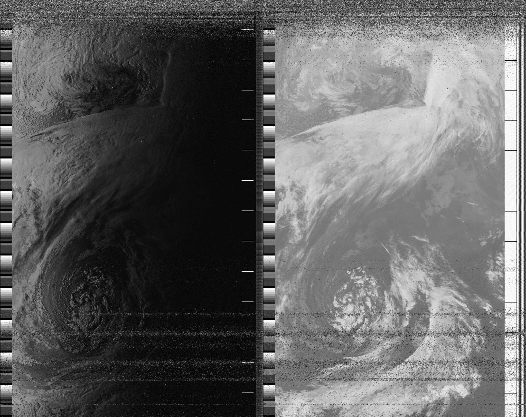
My first reception pics, whilst not amazing, really pleased me as the technology was at least working correctly. On a mac the missing component was being able to decode the ‘wavs’ to images, for this i used https://github.com/artlav/meteor_decoder which was easy enough to build via homebrew.
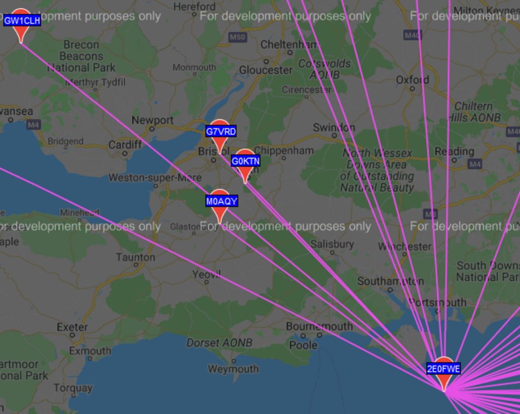
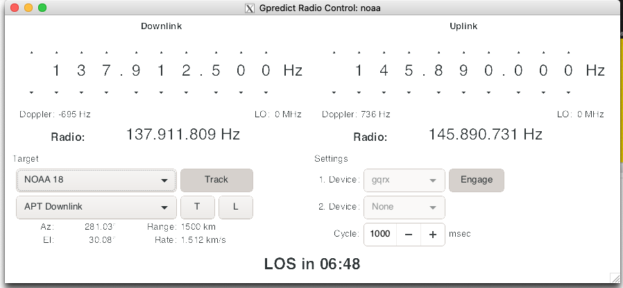
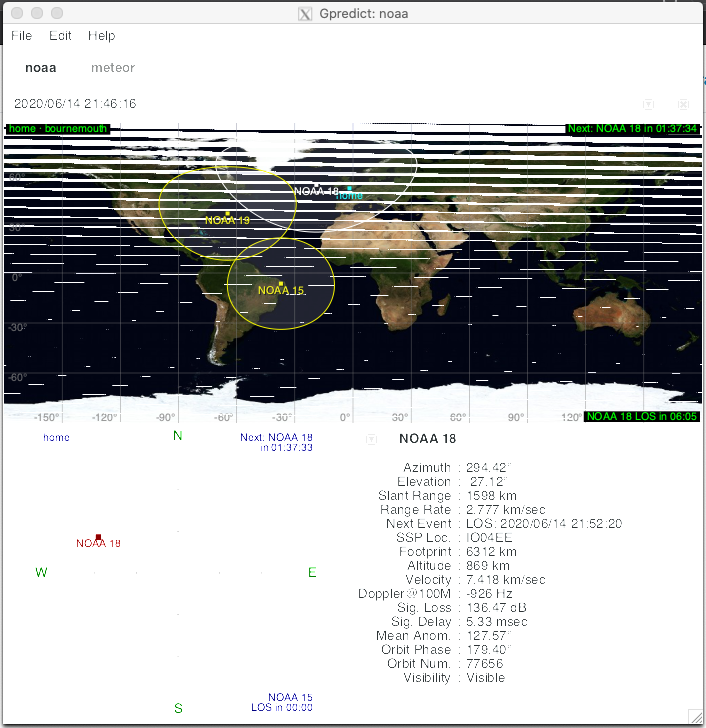
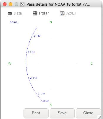
I monitored https://github.com/csete/gpredict where i could manually and getting the direct overpasses with the V antenna produced very good results.
I continued to do this for some weeks and built up my collection of NOAA pictures. I had still yet to sucssfully decode METEOR-2 as that was a digital signal and passing times were not in favour of a day-time working schedule.
We are still currently in a Covid-19 situation as time of writing and since Feburary 2020 here in the UK, so whilst many designs of NOAA antennas exist, I very much avoid supermarkets/large DIY outlets,etc unless absolutely essential, and usually for ‘click and collect; (Order online, pick u pin store, no wandering around).
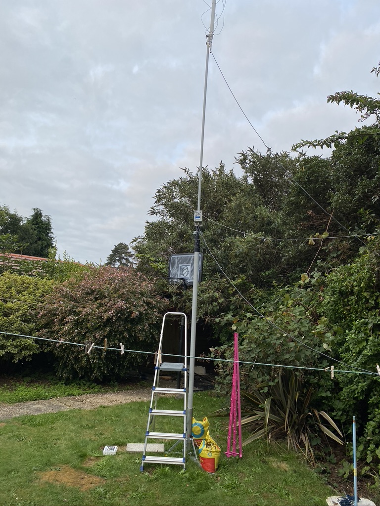
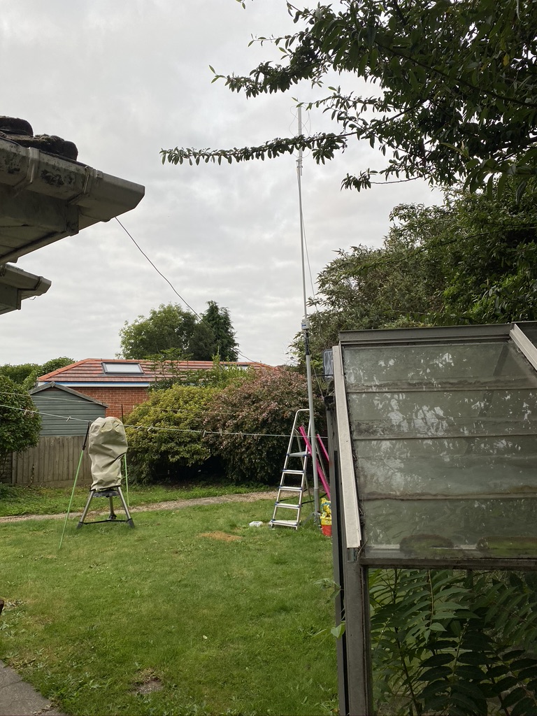
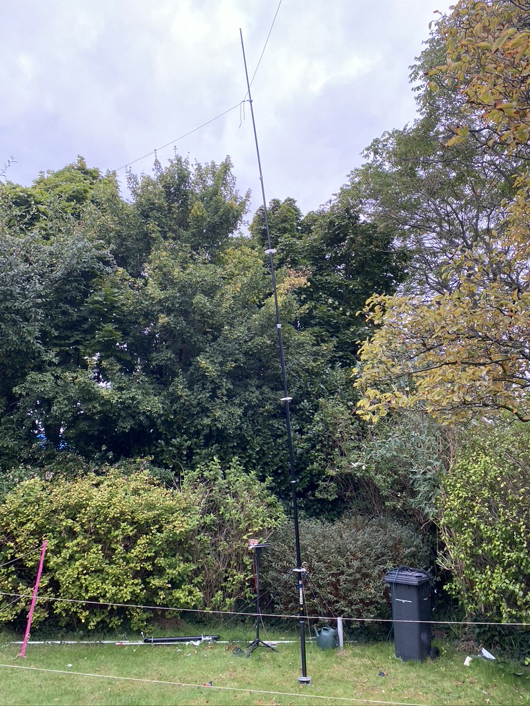
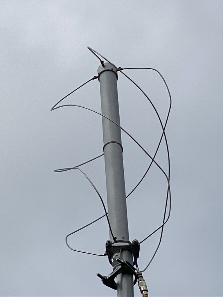
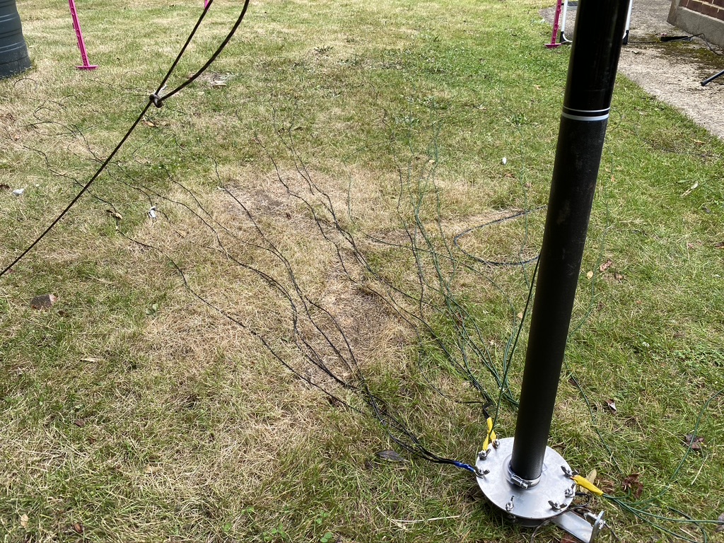
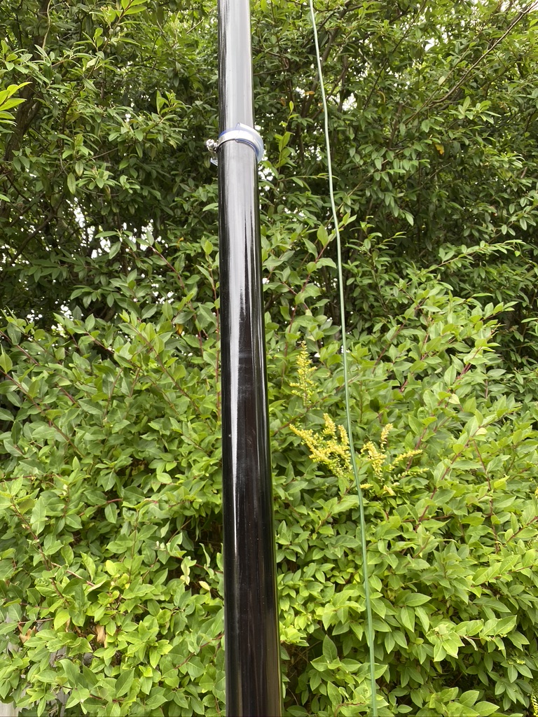
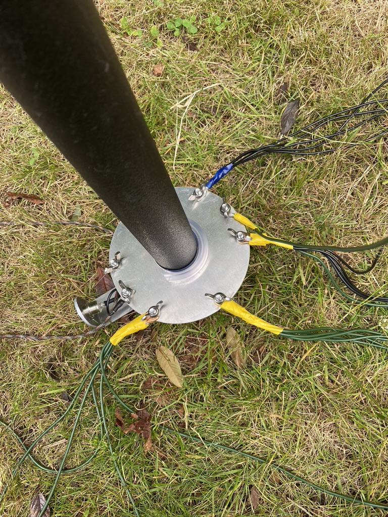
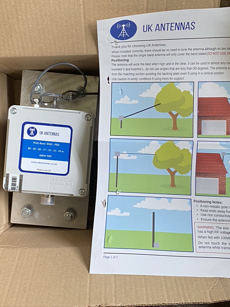
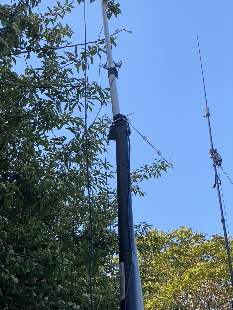
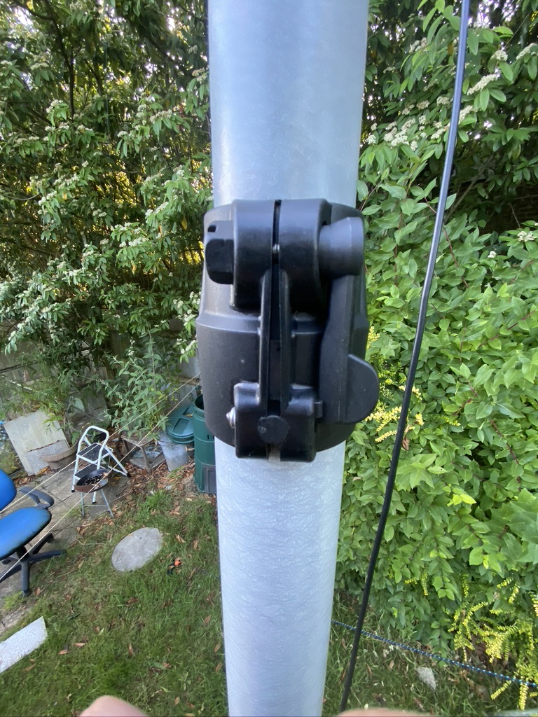
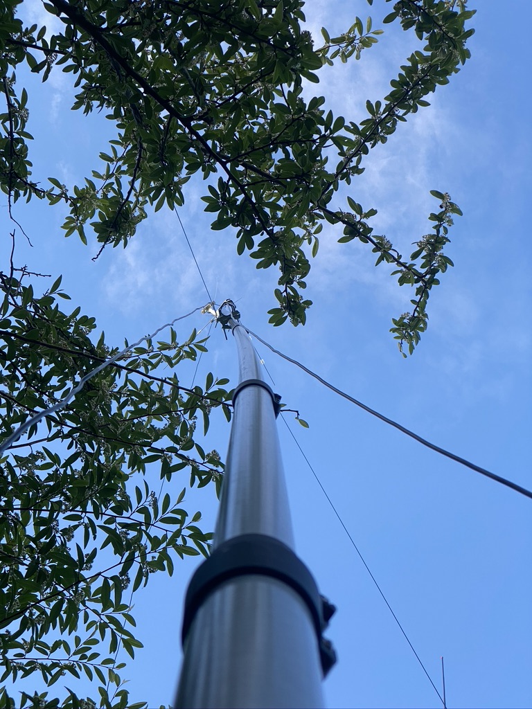
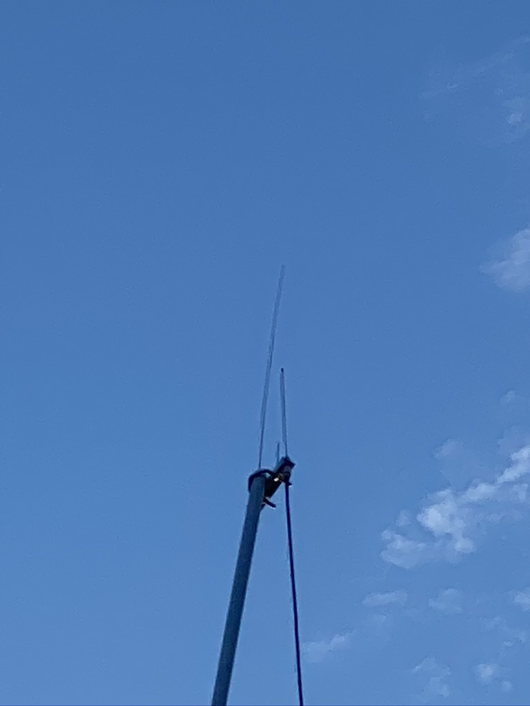
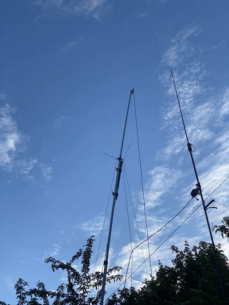
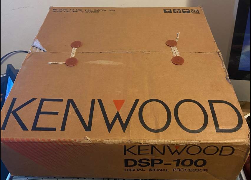
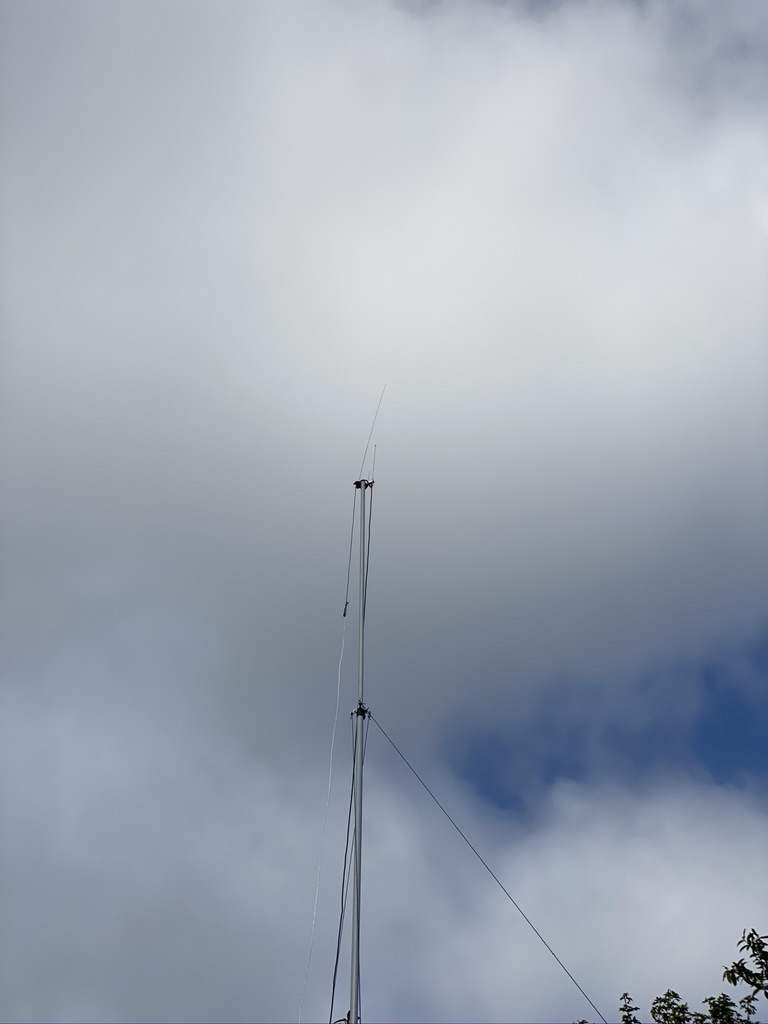
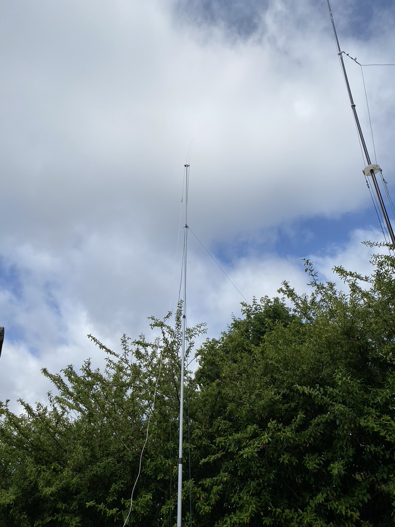
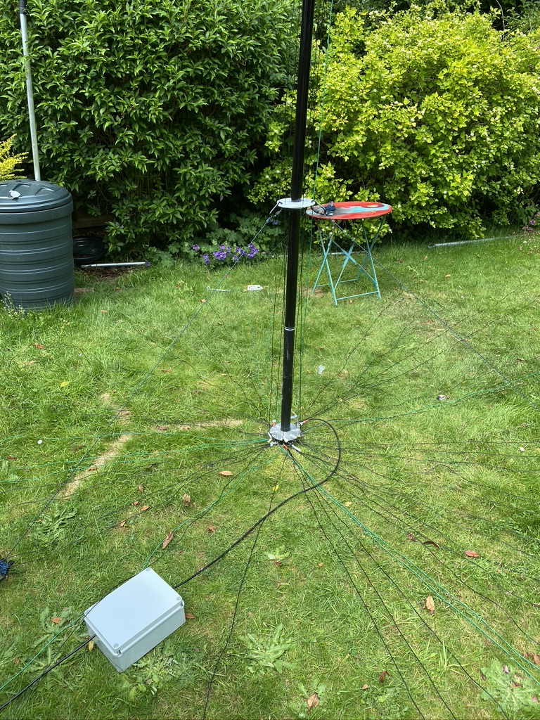
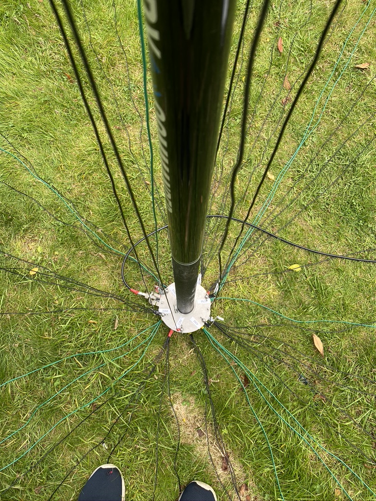
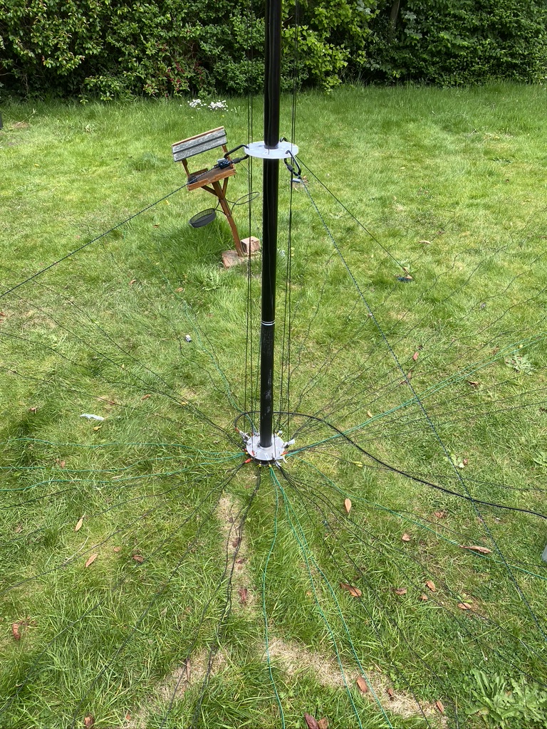
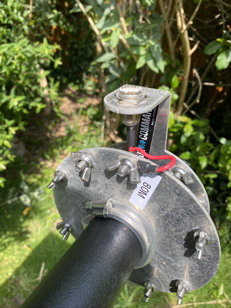
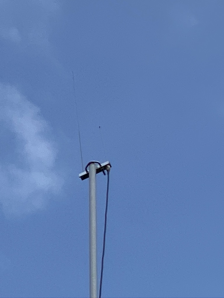
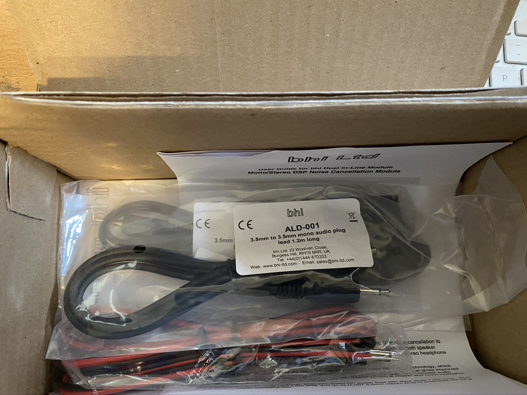
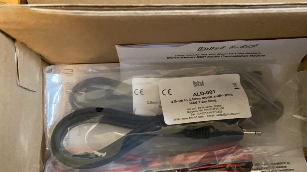
With that in mind i reached out to Dr Google to find pre-made NOAA antennas. This thread on reddit https://www.reddit.com/r/RTLSDR/comments/8biful/is_there_any_place_to_buy_a_decent_137_mhz_noaa/ gave me the link to the National RF antena http://www.nationalrf.com/satellite-tenna.htm. These are built to order, so there is a wait time, but it is well worth it. I was kept fully informed of progress and still had my V antenna to keep me going. Packaging from the US was fantastic, very well protected and assembly was very easy. I did have to get some PVC pipe to use a ‘mount’ to the mast and a BNC to SO39 adaptor, but these are very easy to come by and have no real loss to the to the receive-only antenna.
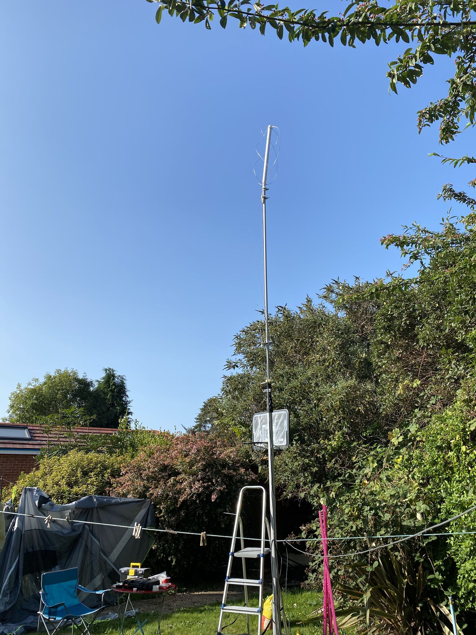
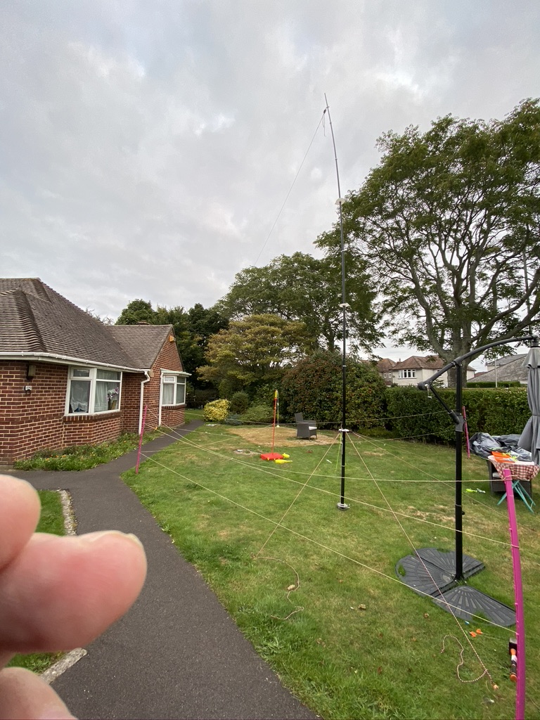
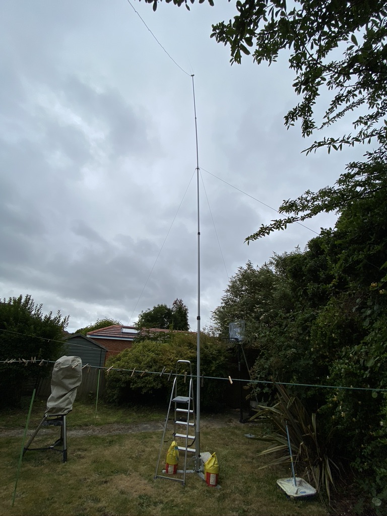
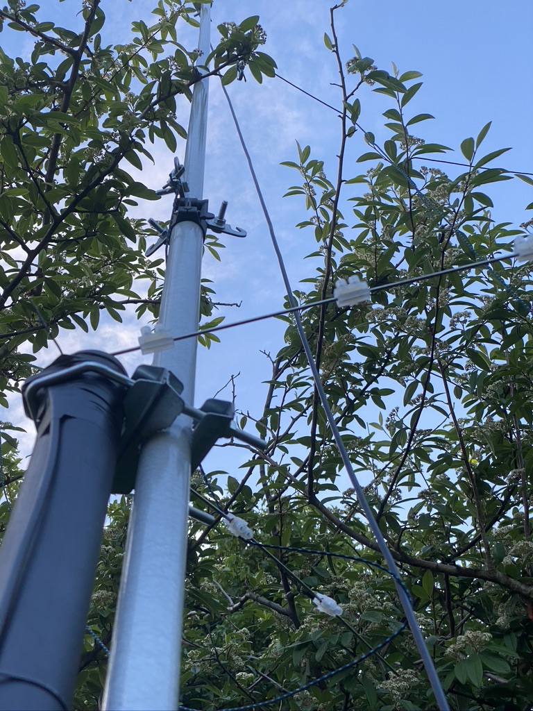
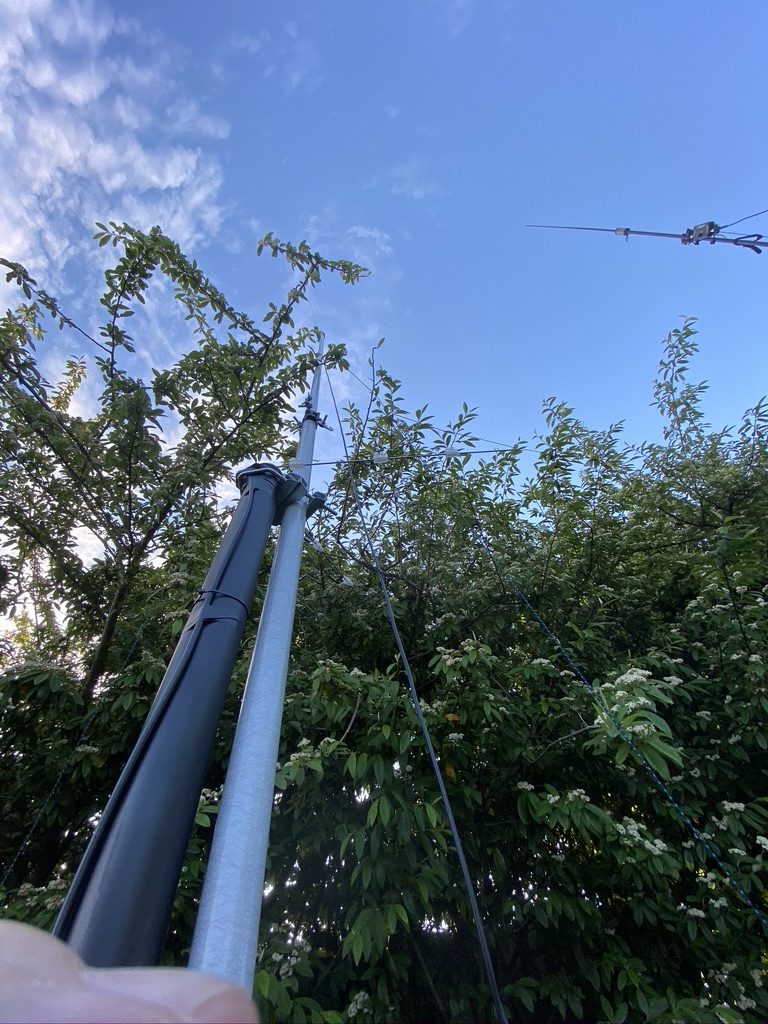
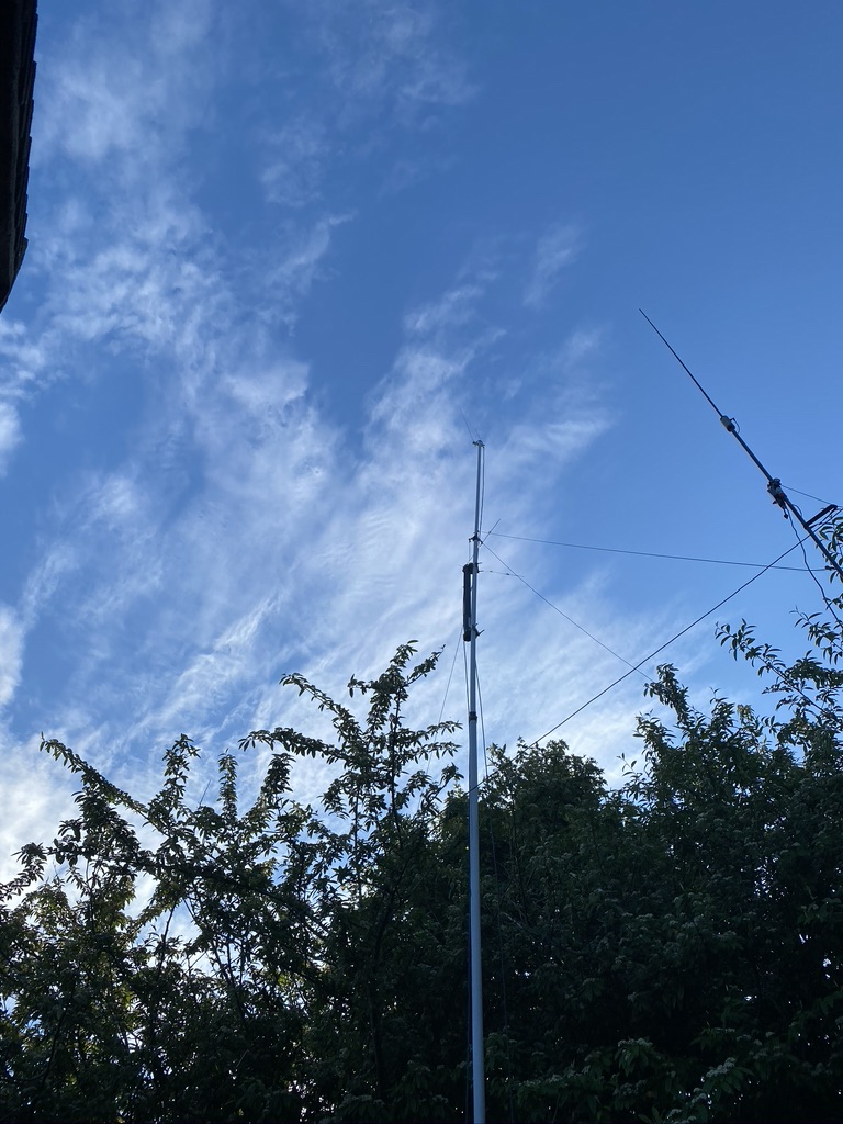
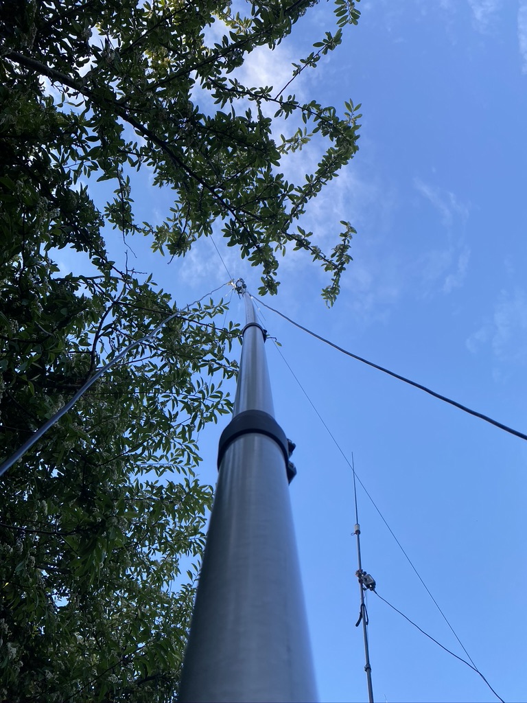
I used my VHF mast, replacing my 2m/70cm antenna with the NOAA antenna. Whilst the mast can go up 30ft, it requires careful observation and maintenance to keep that high. Instead, i opoted for just over roof height of 2m and a clear line of sight to the horizion.
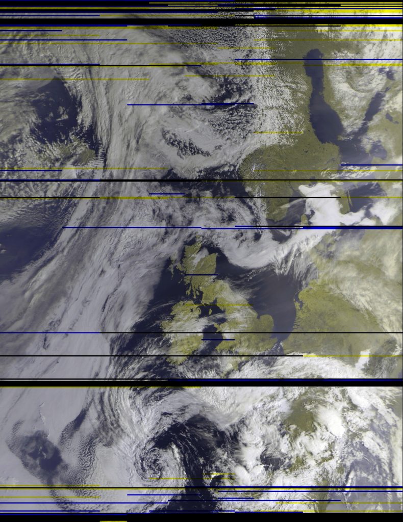
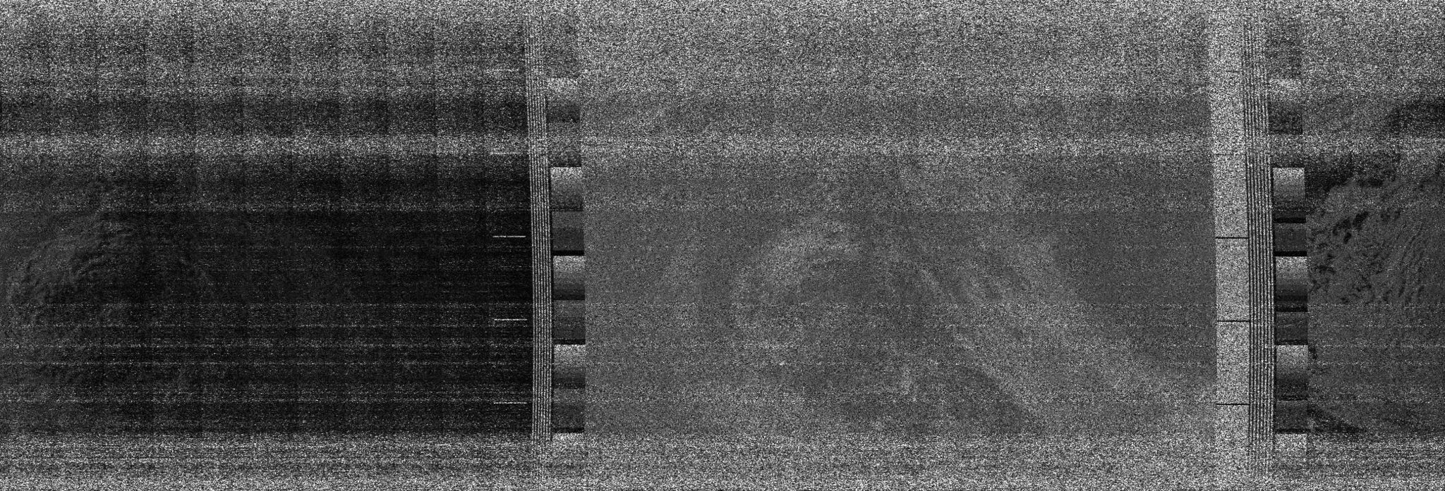
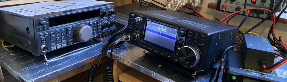
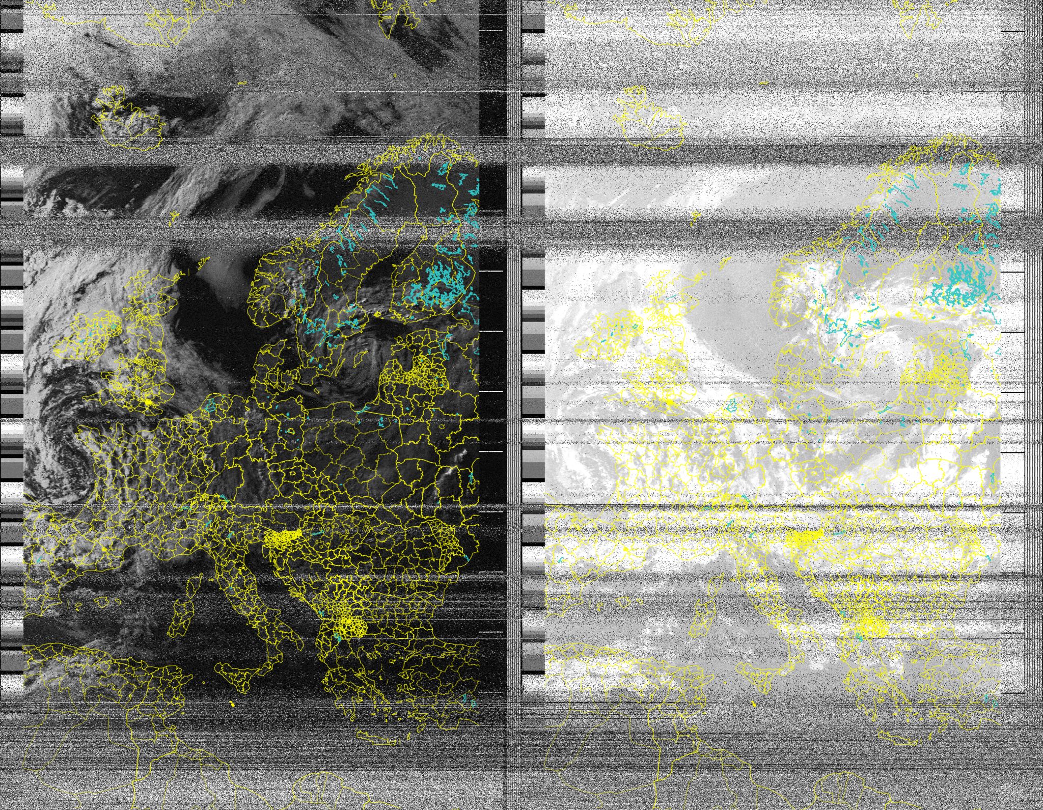
The antenna greatly improved the reception of signals as later pictures show, albeit I am still using the mac and GQRX and a simple SDR at this time.
I continued with the Mac, SDR, GQRX, Gpredict and meteor decode for quite some time, but as i got busier with work i had no time even to manually decode, as much as I enjoyed it !
The next step was to further improve reception and automate. This was accomplished by purchasing filters and amplifiers specifically for the NOAA RCPT frequencys in VHF and then re-cycling a Raspberry PI3.
The original video gives the necessary filters, but for a shortlist here they are
NooElec SAWbird+ NOAA
Flamingo+ FM – Broadcast FM Bandstop Filter v2
NooElec NESDR SMArTee XTR SDR
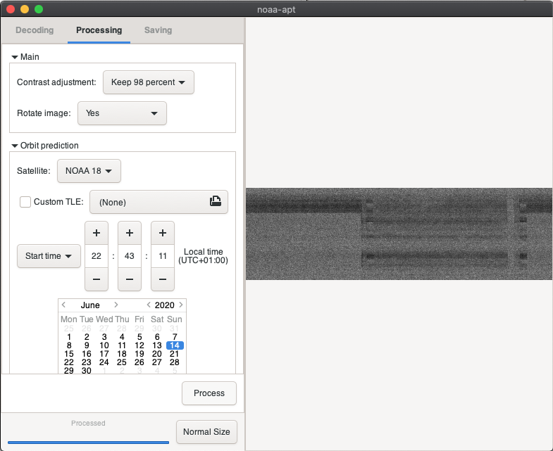
As I wanted to automate this and provide a simple way to just look at the received images i used https://github.com/reynico/raspberry-noaa repo, which was by far the easiest package to setup and use on my Raspberry pi.
If your not familar with linux/unix this could be a bit of a blocker, as you do need to manually edit some configuration files, so being familary with standard OS commands and a text editor like ‘vi’ i would say are the ‘essentials’ to being able to use this. I dont mind saying i had to refresh my memory on how ‘at’ the scheduling tool worked having always be a ‘cron’ person.
In practice once setup, there is very little to do, but what i have done is to alias ‘atq’ to make the list of tasks in date order.
alias atq=’atq | sort -k 6n -k 3M -k 4n -k 5 -k 7 -k 1′
This makes reading the scans far easier and i can still use gpredict on my mac to see which ones are the most interest to me. The software will automate, and try, every scan, but if rtl_sdre is already running, will not be able to run. In that case its always useful to ‘prune’ out the less interesting or scans which will suffer the greatest interference. I always priortize Meteor passes over NOAA passes as Meteor decodes seem to be. a maximum of 2 per day. This is easily managed by the combination of ‘at -c <job>’ to ensure no duplicate tasks are running.
I have been running on a PI now for just over 2 weeks, and as part of the QTH tidy up am moving the Pi from a ‘desk’ to a shelf where it will be safe and less prone to me knocking the amplifier and notch filter out.
I am amazed by all the scans i can receive and thoroughly enjoy understanding how it works, and being a recipient to the amazing images that both the NOAA and Meteor satellite send for free !
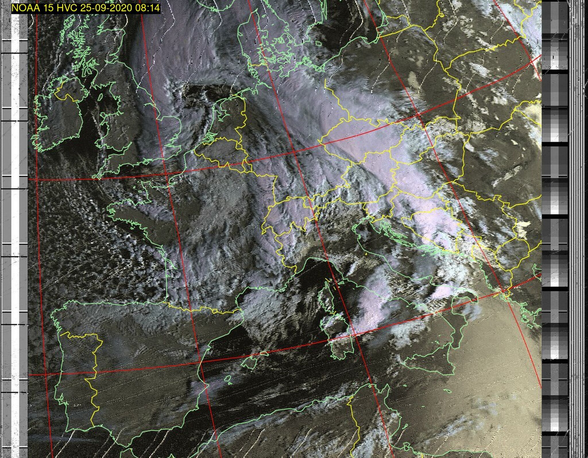

Overall i can say that investigating the weather satellites has really complemented by amateur radio activities. I’ve learned how important good antenna design is by the progression from a simple V dipole to a professionally built helical antenna, and the use of amplifiers, band filters and the right SDR unit to use for the hardware available.
I have since purchased 2*Pi4 as I would like to use a Raspberry PI more with the other SDR’s i have (Airspy, HackRF) to learn to program and enjoy the decoding more. Building good antennas will only help what i need for future amateur broadcasts as well.
Overall, i can really strongly recommend decoding weather satellites, if anything you get amazing images of your QTH and combined with WeFAX you can make your own weather predictions !