Was feeling a bit under the weather (aka sick) this weekend, nothing serious, but not well enough to think that working outside in the cold would help me feel any better.
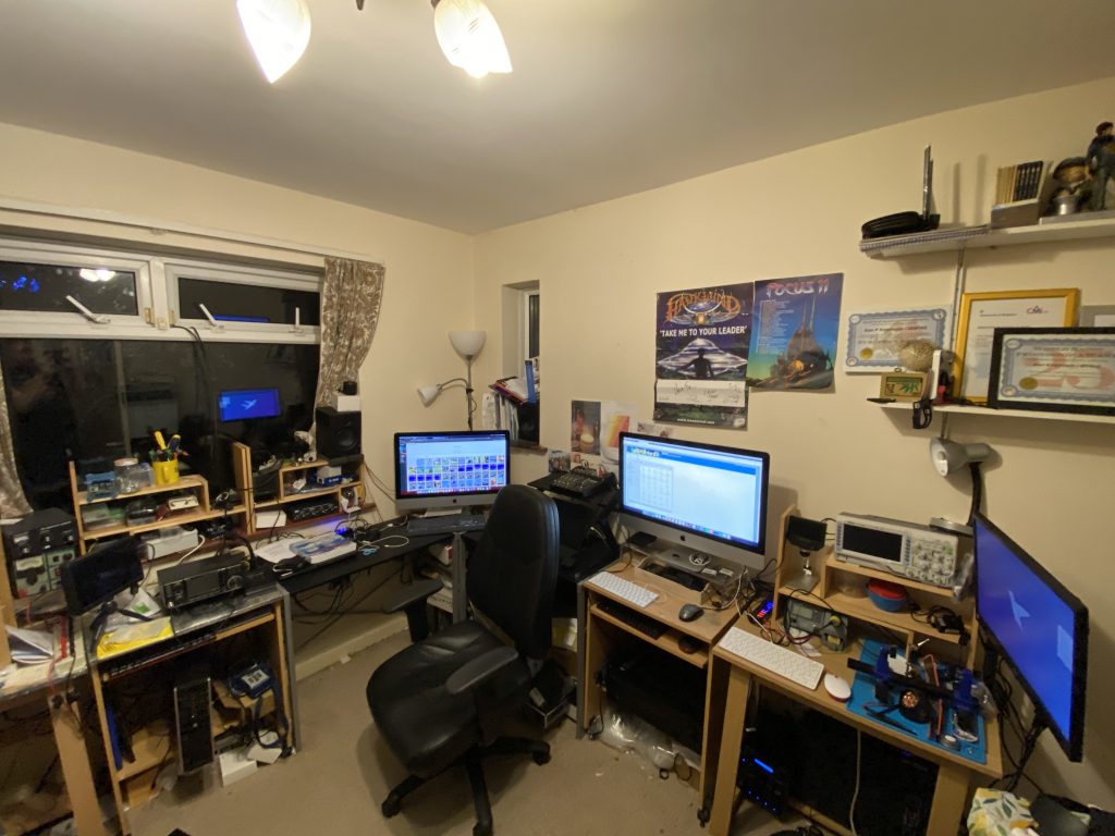
Undettered I looked at what can be done in the shack (aka my home-office) and there is always plenty to do ! With the Nebula build the tidyness got a big neglected and mutliple things stated but not really progressed in a considerable way.
If any of you rememeber, or care to look back at earlier posts, you can see my ‘shack’ has really evolved. All the synths have move next door to their own mixing desk and imac just for running music related apps, so that has allowed me to fully expand one side of the room with other computer equipment
I am using a smaller ZMX862 mixer into a Yamaha A-S201. I take the line-out from the dual-line BHI noise canceller into the mixer, then into the amp. The sound quality is amazing (should record something when i get time). The down side to this setup is the absence of an integral USB interface that is on the larger mixing desk now used for the synths. To overcome this I’ve ordered a Behringer UCA222 USB Audio interface which will allow me to both record and take sound from the mac (why did they ever remove the optical line out ?!?!).
I’ve also setup my build bench used for kits and linux raspberry pis & servers to faciliate the use of the various SDR’s I have. My aim is to have a number of SDRs setup, ideally I will a full band SDR available over the internet. OpenWebRX is available from github whilst based on Python 2, looks good for the job for now.
A slightly tidier shack, more to be done, but progress !
I also had a ‘play’ on other frequencies over the weekend and was amazed to make contacts on the 10m band. I had always thought that 28Mhz would be pretty much line of sight, so was amazed to make make contacts in Israel and Spain !
FT8 Contacts on 10m – Spain, Israel and England
Was making endless contacts on 80, 40 and 30m over the weekend as my QRZ page will show !
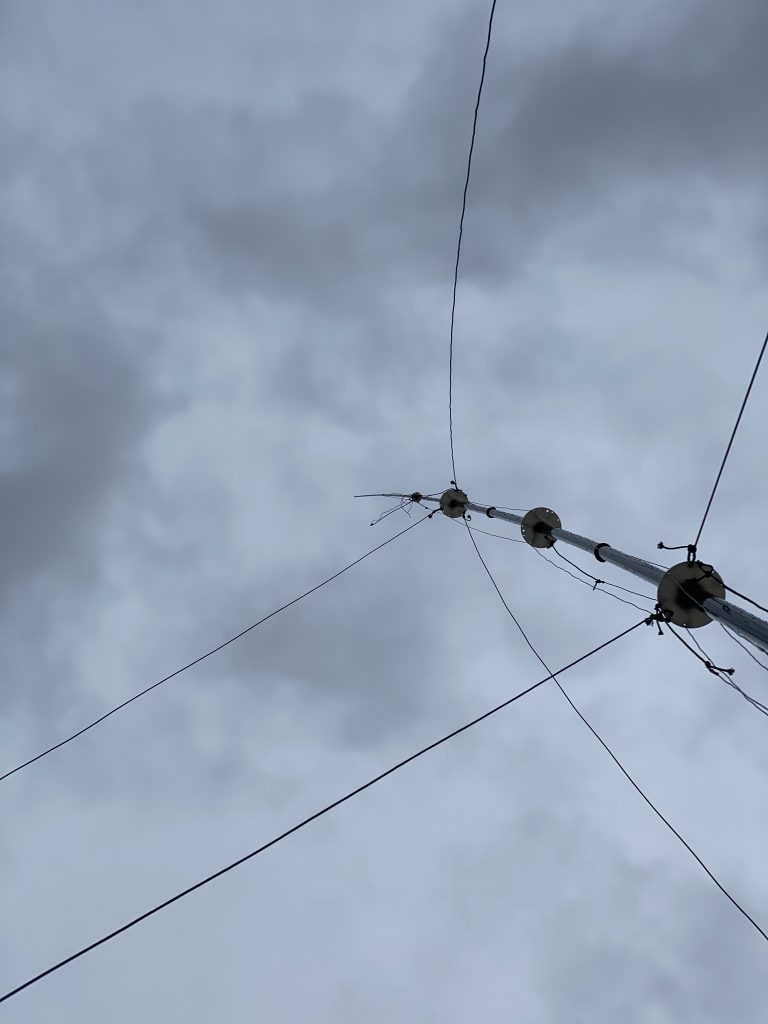
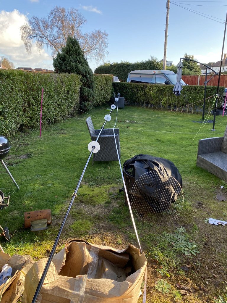
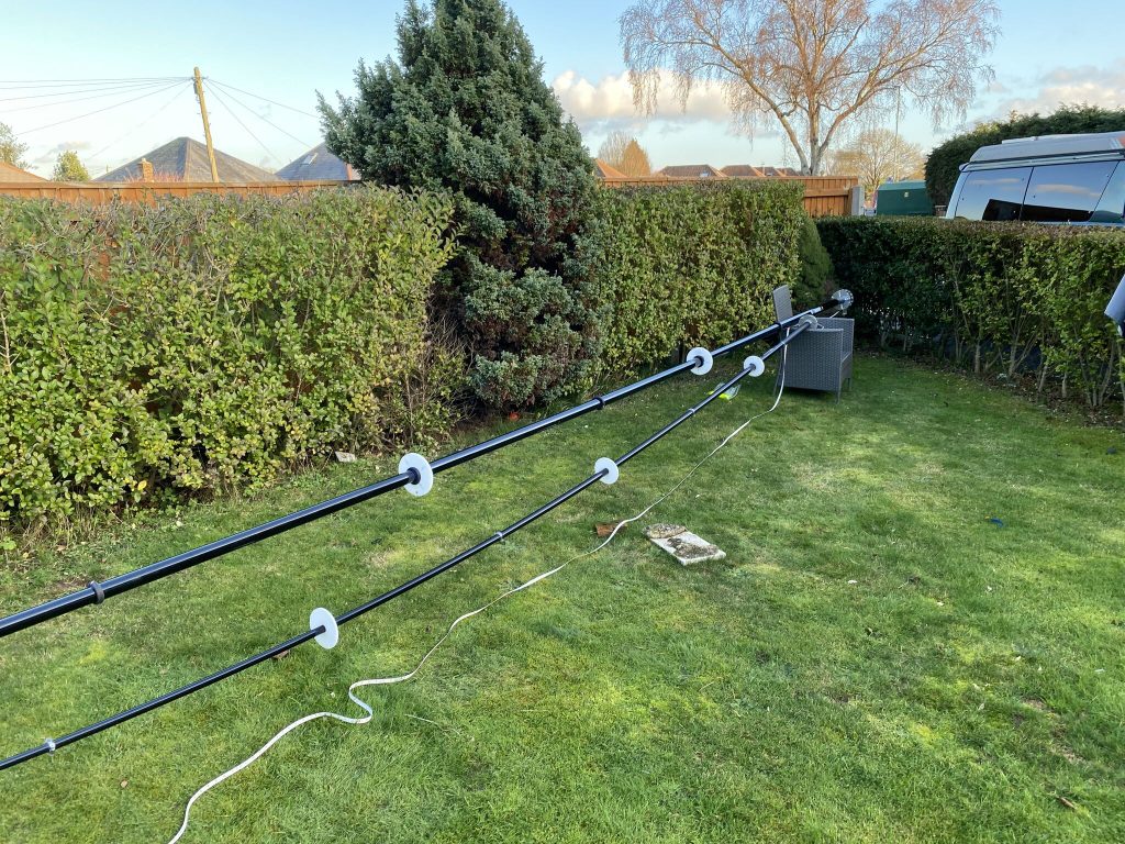
Whilst taking the doggo out for a walk i noticed the 80m wire was ‘flapping’ somewhat, and on closer inspection, 20m wire had snapped completely ! I had probably done these too tightly, so for now have taken the mast down. With my health not at the best today, i just got the antenna down so i could inspect it more closely, thankfully 20m had just snaped (easily replaced) and a clip-carabina out of place on 80m had made it very loose.
I still have some fetttling to do on all the bands, so this will provide a good opputnity to get the vertical wires installed better thant he initial delviery.
flappy 80
snapped 20
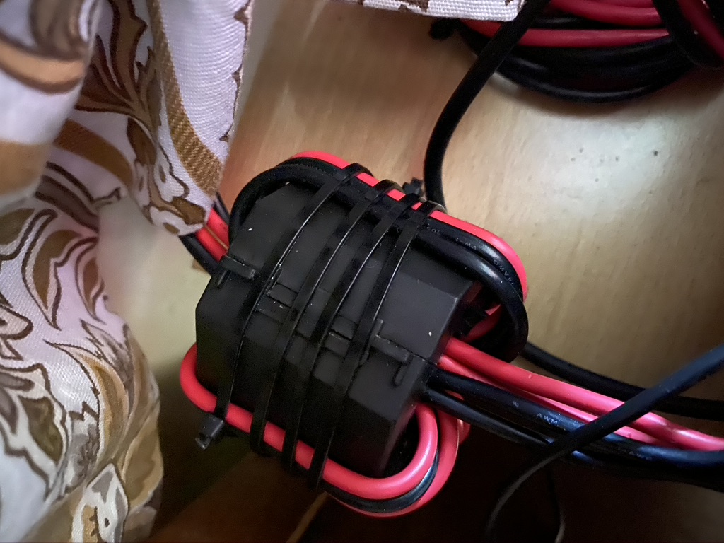
nebula wires damage
I’m hoping i will feel somewhat better next week and can continue my exterior projects, esp the UHF/VHF 2m/70cm yagi, but will get the Nebula back up again as soon as possible, weather and my health permitting !
It has been a lovely sunny down here in Bournemouth and have been able to take full advantage of the good weather by getting on with assembling and tidying the gardens.
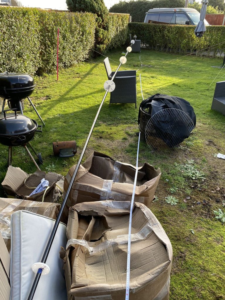
First off i set about extending the Nebula as far as I could on my own. With much twist I managed to get it to 17m32cm, which is what the docs say is ok to use.
DX Commander Nebula – 17m32cm
I dont mind saying it took me a few times to get the antenna out fully, the first attempt with trying to get it to lock from the bottom-most sections didnt work out, so i put it all back down, then carefully took out the furthest (top) sections carefull and locked each section. There is a fair amount of flex, but I’m stil careful as the top looksl like it could snap if careless exertion took place.
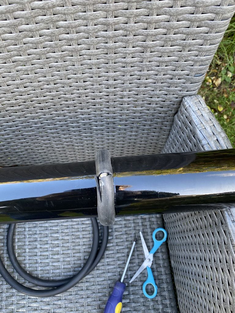
Once extended, i set about putting electrical tape on each joint of the mast, to give additonal support and minimize any tension scratching from the jubilee clips.
Electrical tape was appliedto each joint (some had to be corrected, but mostly ok)
with the mast now ready for the plates, i headed back in and started work on those.
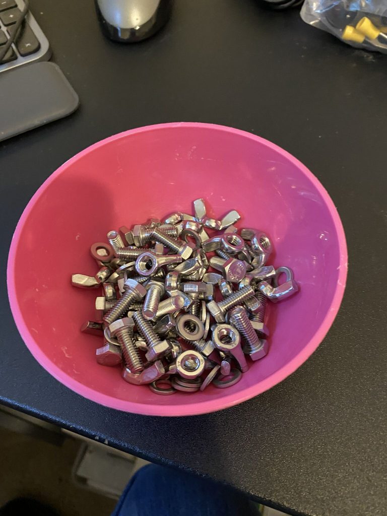
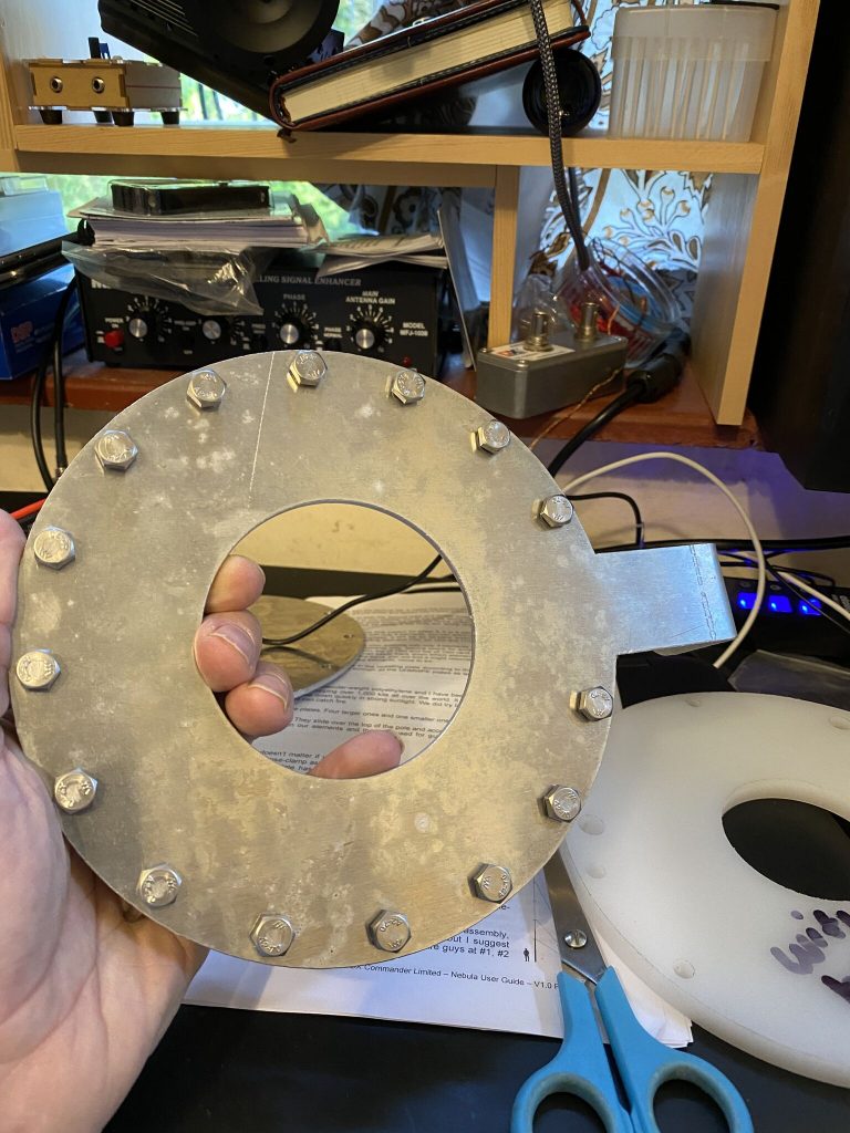
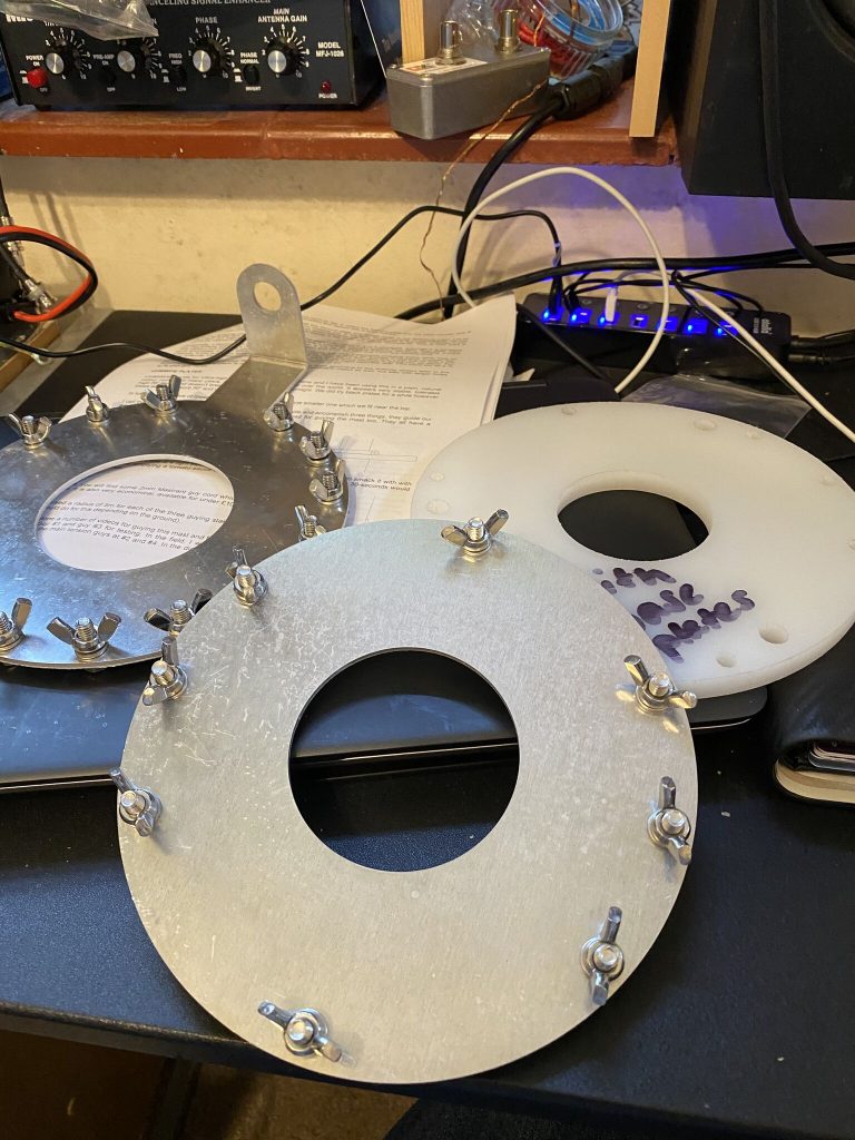
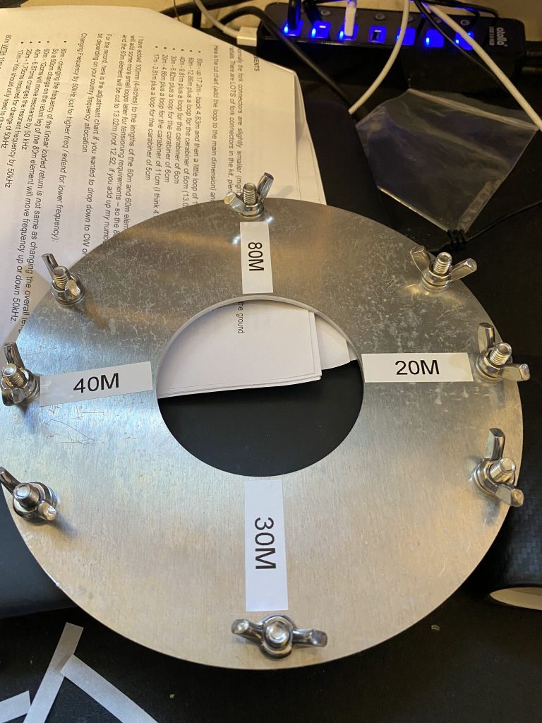
bolts, washers and wings
getting the alingment
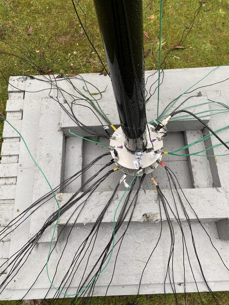
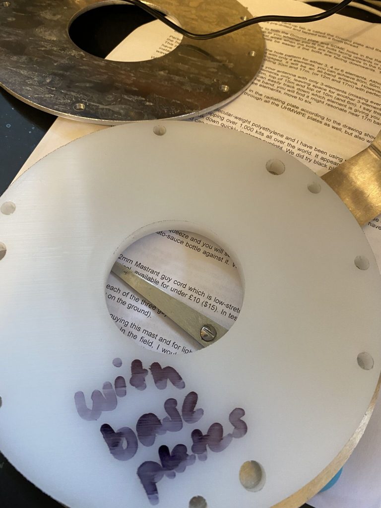
impressive amount of radial connections
and finally the element plate
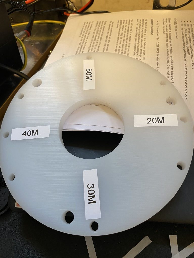
making up the radial and element plates
Building the radial and element plates was straight forward. The bolts, washers and wingnuts fitted perfectly with little or no resistance going into their thread – good manufaturing process there. The plates themselves look great and built to last. They are considerably bigger than the ‘classic’ plates, the amount of radial mounting points is great – and its those raidals which really helpin with the direction and ability to ‘push’ the transmission out.
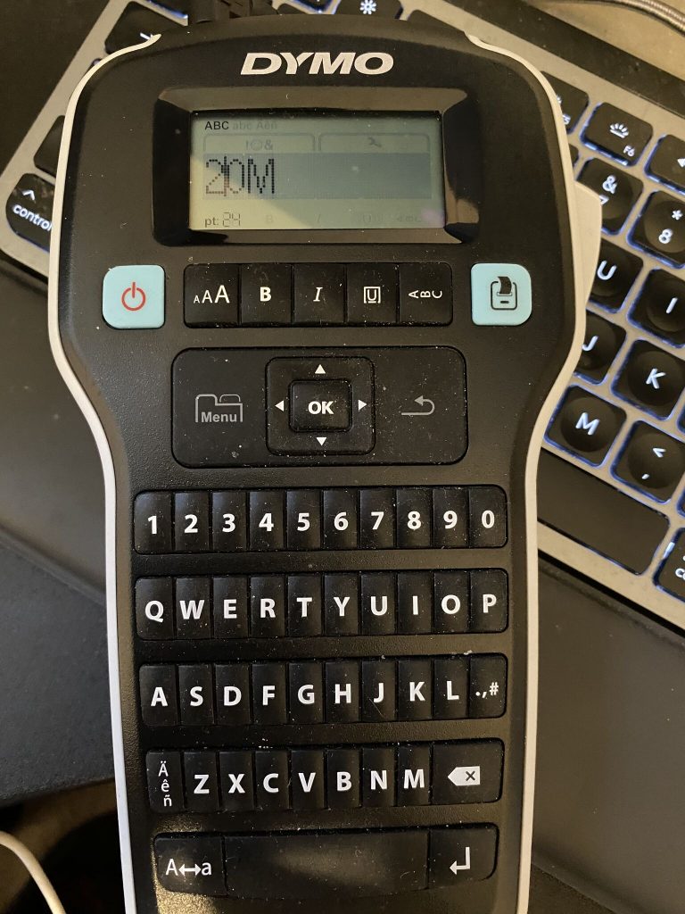
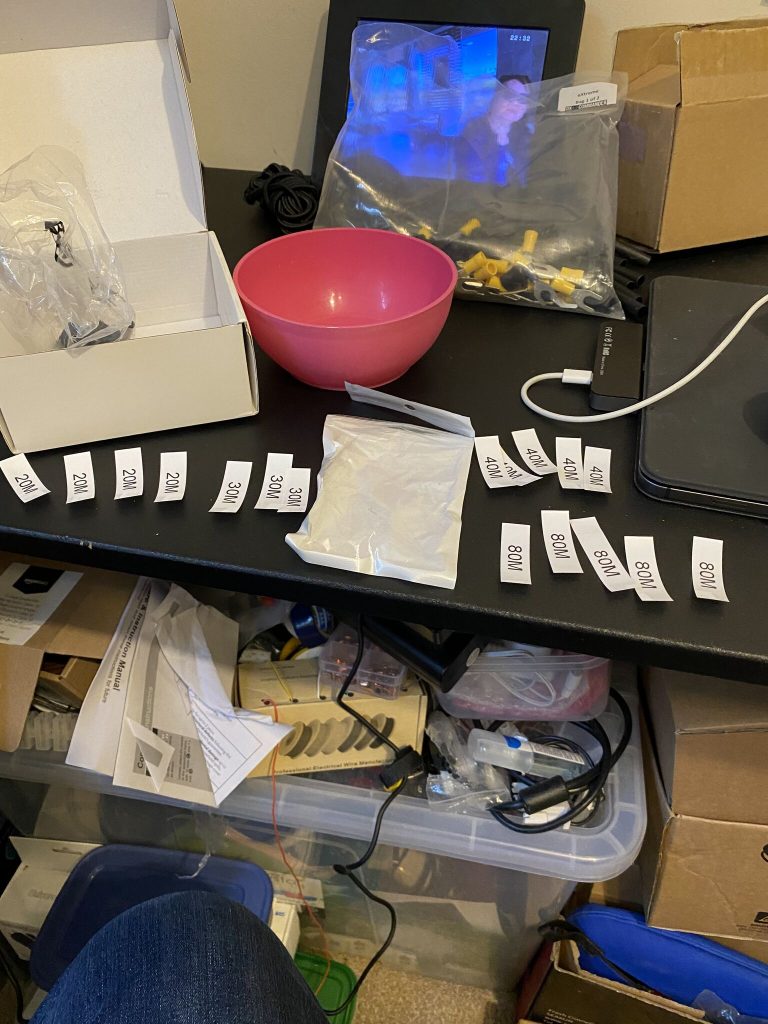
dyno label printer
labels at the ready
applying labels to the correction positions
and the feeder plate
labelling
I’m going to follow Callum’s advice and start with 3 elements, namely, 80, 40 and 20 – as those are the bands i use the most. When i have all the SWR for each band as good as they should be i will add all the elements for more band coverage, but walk before I can run so to speak!
Alignment by using the documentation provided was easy enough and one less job to do outside. I dont like littering and despite my best attempts previousy the label-backs have flown off after sticking on, theres a fair bit of nature (birds,insects,etc) and I dont want to ruin their habitat with sticky label backings (what a hedgehog makes of an 18m mast has yet to b eseen.. I did have a robin visitor earlier this year tho !).
clamps and splicers on
i find these clips fiddly
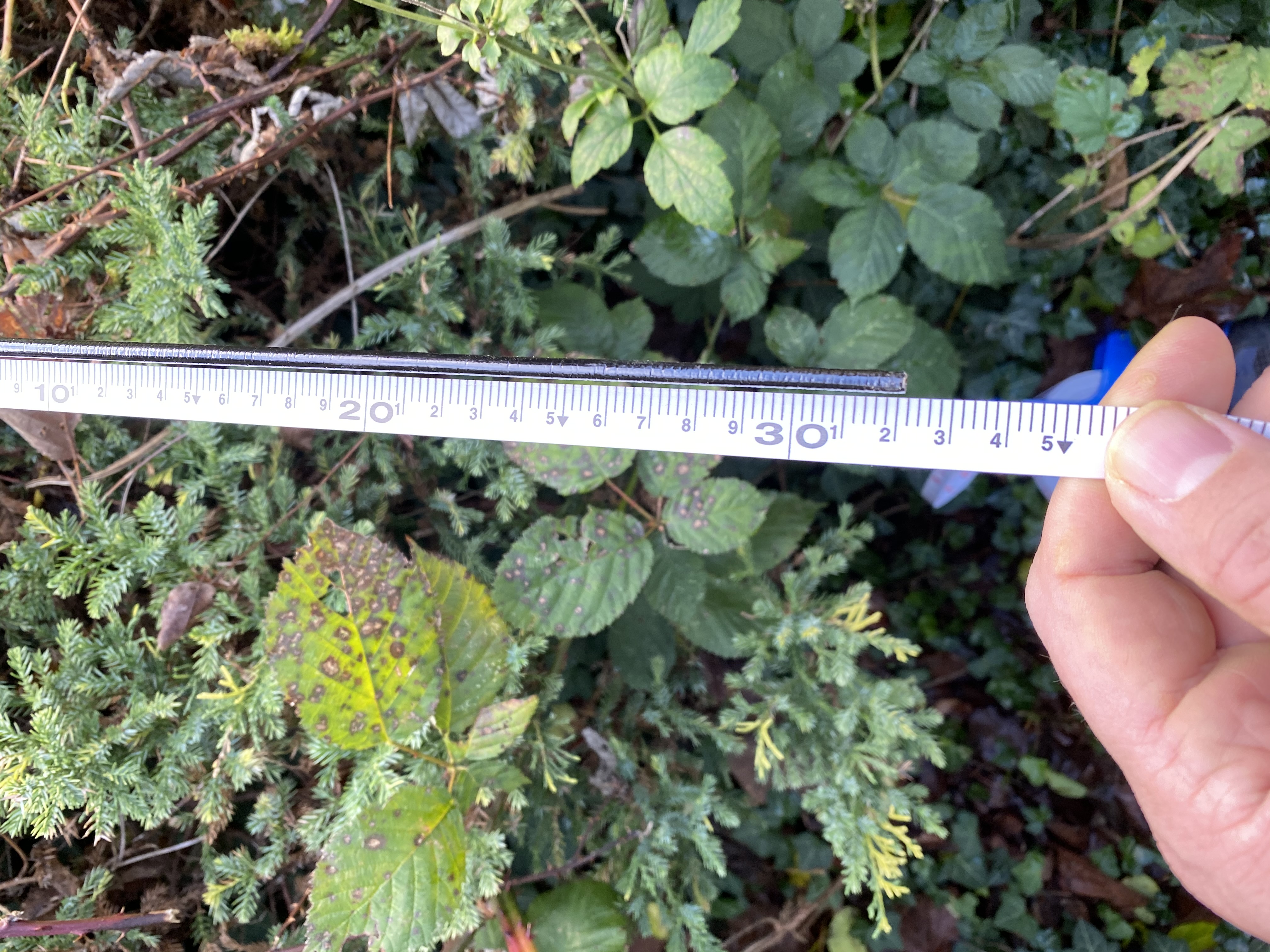
measuring spreader height
classic and nebula
clamps, spreader and classic/nebula side by side
With the spreaders in place i was able to take the measurements of the heights to calculate the length of the guy wires. I’m going to use (as per doc) 1, 2 4 spreader points for guying, but will start with #1 first to ensure my measurements and cutting are accurate. All values are cm
Spreader
Height
Time Self
x=(h*h)+(d*d)
sqrt(x)
total rope
1
310
96100
346100
588.302
2
580
336400
586400
765.767
4
1134
1285956
1535956
1239.336
7780.221
Diameter
500
Guy rope length in sqrt(x)
I will double check these measurements again, so if your planning to do this between now and tomorrow morning – please do check your measurements as mine havent been applied yet!
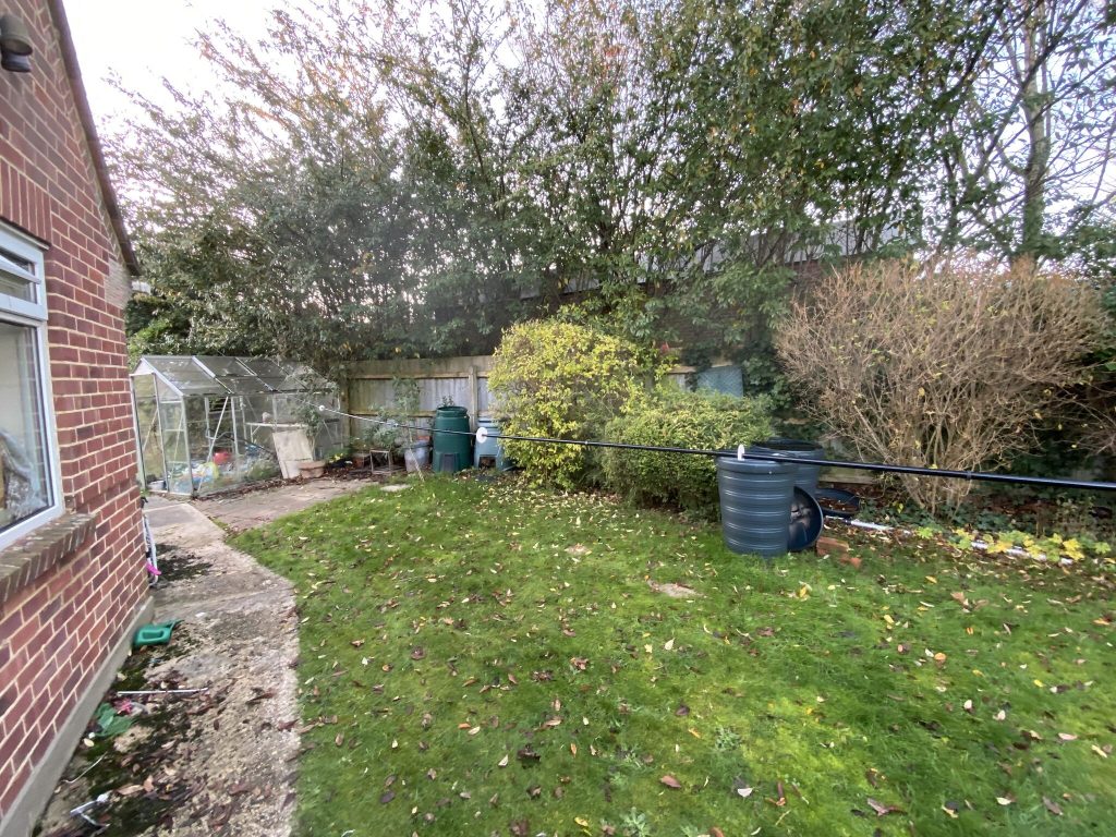
I then set about tidying everything up and removing the existing end-fed wire. This took quite a bit of time and the end fed got caught in the tree – thankfully the tree wasnt damaged and a good ‘yank’ set it free ! Here is my video of the tour of the QTH after removing the end fed and the nebula work-in-progress.
Nebula Day one progres
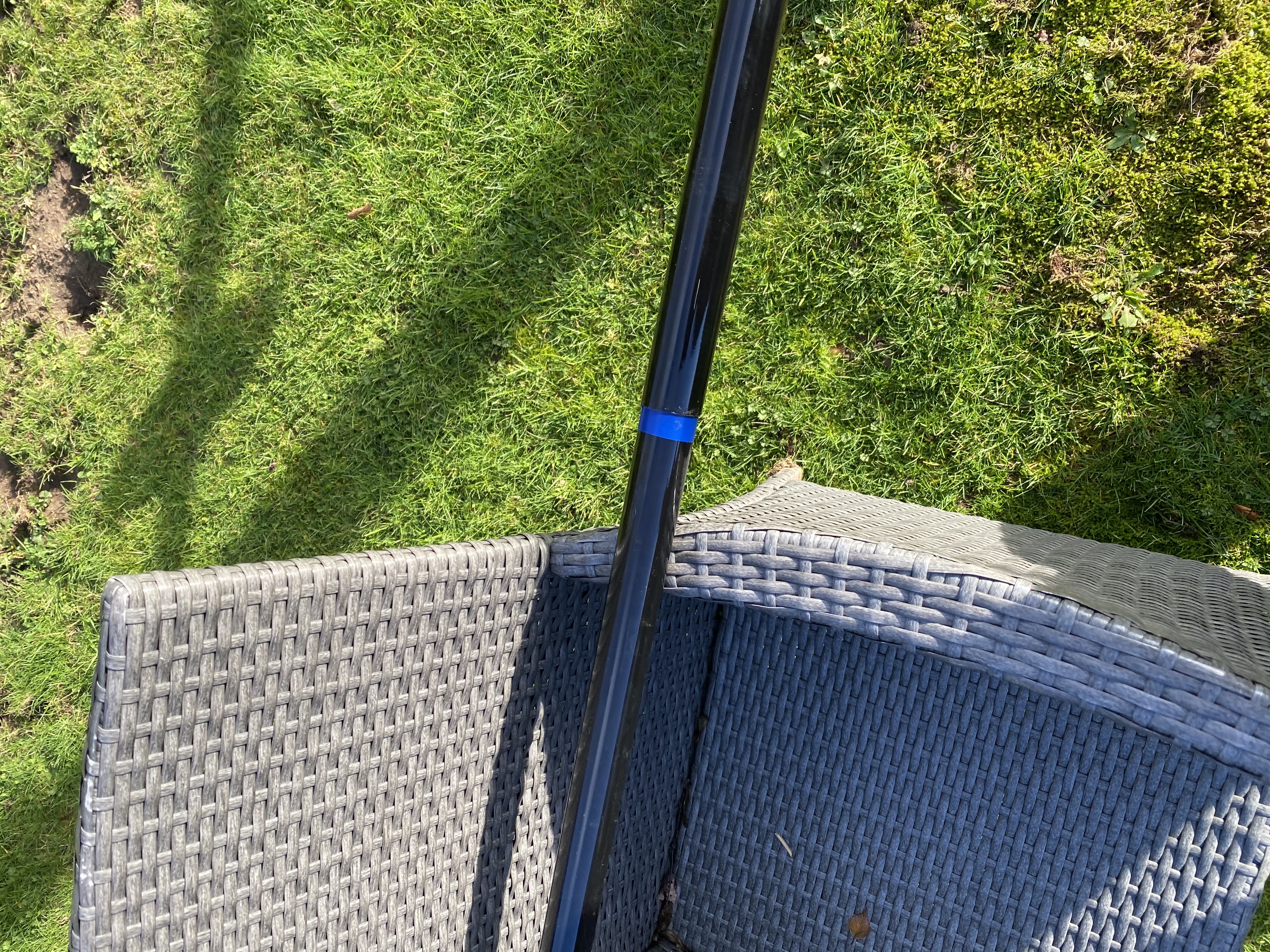
And with that I then moved the nebula to the side garden where it will be erected. It was a real handful to move but i got it around the corner of the house from the front garden to the side eventually and have safely mounted it above ground height.
nebula 1
nebula 2
nebula 3
Tomorrows weather doesnt look as good as todays, so progress may be limited, however I’m pleased with what i have acheived so far, and as ever, am greateful for all the hard work Callum has put into creating what I’m sure will become a legendary antenna.
Stay safe and hope to publish more progress tomorrow !
So having not only being able to listen to G5TM on air today, he published yet another fantastic mobile operating video.
G5TM – Another excellent Mobile session on 15M
I was mulling over what to do today, I always have enough to do, but Tim’s video made the decision for me that I will at least try out my 20M antenna which I had purchased from Thunderpole.
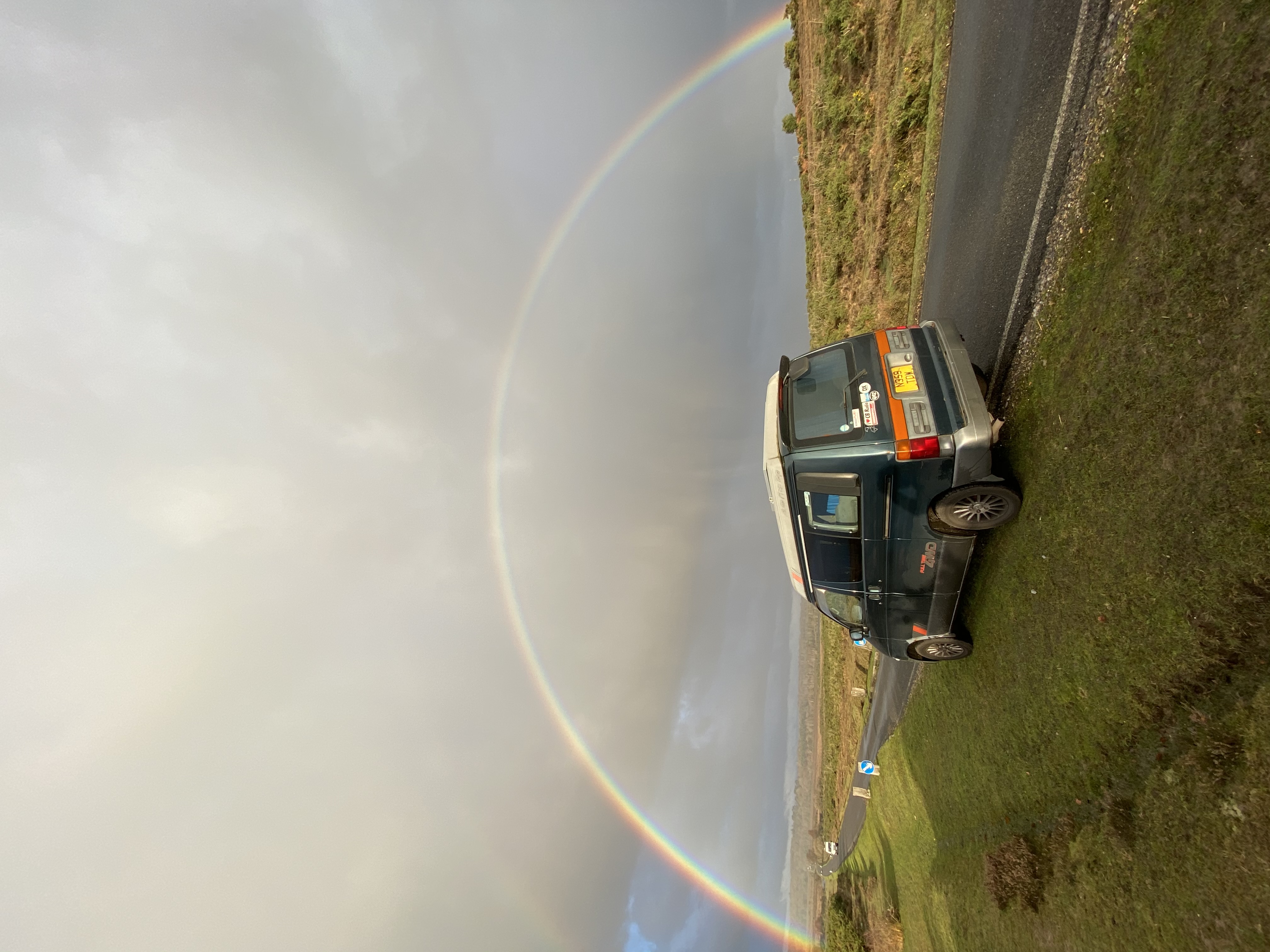
As ever, there was a light drizzle, but i was determined to at least try out the IC-705. My Mazda Bongo already had a fitting for an antenna on it, which hasnt seen much action at all in ove ra year I suspect, but thought I would give it a try.
Mazda Bongo in the New Forest today (no antenna, but a cracking picture with the rainbow!)
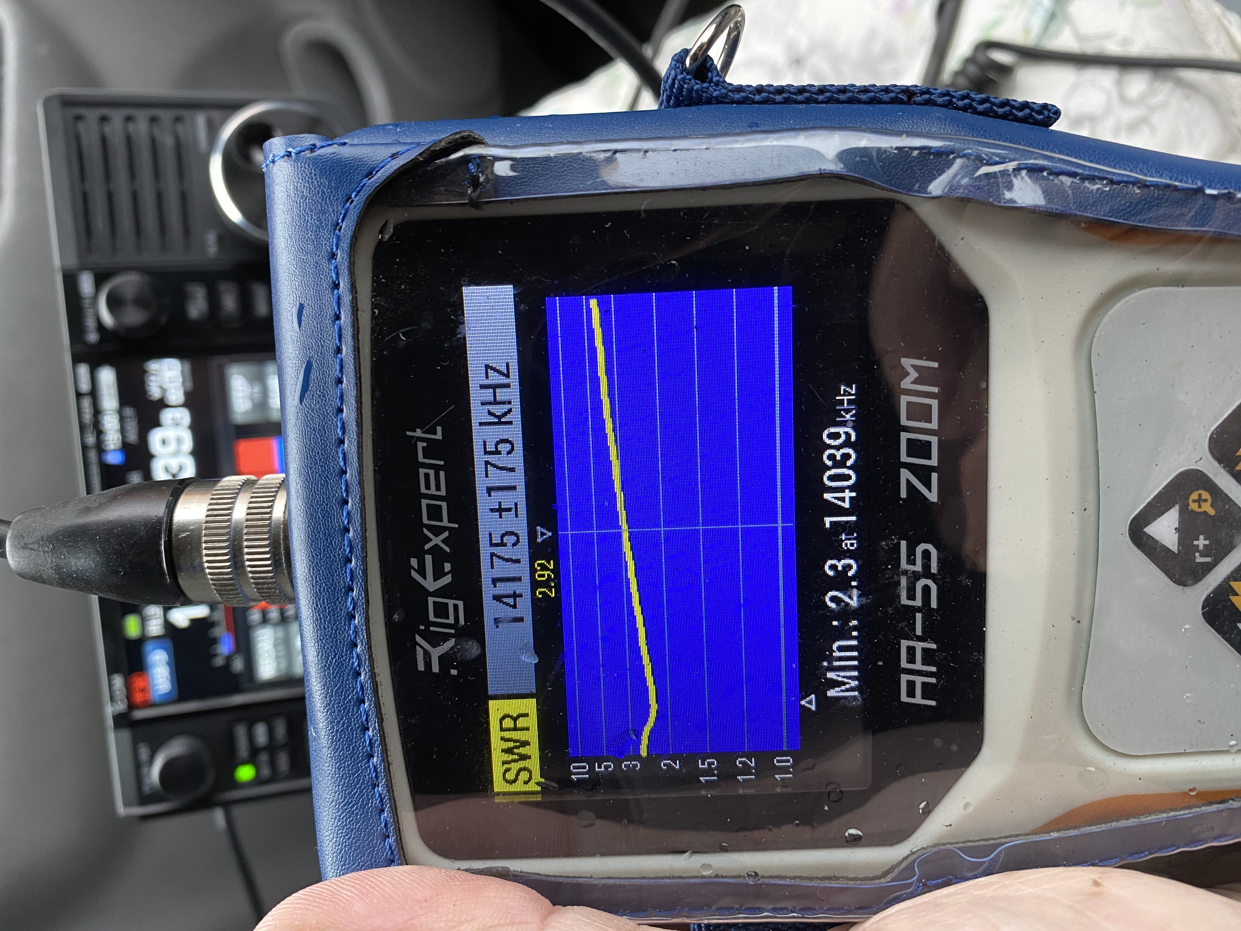
I headed out with the the Rig Ex[ert AA-55 and started to read results off the antenna. First reading was ok
First reading off the 20m vertical on the bongo, not bad, but should be better
I took the anntena down and readjusted the bolts, simple enough, especially compared to putting a great big mast/vertical up and cutting/adding lengths each time.
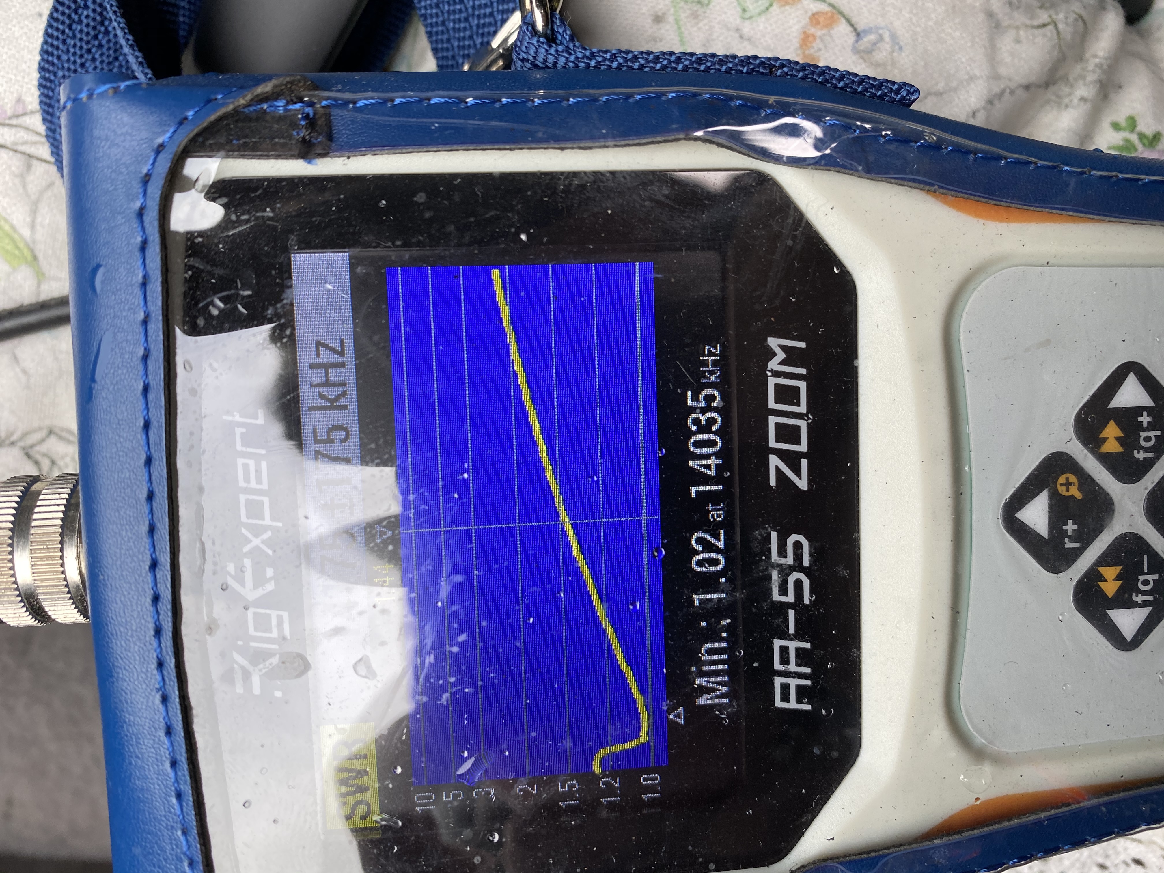
Second attempt – far more reasonable results
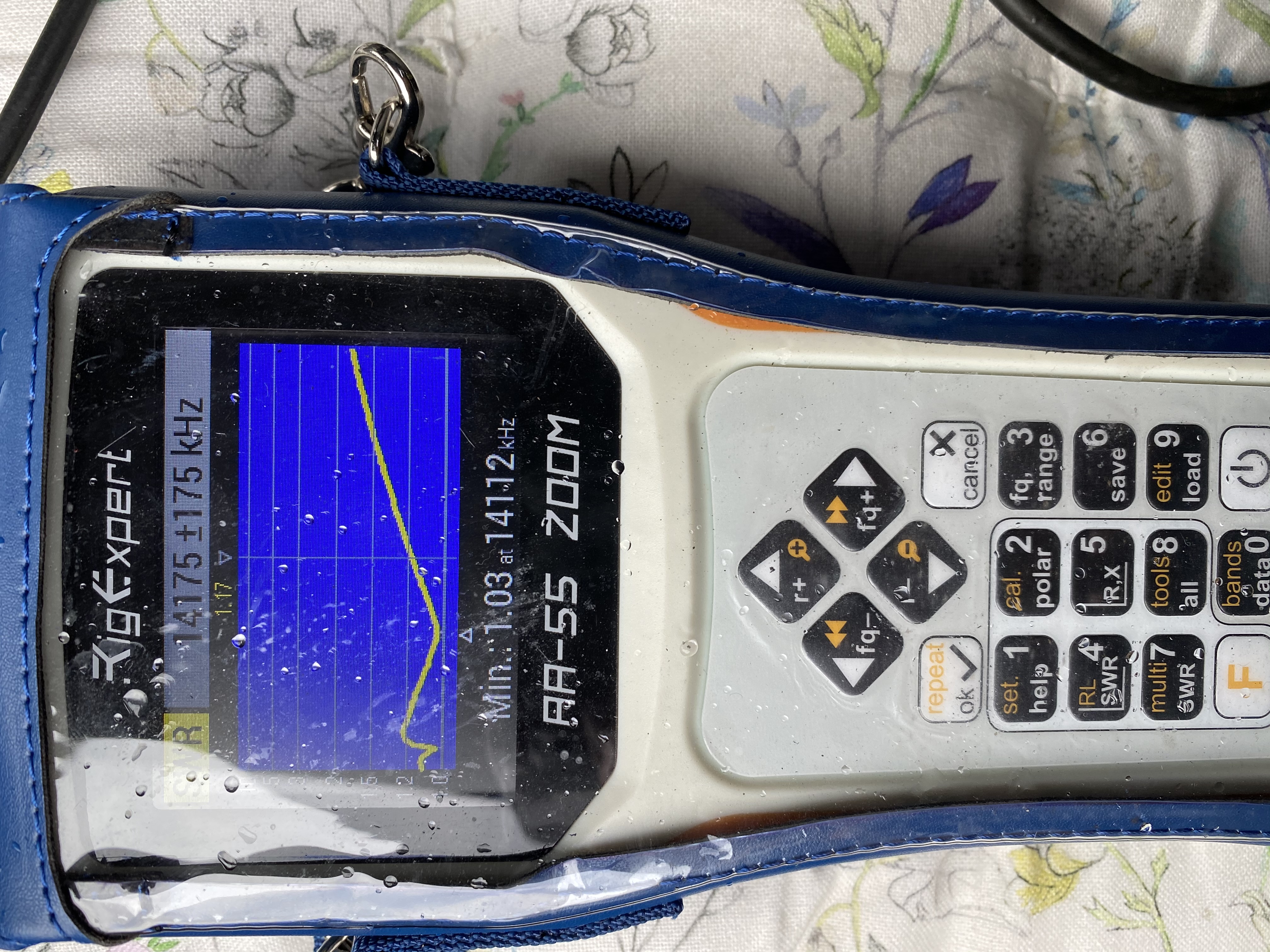
The second adjustments brought very good results with almost less than 1:2 SWR across the band, with a very nice low in the morse area (more motivation to learn morse now !) with the SWR at 1.5 to 2.1 on the telephony side of the band I think this is acceptable, ideally i’d like to get it down further across the whole band but for 30 minutes fiddling, this was good enough to start with.
a bump in CW, but <1:2 on the upper half ot the 20m band
I continued my fettling and got the SWR down to 1.03 and less than 1:2 on the SSB telephony range. For a £19.99 antenna, i think this is a satisifactory result. I then went about attaching the IC-705 !
IC-705 in the bongo attached to a 20m whip
So i was very happy with the reception across the 20m band with the whip antenna, apologies for the quality of the video with putting my phone down,etc – i’m not even an ‘amateur’ when it comes to making videos like this, but I will get better 🙂
I tried a test transmit but the SWR was way off the readings the rig-expert had given me, which was slightly disappointing, but if everything went perfectly the first time of trying, it would make it the interesting hobby that it is.
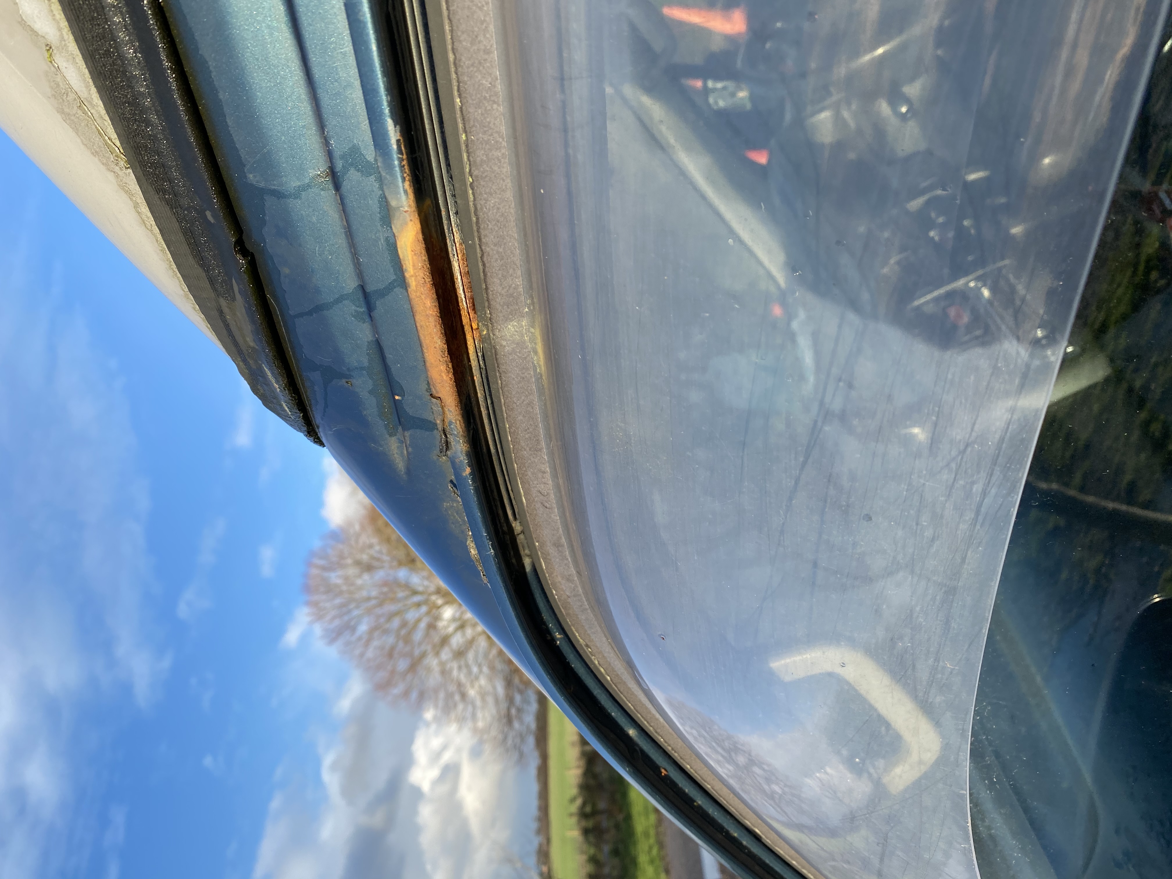
As i said, the mount has been on the bongo for quite some time, and the metal around it has got quite corroded.
Removing the antenna mount from the Bongo revealed more rust
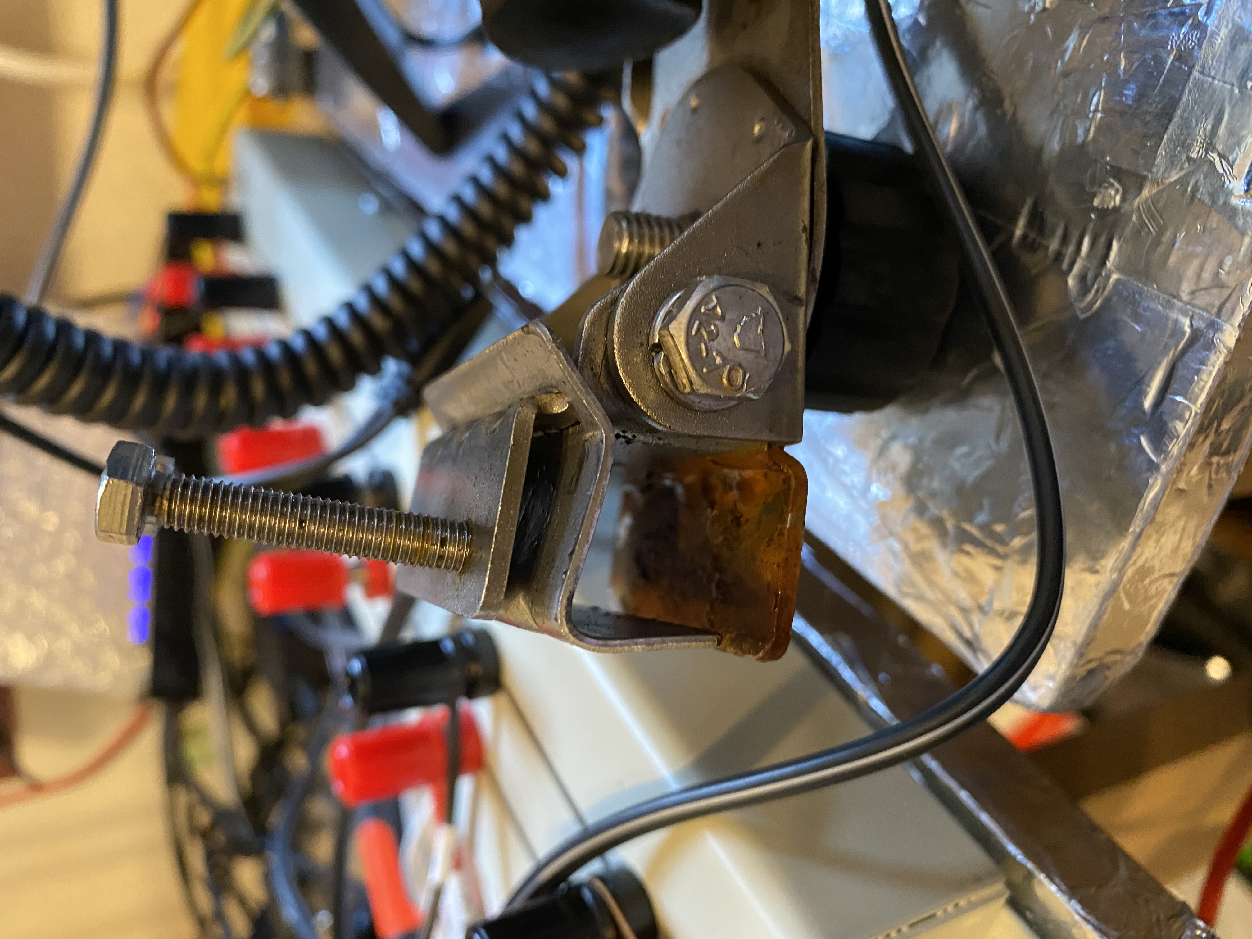
So i have brought in the antenna mount and intend to rub-back the rust and treat it before returning the mount to see if the SWR improves.
Rust on the interior of the clamp
I still am very happy that the intial experience was generally positive and am very much looking forward to operating mobile.
I’ve ordered an ATU kit from america, but that will take some time to come (Jan 2021), but am looking forward to building and trying it out!
Fantastic news is that my shipping label notification for the DX Commander Nebula arrived in my inbox. I am really looking forward to this antenna – hopefully it will be with me for this weekend.
I have measured a 5 meter guying radius ready for the whopping 18 meter tall antenna.
https://youtu.be/RZHtHMOAPCQ
18 meter tall !
I reckon the build will take some time, everything is quite scaled up. So now I’m waiting for that big package to come.
Exciting – yes – alot of work to do, VERY MUCH SO !
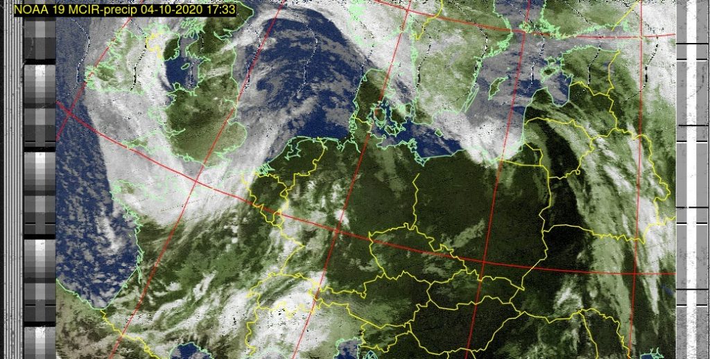
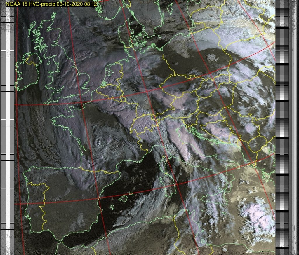
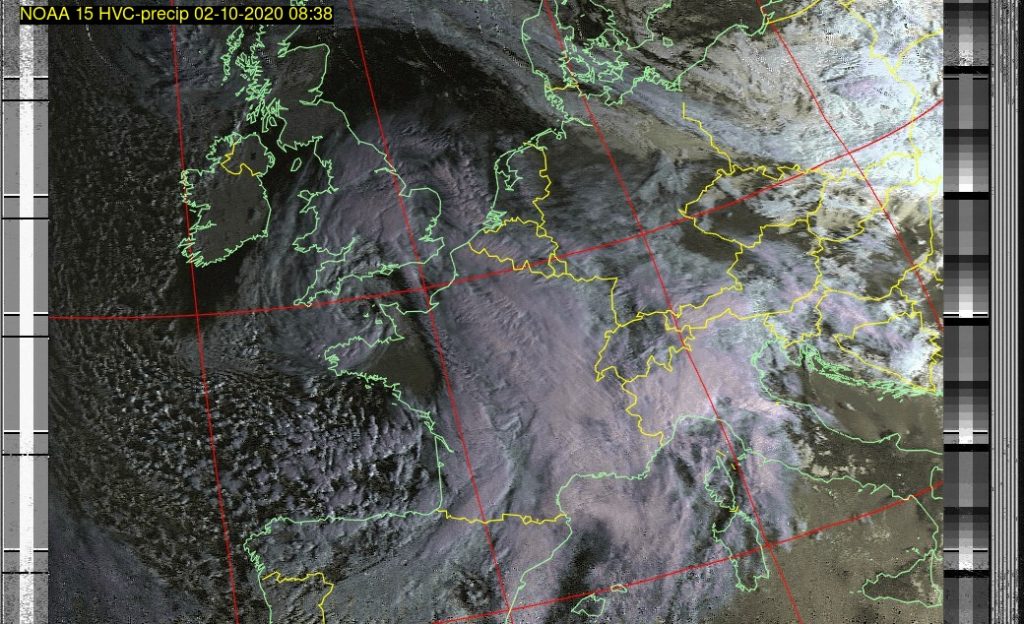
I can report that all the rigging and daily inspections insured that the end-fed antenna stayed up well despite storm alex lashing down wind and rain of epic proportion !
storm alex
storm alex
storm alex
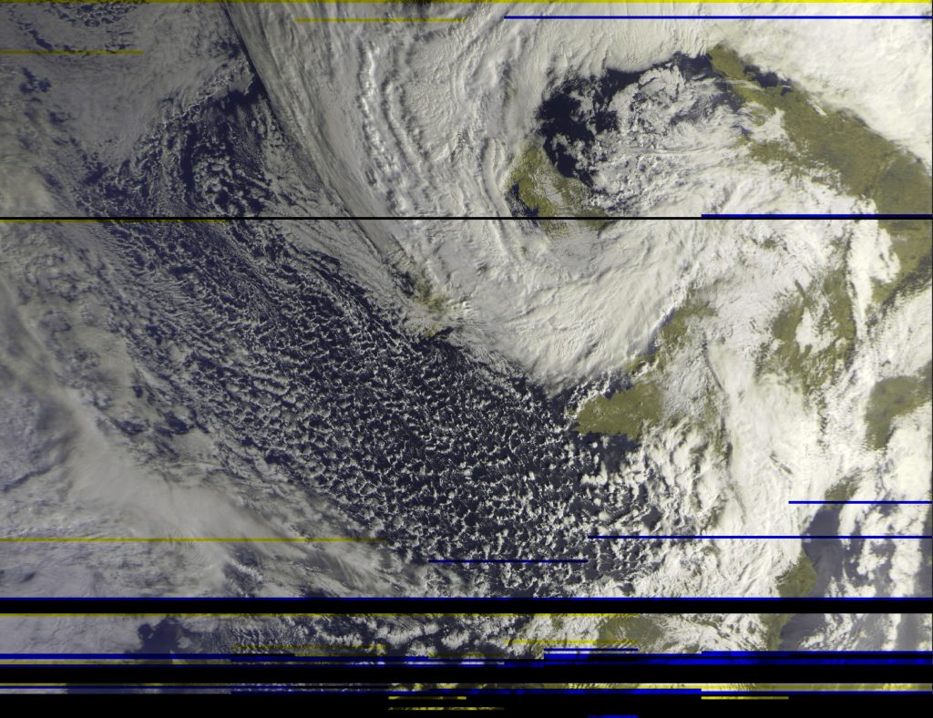
storm alex – METEOR capture
Storm Alex hits the qth in southwest england
Whilst I have been enjoy several QSO’s on other digital modes (SSTV, BSPK) other than FT8, id thought I do an update on the next steps for the End-Fed antenna.
Whilst my signals are not bad, there is a noise floor present. Whilst I have largely removed alot of sources of QRM from ‘the shack’ (see earlier posts on QRM) my end-fed antenna seems particuarly good at picking up ‘noise’. Maybe its good to state what I think noise is as well.
When I tune the radio, I should be able to, ideally, hear all stations on that frequency (and mode). What noise brings is either man-made or remote interference to a weak signal. For noise that is ‘local’ the weak signals hide in a ‘noise’ band, this can be upto S9 for thinks like washing machines/VDSL/construction equipment.
With the ‘local’ noise its possible to use the an external antenna (lets call that a receive antenna) and transmit on the existing antenna, then between the two ‘phase’ the noise until it is no longer present.
I am going to use the MFJ-1028 noise canceller as I was using this already with my Kenwood and DX-Commander multi-band vertical, but as both a send and receive antenna making using of the ‘T/R Delay’ – The Icom 7300 doesnt come with its own ‘receive only’ port unlike its ‘bigger brothers’ in the Icom range, but is easily adapater to have one via the a plug-in kit from Inrad.
The installation looks simple enough as shown in the video below. I face the challenge that I am also using an external ATU (MFJ-993B) so getting both ports in will mean doing the install slightly differenty.
INRAD RX7300 mod
I have a number of antennas i could use as a receive only, but a recommended ‘noise gather’ is the ‘mini-whip’. I picked mine up off ebay and it arrived in a bout a week.
I have yet to install the miniwhip, but have all the necessary parts, including a rather impressive 4th ground pole ! I will be following the guidance from the following video
I will first try using the mini-whipa and end-fed combo and feedback on results !
Hopefully there will be less bad weather in the coming week allowing more ‘build’ work outside, for now i’m glad my masts have stayed up and we are all staying safe at home !
Having originally booked the Intermediate course and exam back in March events stopped that happening.
Thankfully the RSGB started with the Foundation Level exam in starting on-line exams and rumours of the Intermediate being made available on-line soon started. I had been building my kit for assesement since earlier in the year, and not sure what would happen about the practical assesment carried on with it, albeit at a much slower pace !
In July it was announced that the exams for Intermediate would be on-line so I immediately booked mine. I wanted to give myself enough time to kick-start my learning and give myself the best chance of pasting, but also fit in with everything else I have going on. Post September alot of my time outside of work will be taken up with my MSc and I had already booked a holiday for the bank holiday at the end of August, so went for August 23, first thing in the morning !
All the participants of the exam were given an invite earlier in the week and hooked up. This was a great idea and we was given a nice introduction to our group. Vitally I learned i would need *two* webcams, one on my PC I was using and another to see me from behind. So i set that up via my ipad. I would say if you dont have 2 webcams, use your PC for your main camera and use your phone – you will need WebEx on your phone, but belive that is possible.
In the two weeks upto the exam I made myself a schedule and broke down the notes/exams questions into days. I found this really helped me understand where I need to focus my learning. I had no problem at all on anything related to licencing and safety, most of the challenges come from the maths and equations on theory.
Invaluable advice !
Although the video came out close to my exam and the revision was well underway, the video from Tim G5TM really helped ! I followed his techqnique and it made me much more at ease during the exam. I took my time and went thru the ones i knew for sure and left the ones i didnt until the end, and at worse could take an educated guess – but i was in control (or it seemed!)
In the week leading upto the exam i continsualy tested myself on both the RSGB provided Test Papers and the questions in ‘Exam Secrets’. I cant recall the questions word-for-word but for sure there were many that were very close to what were present, and probably doing the test exams in ‘rote’ method got me over the line to get a pass mark 🙂
The only negative side to the on-line experience was other people making a noise during an exam, as they finished or whilst they worked, there was a level of noise I wouldnt expect during an exam situation. For this i just removed my headphones and concentrated on my exam but listening for anythign that the invigulator might say (rather than just random noises).
I was told immediately of my score and I had passed, so am now just waiting notification from Ofcom so i can apply for my Intermediate licence ! I can wait to setup a working beacon and use 50W on HF, i think it will make a difference on the telephony contacts for sure.
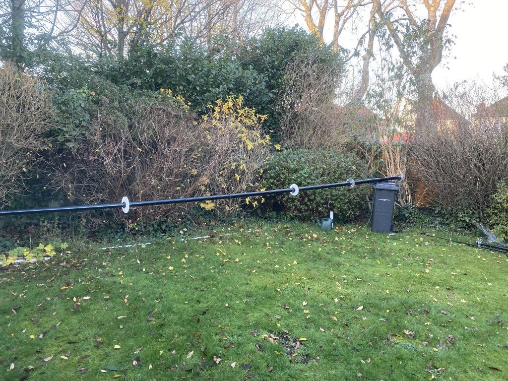
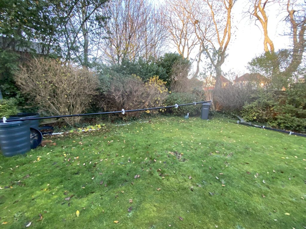
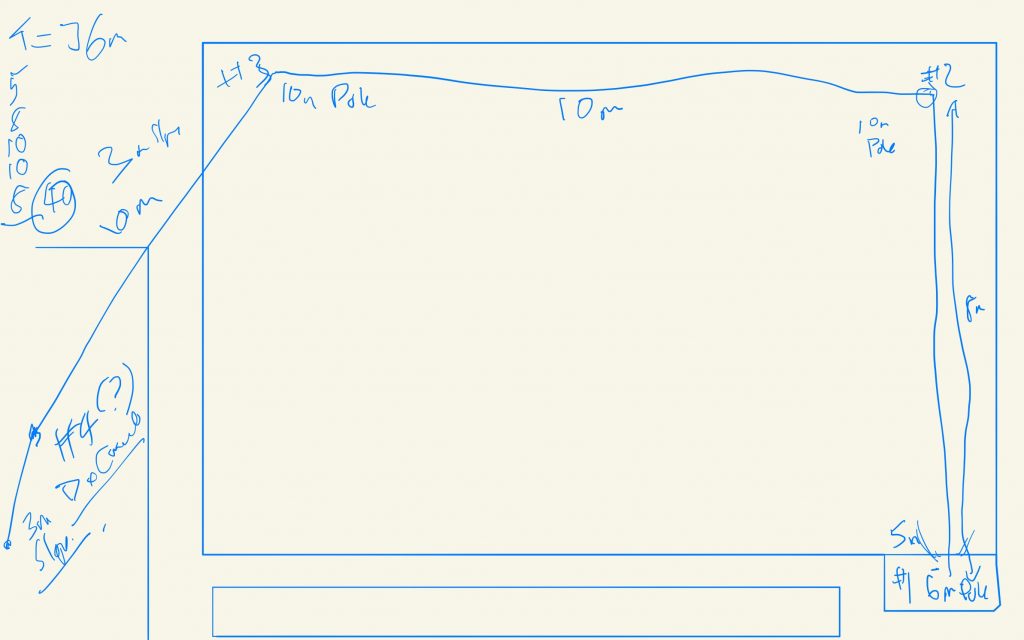
So in the QTH down in IO90 the met office issued their warning of bad weather. I brought my antennas down as a precaution of lightening strike. Following a couple of messages on the DX-Commander Discord channel the UK Antennas multiband end-fed was mentioned as a comparison. As such I’ve not had the time or opptunity to get it in place, and with the wire at 39 meters long would require some prep on how to get it in place !
planning the long wire across the garden
The advantage of the DX Commanderj is that all the bands are vertical each, even 80m can be done lengthening the wire. With the End-fed finding how to route 36m of wire into the space I have was a challenge.
I have made a draft and took some measurements, and in combination with some sorta beam poless and mast, think I have a working configuration !
Will post as soon as the good weather has passed, really excited to try out a new antenna
Well its been busy and for the last few weekends very mixed weather here in the UK with masts going up and down due to the winds and more recently forecasts for thunderstorms ! having just passed a mini heat wave here in the uk, it seems the weather, albeit the wind is still blow a bit, has calmed down somewhat !
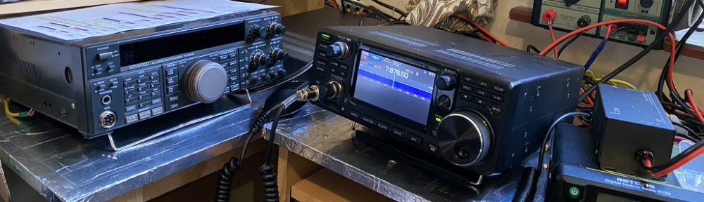
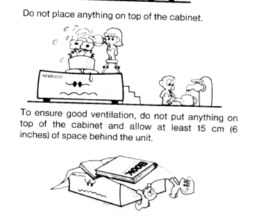
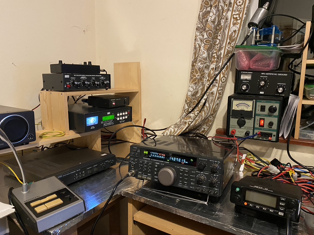
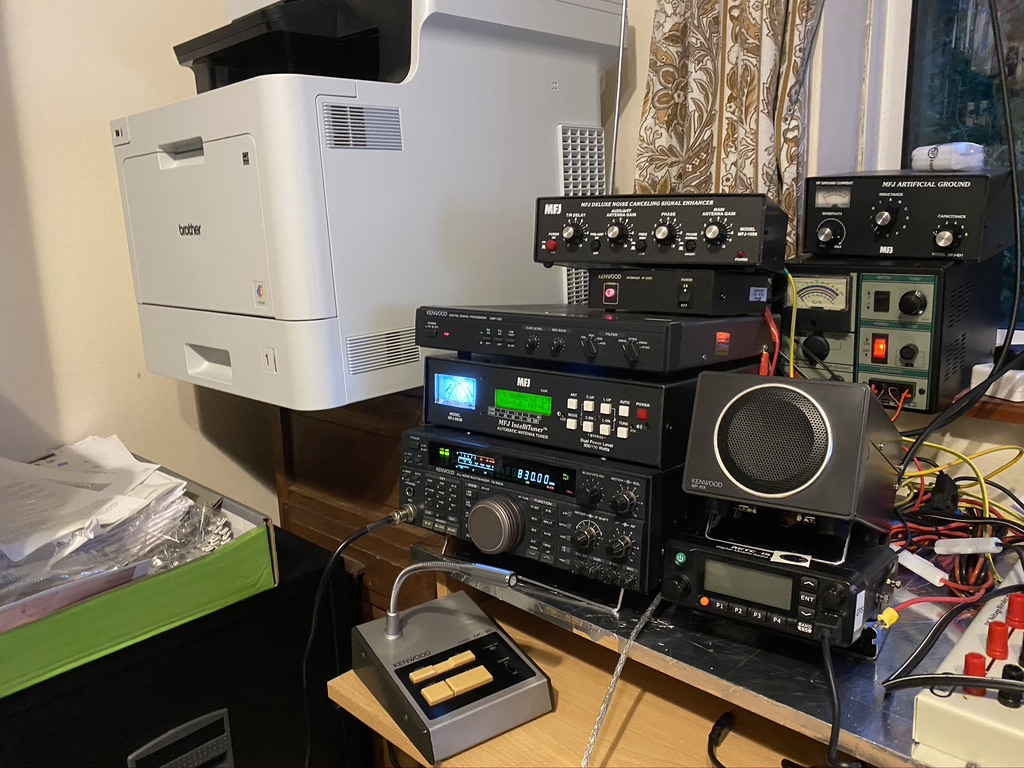
With that I have been tidying up in the shack some more whilst I coudlnt transmit. One thing I was not happy about was the amount of vertical stacking on the TS690s.
The TS690s – keep it ventilated !
I had a room re-jig and moved all the book-cases to allow an additonal desk to put the associated radio equipment on. This got the same earthing/bonding treatment i had done for the orginal table, which is giving a good common ground amongst the equipment.
A well-breathable TS-690S and DSP100
I’m much happier that with moving the printer and giving room for the equipment it gives a better layout to operate it. I can quite comfortably operate the transceiver from my computer, or if i want to get close and use it direct, have plenty of room.
I have been doing antenna fettling and this weekend and general mast tidying, but thats for another post when i figure out how to show some other developments as well 🙂
The main speaker on the Kenwood TS690-S is not a bad one. I’ve been using it now for around 5 months, and although no expert, it has been good in terms of being able to listen to what ever made it thru the antenna and to the audio stages of the transceiver.
However, with the addition of the Auto-tuner and DSP, there is quite a bit which ‘blocks’ the speaker. Whilst not muffled, its ironic that I have such a good DSP and not a good external speaker. I do have a very good mixing desk (Behringer X2222) which I use on ocassion to process and amplify the audio from the transceiver, but ordinarily I keep the radio audio seperate from the synths/drums/guitars. Another issue would be managing the sizeable ground loop between mixer and transceiver as the earth/bus bonding isnt the whole way around the ‘shack’ yet.
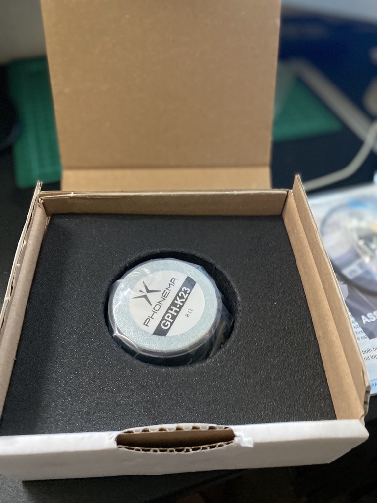
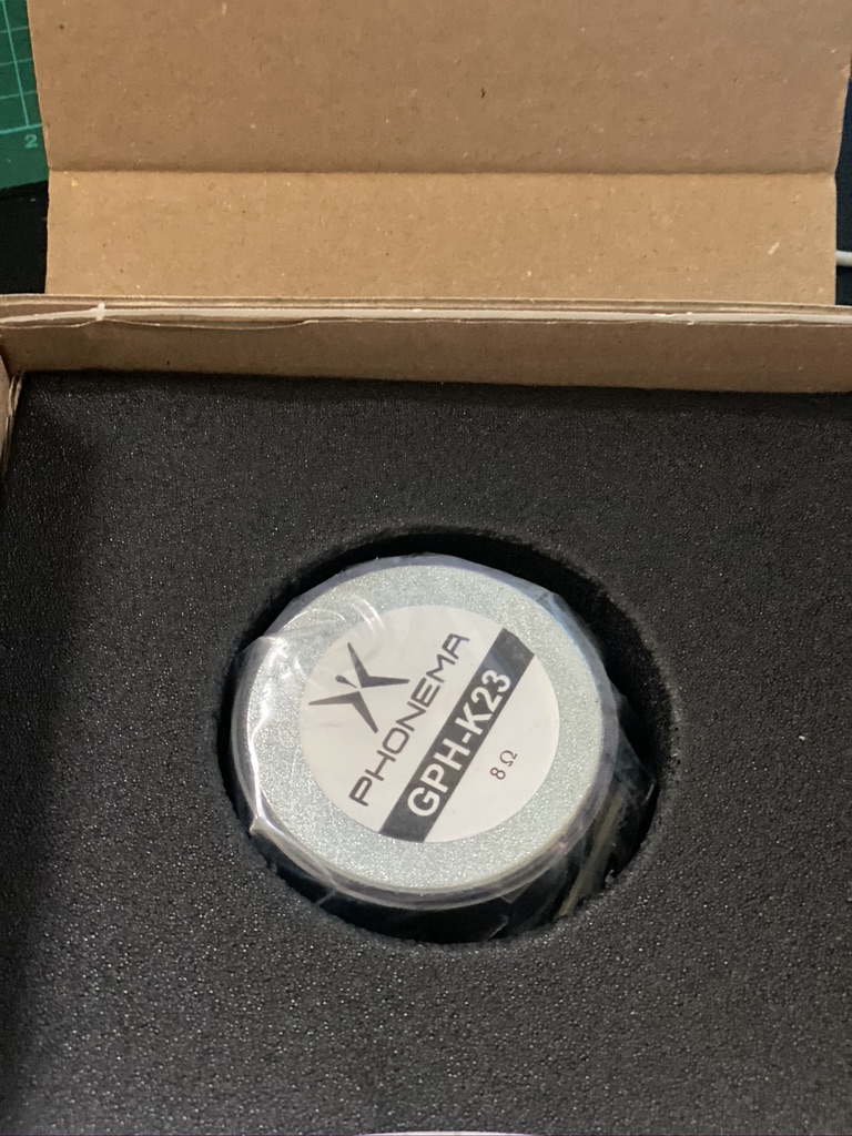
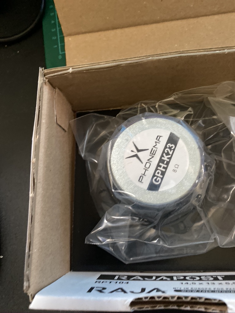
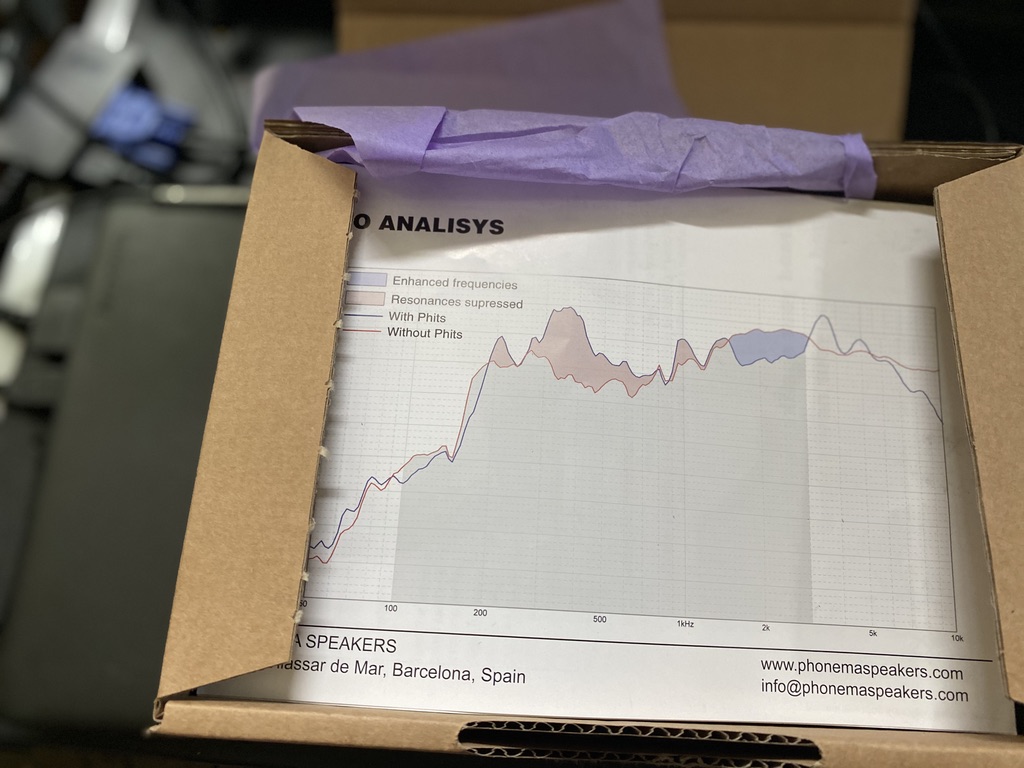
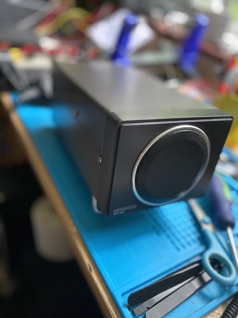
This lead me to search for a speaker for the TS-690s. Whilst not an ‘audiophile’ I do understand a little about speakers, housing and acoustics of them. I was very lucky to find a really great condition Kenwood SP-23 from ebay. The item itself is in incredbly good condition. I cant tell if its one month or 10 years old. It looks gorgeous. When findng the SP-23 I also searched for upgrades to it, this is without hearing it, but I’ve come to trust the reputable amateur sites on the internet, for example eHam reviews of the SP-23 talk about the quality *compared to other speakers* – I guess when you buy a speaker you want it to be the best buck for money. The most often given upgrade was to the GPH-K23X speaker and applying Phonema K23A PHITS acoustic coupling. I ordered both immediately and was amazed that these arrived from the USA in just a few days – amazing work from FedEx.
Having had the speaker for several days un-modded I was quite happy with the audio quailty. That said I still dont do enough telephony work to really say how good it was, and other than the internal speaker have no real reference on what ‘good’ is in terms of HF transceiver speakers.
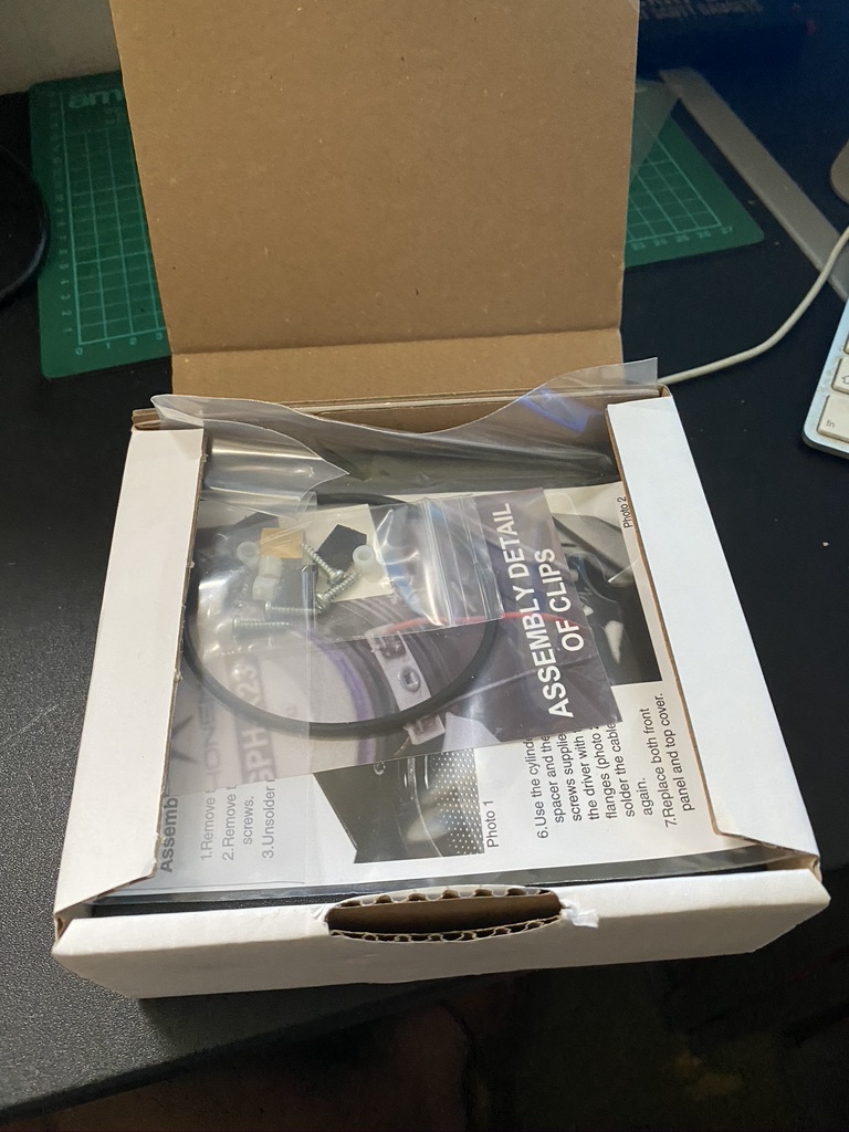
As the kit arrived so quick, i jumped over a couple of other projects to immediatly upgrade the speaker and apply the acoustic foam.
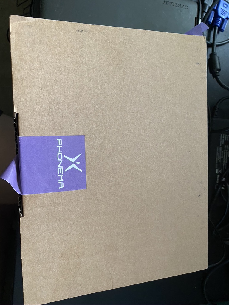
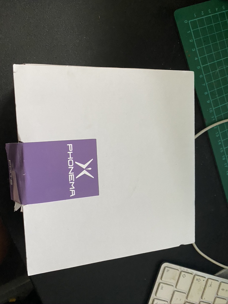
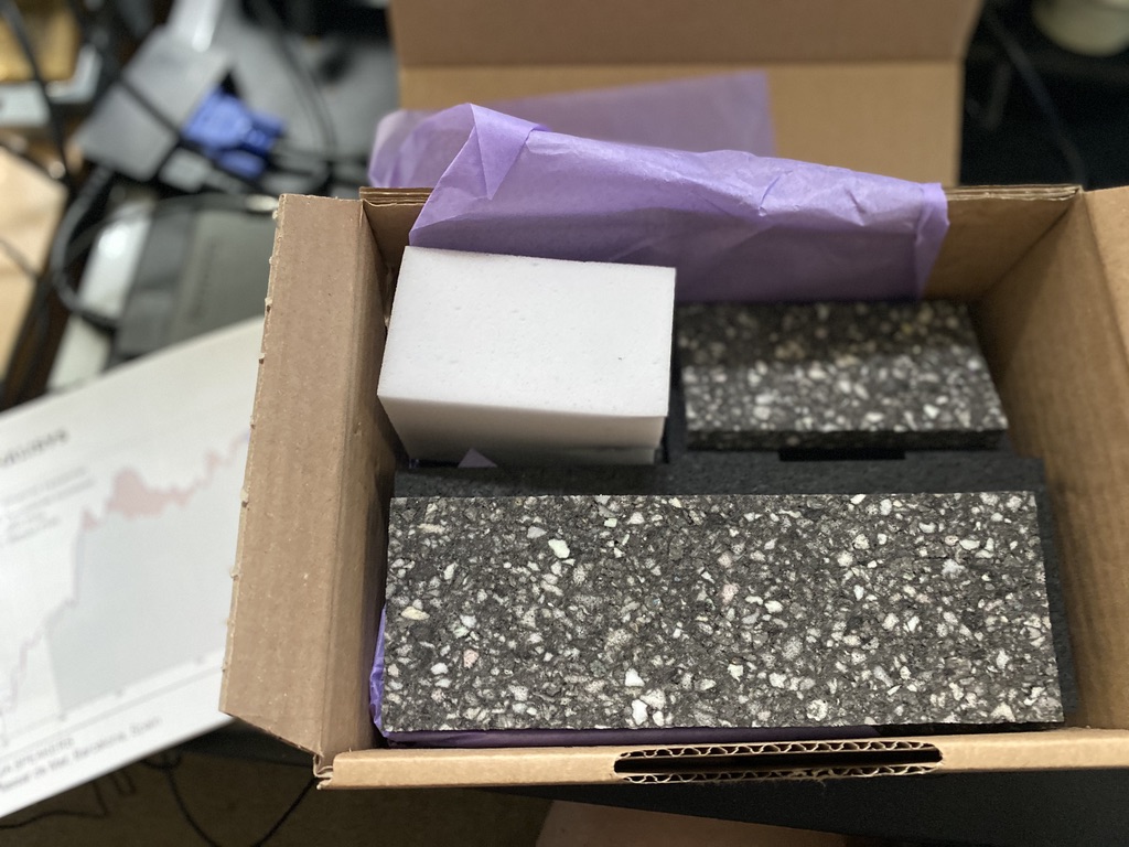
Very well packaged a deent box for the foam
The speaker box is very good dimensions
A manual and parts for mounting the speaker, or not
Briliant foam
A good bag as well to keep it clean/dust free from factory
further packing under the speaker
parts packed nicely in a seperate bak
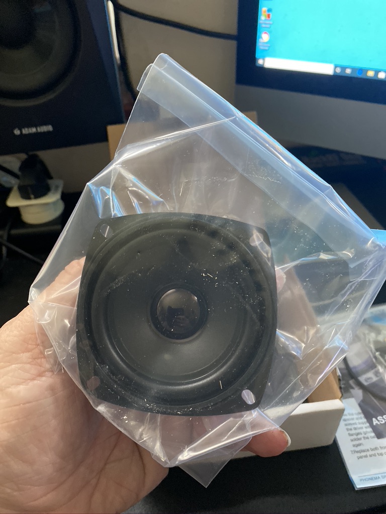
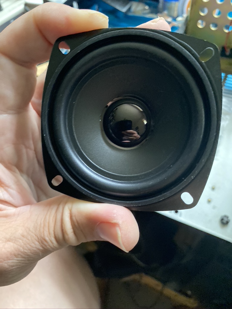
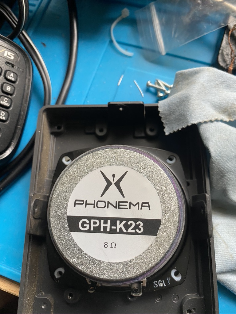
the speaker looks very good quality
the magnet and voice coil look substantial
the foam is very dense
very well packages
even a spacer to keep it tidy – ensuring no bent edges
a useful datasheet
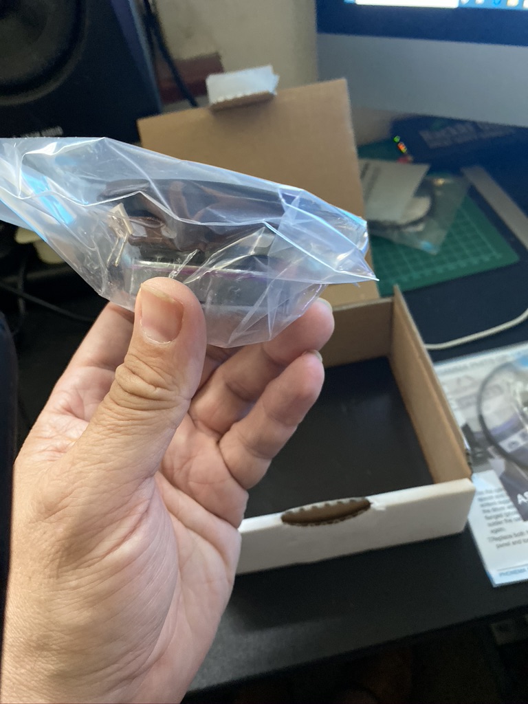
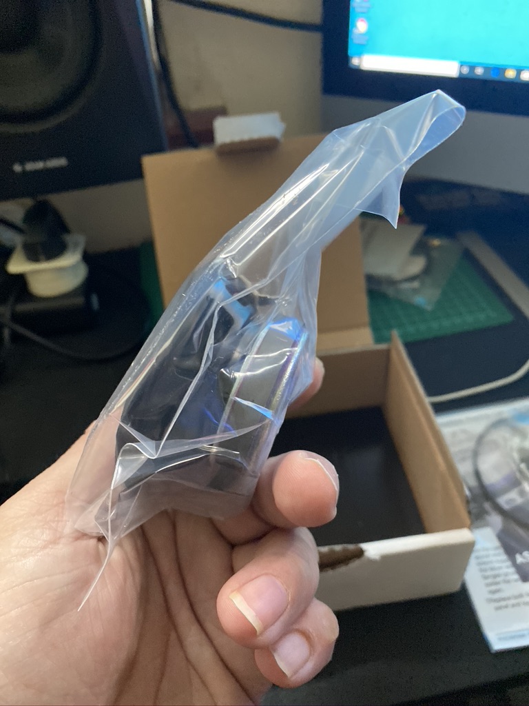
Unpacking the speaker upgrade parts
I was really impressed with how well the speaker and foam had been packaged, its quality throughout and is a good sign that this is a quality purchase.
one last look at the unfettered SP-23
a clever way to mount the speaker imho
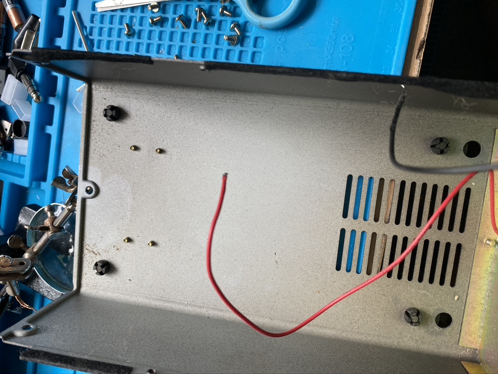
removed speaker
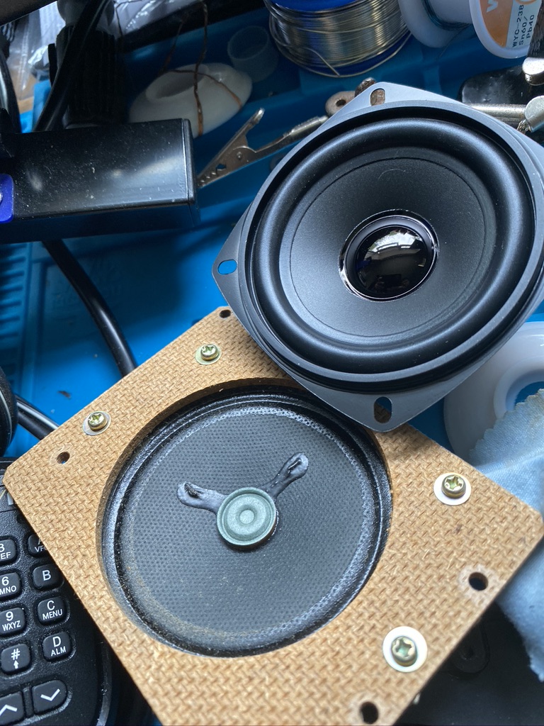
woah its big
side by side comparison
so wheres it gonna sit ?
how does that fix in there ?
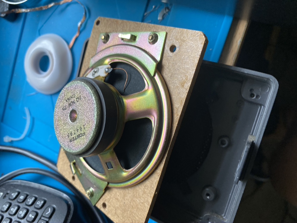
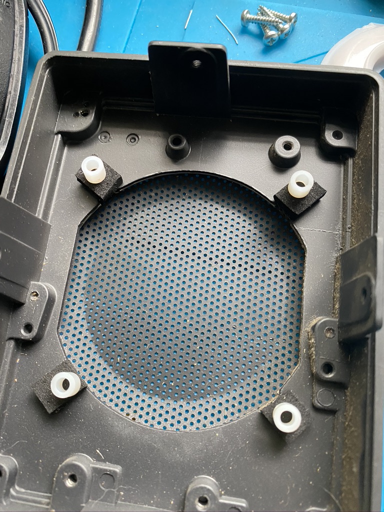
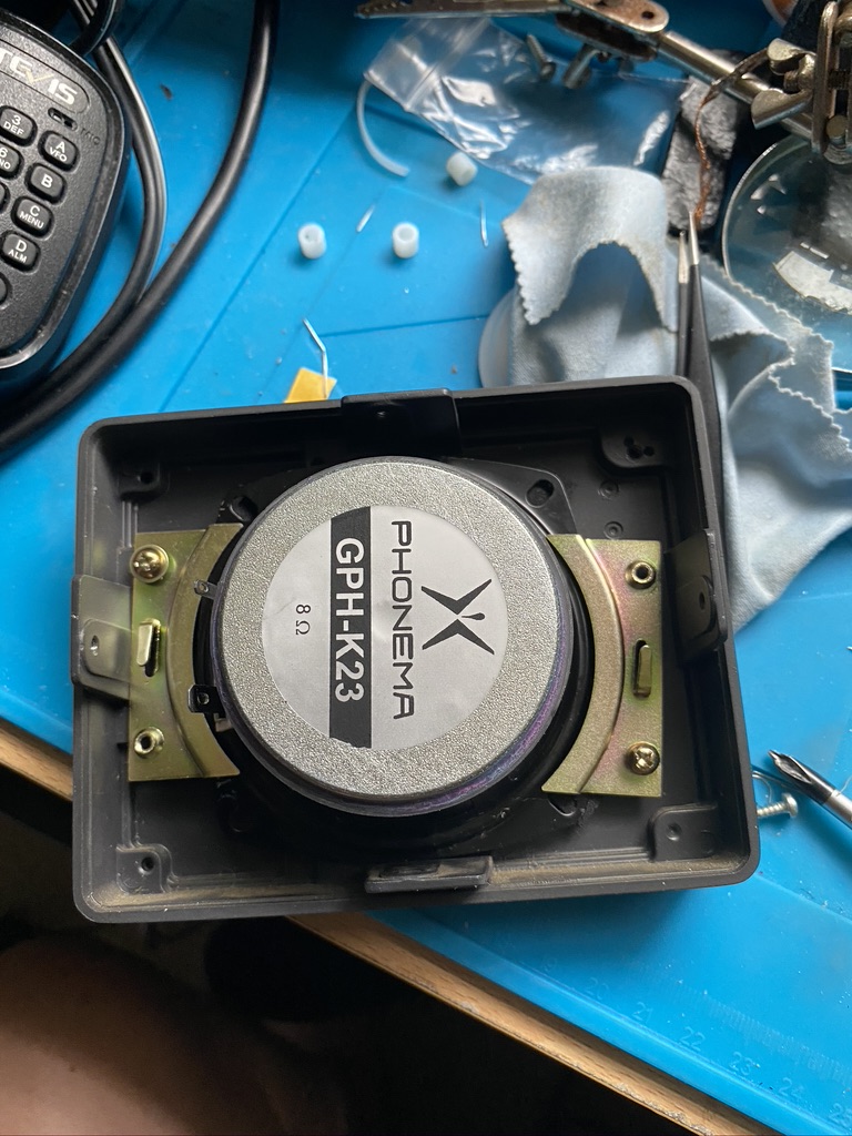
Removal of original speaker and first attempt to instal GPH-K23
I am always slightly relectant to make changes to orginal equipment, but when I do I make sure i can recover it back. In this case i carefully de-soldered the orginal speaker. I did have to cut a little of the positive wire as it has been wound so well, but it was a minor inconvieane.
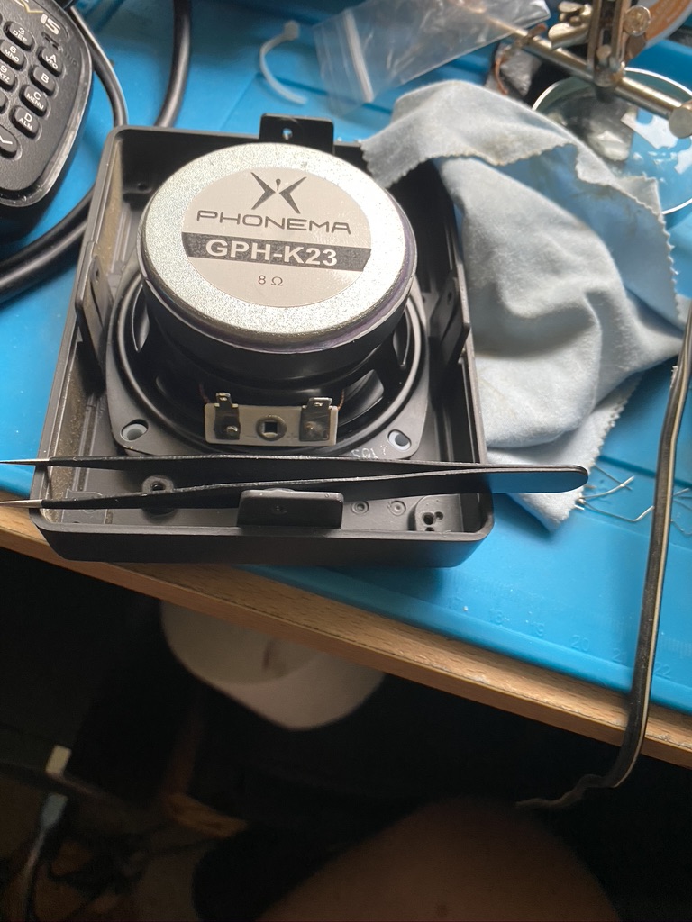
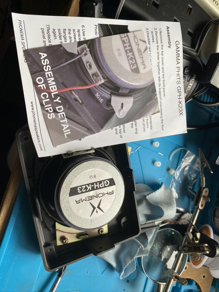
I was then able to start trying to work out how to install the new GPH-K23. Reading the instructions it discusses a bracket and furthermore has pictures of ‘clamps’ which are not visible in either the kit or in the existing speaker. I was slightly confused how this could happen, give this speaker is designed for the SP23. In the website for the GPH-K23 is describes a ‘plastic’ front version of the SP23. Mine is very metallic. With that i was somewhat perplexed on how to mount the speaker, especially as I had now de-soldered the orginal speaker just moments ago.
how does that fix in there ?
trying to use tweezers wont help
this picture looks nothing like my speaker cabinet
improvise..
adapt
overcome
succsses ?
speaker cone very central positioned
fitting the GPH-K23 to a metal-front SP23
I was undettered by the fact that the instructions and mounting didnt match. There must be a way to do this. I had kept the old parts safely, ready to be placed in the SP-23 box so that they are there for future records and changes if required. I examined the brackets which held in the orginal speaker. The backing card was too small (diameter of hole) and too thick (widness of backing card) to mount the new speaker on.
Looking at the parts I had and the design of the case, there was a possibility to use the ‘brass’ clamps from the speaker back to hold the new speaker in place. I tried out the existing screws to check a good fit, and sure enough i was able to use the brass/copper mounting plates to hold the speaker in place !
Looking from the front the speaker looks very centrally located.
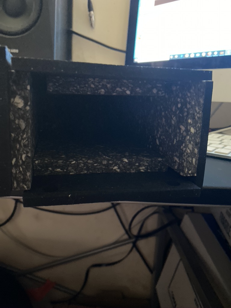
Foam added
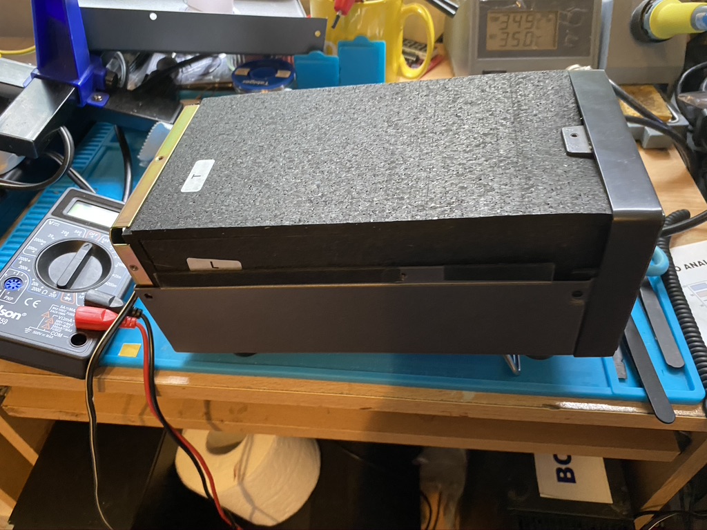
and back in the stack!
the isolation foam makes the speaker a good weight
The foam fitted really well in the speaker, i was very impressed with the cutting and density of the foam. Getting the case back on required some real effort to it fitted, but on it went and back in the stack it went !
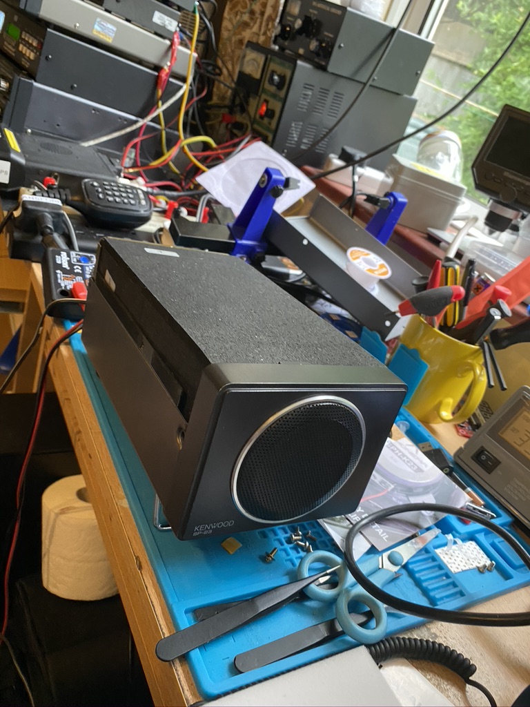
Now, i think its very subjective on how good something sounds, so here it is in action.
Sp23 listening to broadcast radio and the 40 meter band
I for one was very impressed and felt the additonal parts did bring something to the speakers audio clarity. I would recommend that anyone that does have the SP-23 to get the coner and baffilng. I had to choose between one or the other, start with the baffling !
*** THIS POST CONTAINS INFORMATION ON BUILDING A MAINS RF FILTER – IT IS NOT AN INSTRUCTION. IF YOU BUILD THIS IT IS AT YOUR OWN RISK ***
So I never knew just how much can be done to reduce QRM and where it comes from ! Having bought some ferrite rings and having mixed results, I found this excellent site from M0NWK who thanks to his equipment and setup can really demonstrate how the chokes work, heres the site which also includes a link to the video here
My build was slightly different, as I cant wire in a main tripper, I can wire in an extension in from an existing outlet, I was pleased to see that someone had already asked this question on M0NWK’s page.
I kept the same ferrites as M0NWK but a smaller box and bought a mains filter to which the ferrite-wound would attached.
Heres my part ilst, I use Amazon Prime alot because things arrive quickly and via decent couriers, if I wanted to get this done in less time I could of sourced cheaper, for example the 6 Way Mains Connector can be bought from Richer Sounds cheaper, but I dont know how quick they deliver or who they use.
Table of parts used in the construction of filtered mains feed
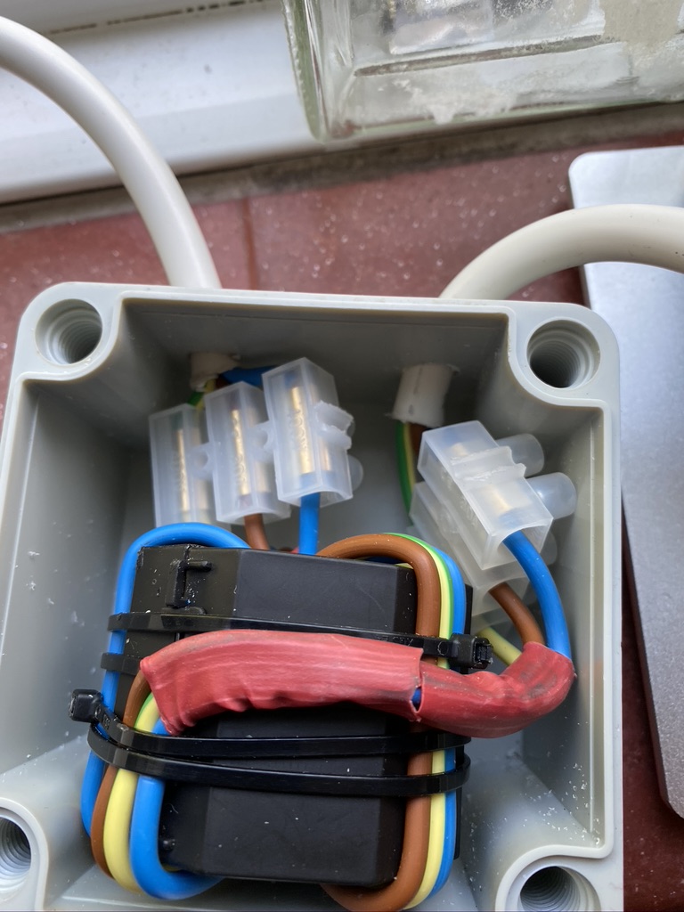
I started with stripping back some of the 3183Y Flex to bare out the live, netural and earth wires to wind around the ferrite. The heavy gauge of the wire made this quite a challenge, certianly being able to open the ferrite made a big different in creating a well fitting wire to the ferrite. I used cable ties to keep the ferrite and the wires stable.
The Terminal block comes in a massive pack, but its really good quality and will undoubtedly have many uses in the future, so worth having around. I attached these to the ferrite and wires, but not before attaching heatshrink to the wire going into the terminal. This not only looked good but kept the cable tidy.
I then set about measuring the thickness of the coax to make suitable sized holes into the box. I went in thru one side and so the mains feed and outward to the filter strip plug, nicely gapped so the terminal connectors in the box had a good seperation from them.
When drilling the holes I used a regular drill, but fettled the holes with a small round file to get the edges smooth and remove all the excess produced from the drilling.
The choke in its box – right side is the feed in, left side goes to the power strip with further mains filtering on.
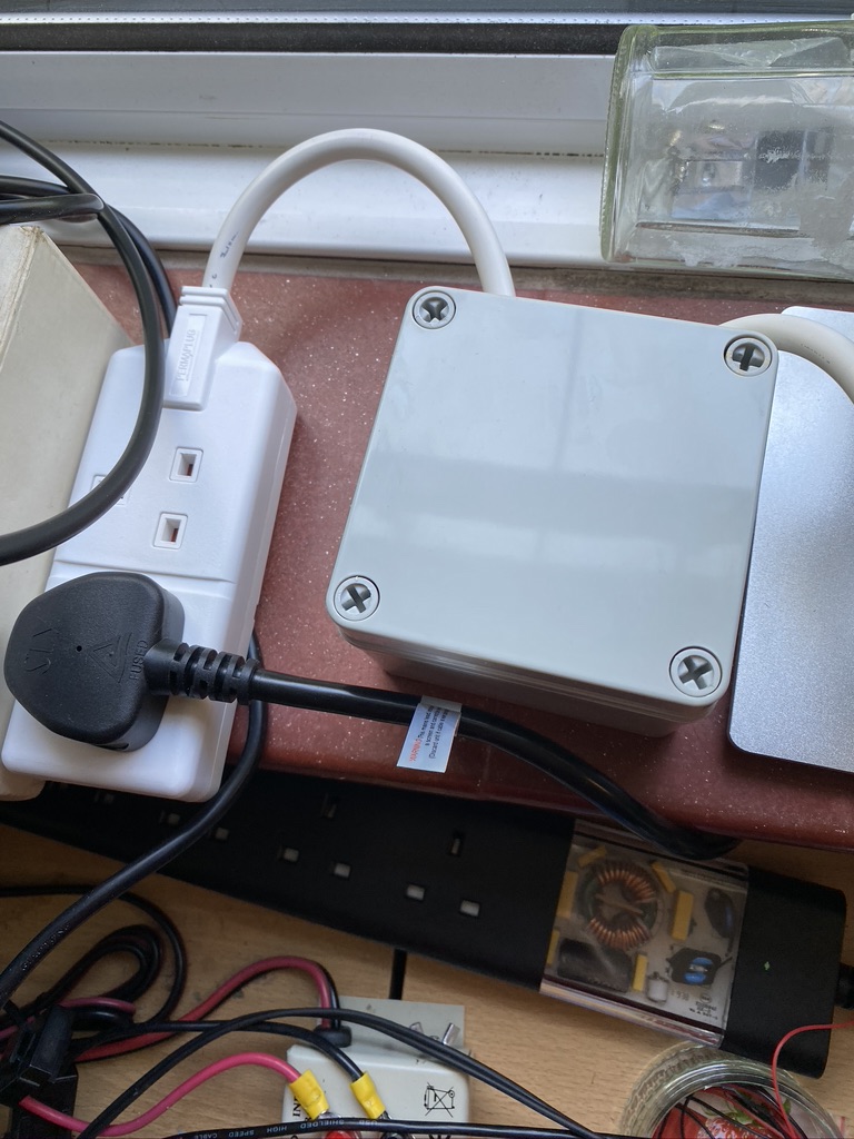
Before plugging into expensive radio equipment i tested on a B&Q light to ensure it would turn on and off/and light. (The lid is back on at this point) As this was my first time using this I kept one hand in my trouser(probably short) pockets, but the lights came on and no problems. I then set about putting it into the mains outlet and to connect the additonal filter
Mains filter after the RF filter which supplies the transformer
You will see the parts list contains 2 ferrites, the 2nd one went onto the back of the radio power supply feed directly
Ferrite on the input voltage to the transceiver
As this is 12V DC and whilst can give a nasty poke, a box isnt necessary here.
I went back to the LW frequencies that had previously been plauged by a ‘buzz’ that had now completely gone ! I went onto 80m and 40m and weak stations were getting thru and loud stations were BOOMING.
Whilst this was a fair amount of work, I’m satisfied it has helped reduce my QRM further.