So it has been a gorgeous sunny day with little to no rain down here in IO90BS today, of course it being a work day means that I am kept very busy ! However I do get a lunch break and made the absolute most of it !
The decision
So after yesterday was, i dont mind saying, hard work to get the mast up, I really pondered what my next steps are. The days are short, the weather, mostly wet & cold, doesnt lend itself to antenna building like those lovely long sunny days of being able to put an antenna and still have sunlight after it.
I watched Callums DX Commander piviot video, many, many times in the evening – and i thought, this has to be the way for me. On my own, getting an antenna up and down, i have to have as much help as I can get where engineering can give me that assistance. This was about 11:30 a night, and most of my sensible friends are asleep at that time, or at least wouldnt want to be disturbed on a Sunday night about ‘is it a good idea to build a mast tilt DIY’ so couldnt get a second opinon.
The build !
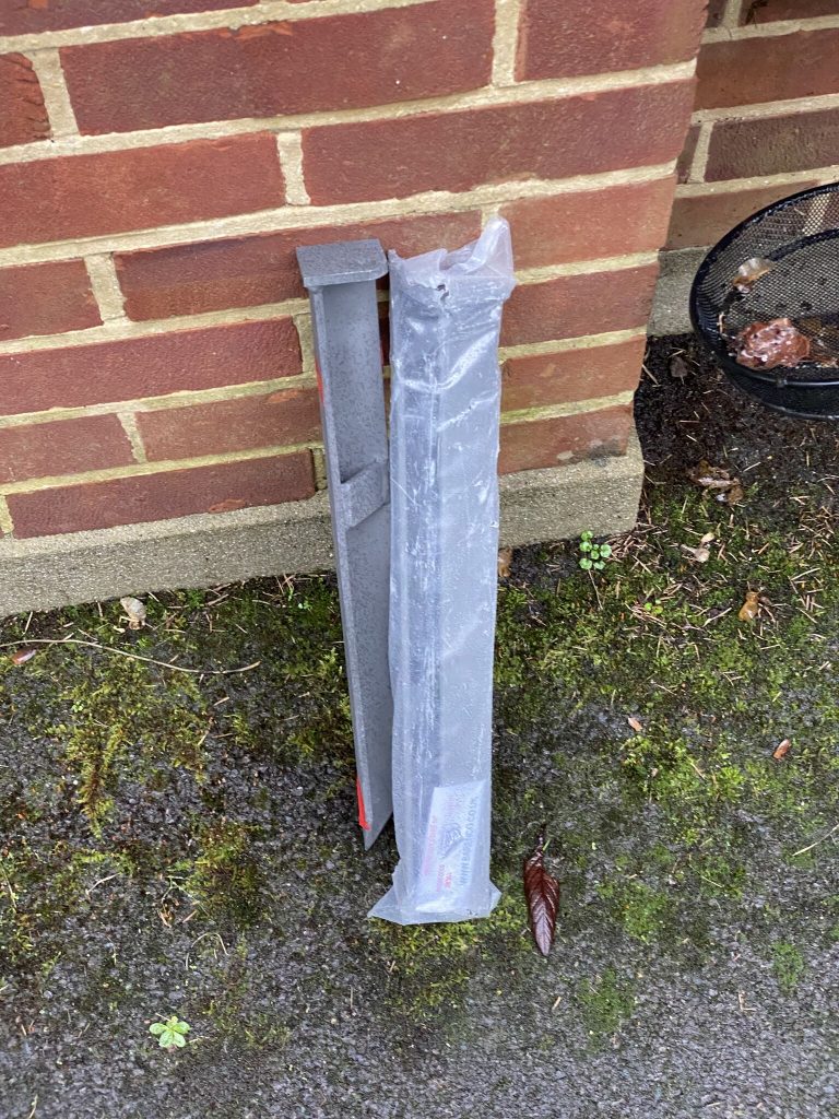
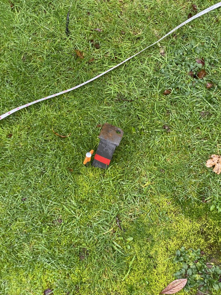
I asked my good friend, who we shall call ‘John the Brush’, some thoughts on the video. He is very capable and building and generally ‘making things work’. He was very quick to identify the required parts, which is something I couldn’t do after browsing B&Q and Wickes last night.
“he made that from a bit of M10 st4udding and some 100 x100mm fence post” – now i don’t know what M10 studding is, but B&Q sell it and it looks like the pole that Callum put thru the wood.
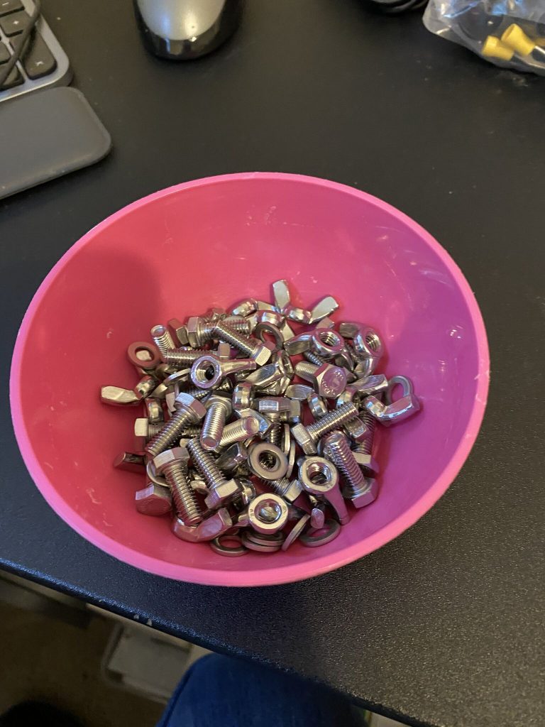
I’ve now ordered the wood (From Wickes) and the M10 and nuts and bolts from B&Q, total cost – £42.04 (including delivery). I have plenty of tools, although i have to say i love that Makita drill that Calum uses in his video – what an awesome bit of kit that is – i’ve got a Bosch SDS drill which i think should be able to do the same job.
So, that gives me a short-to-mid term plan for the Nebula, but what about NOW ! I dont like being off the air, it was hard work to get my lience and its a nice enjoyable, relaxing hobby (well putting 18m masts up can be a strain…)
The NOW
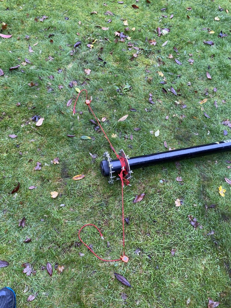
So I was pondering, what is the quickest antenna i can get up in the small window of time i have for lunch. I thought about and started getting the bits for the classic – i’ve got all the wires and can get it up and running pretty quick, but things can, and do go wrong.. Whilst i was untanglilng all the radials, i spotted my 40 meter dipole, and remembering Tim (G5TM) had just done a recent video on dipoles.
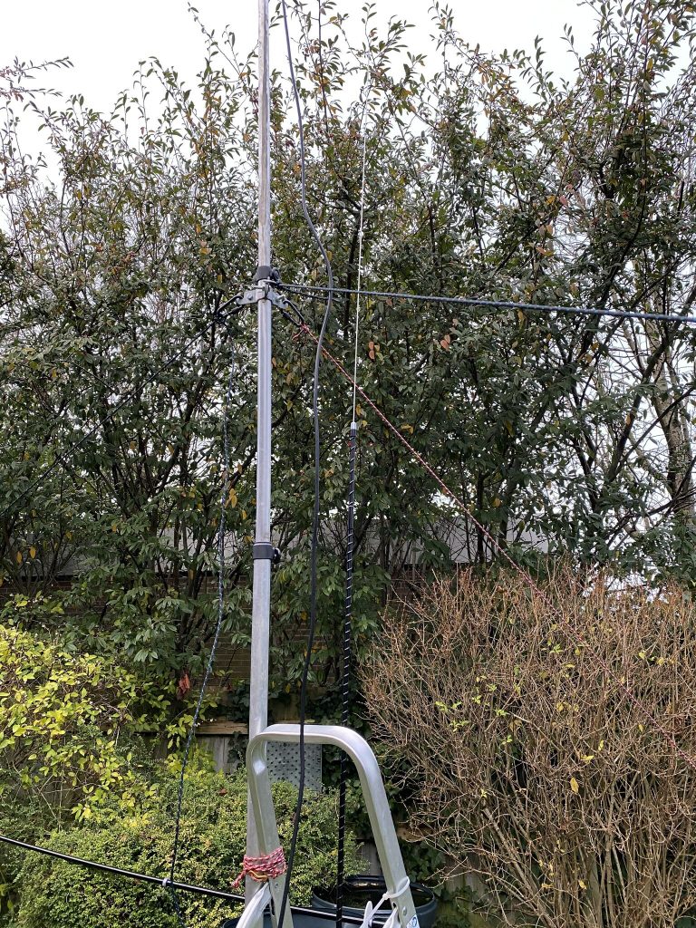
Dipole it is ! I had everything ready and could get this up pretty quick.
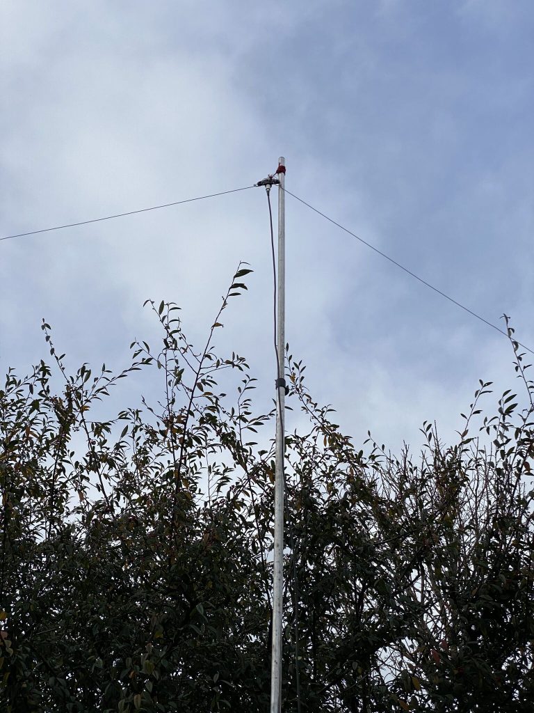
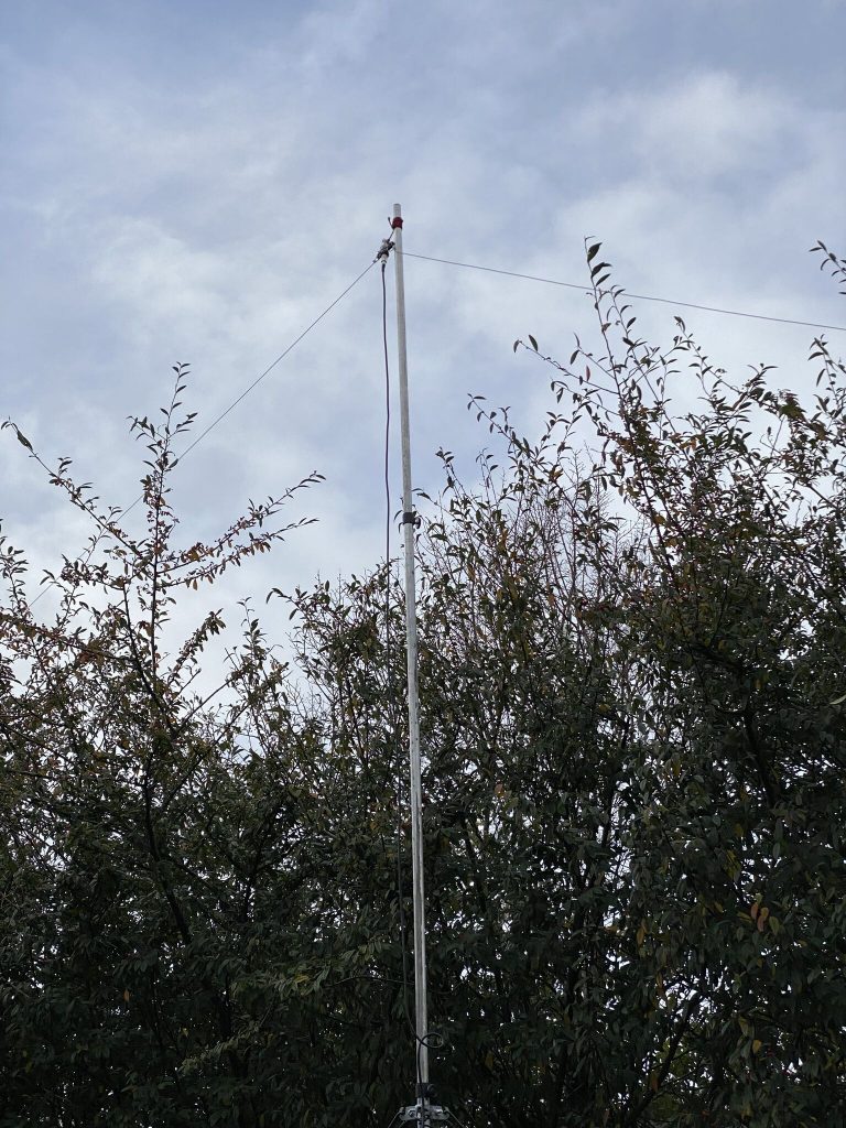
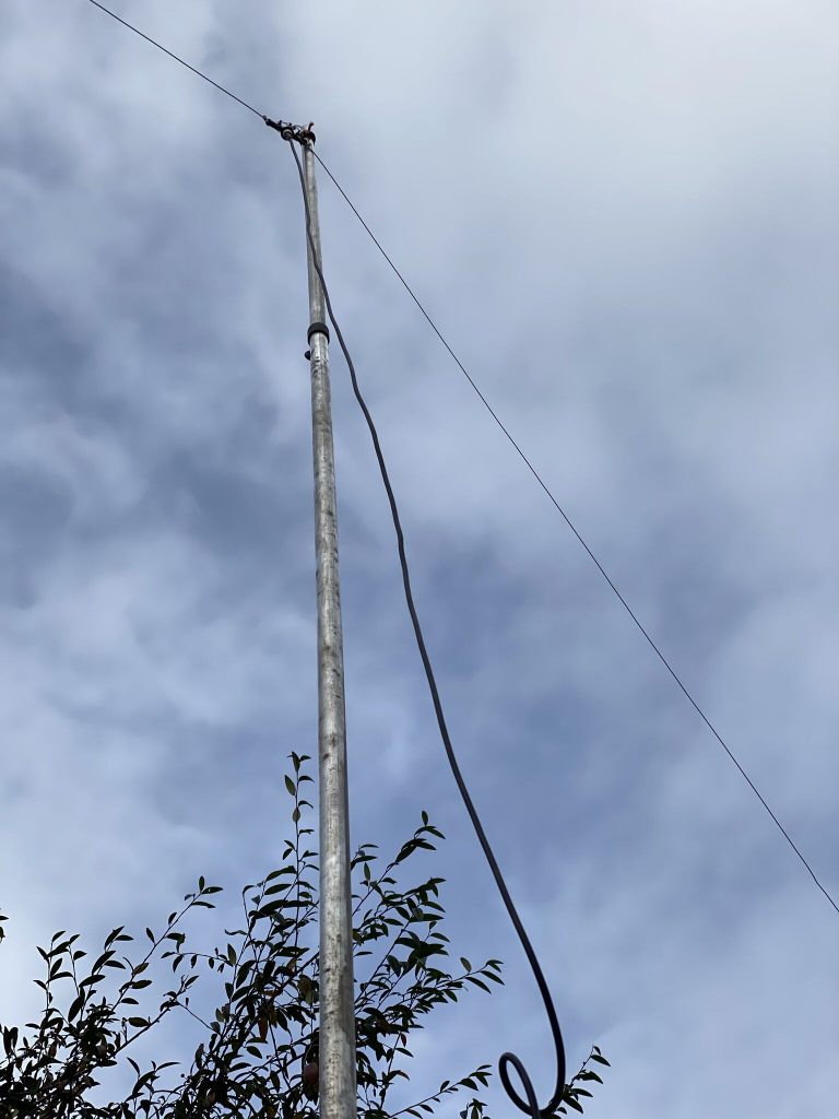
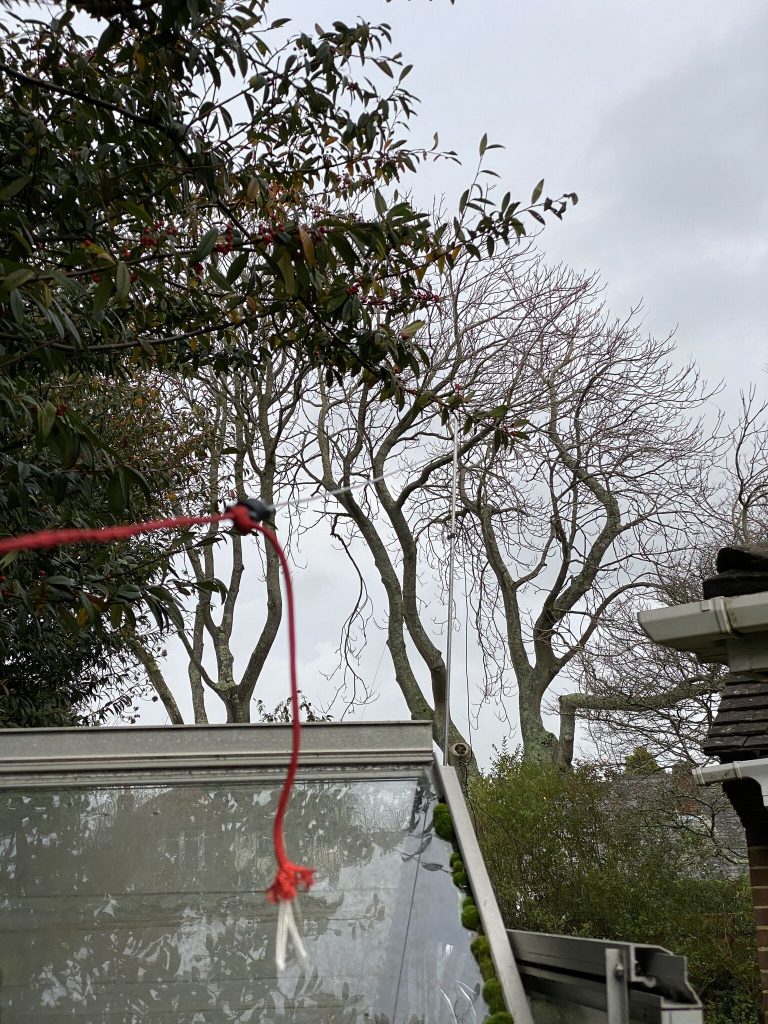
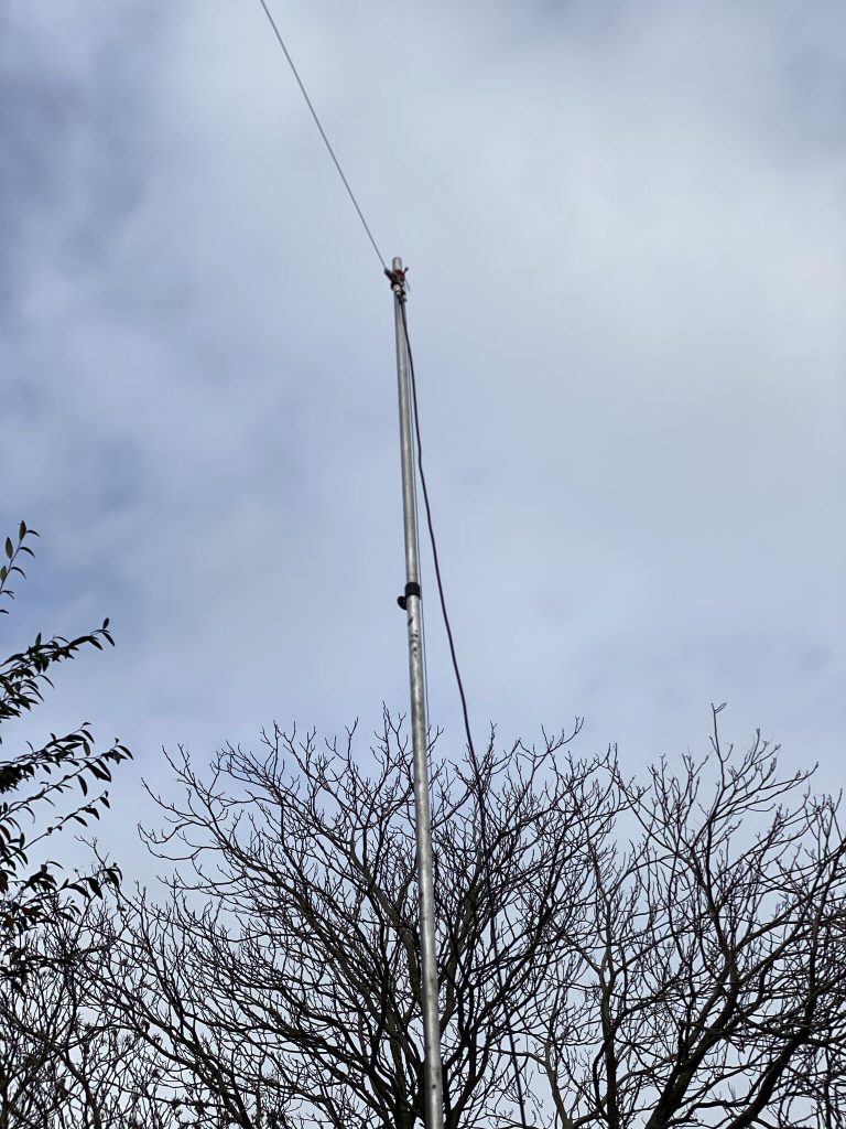
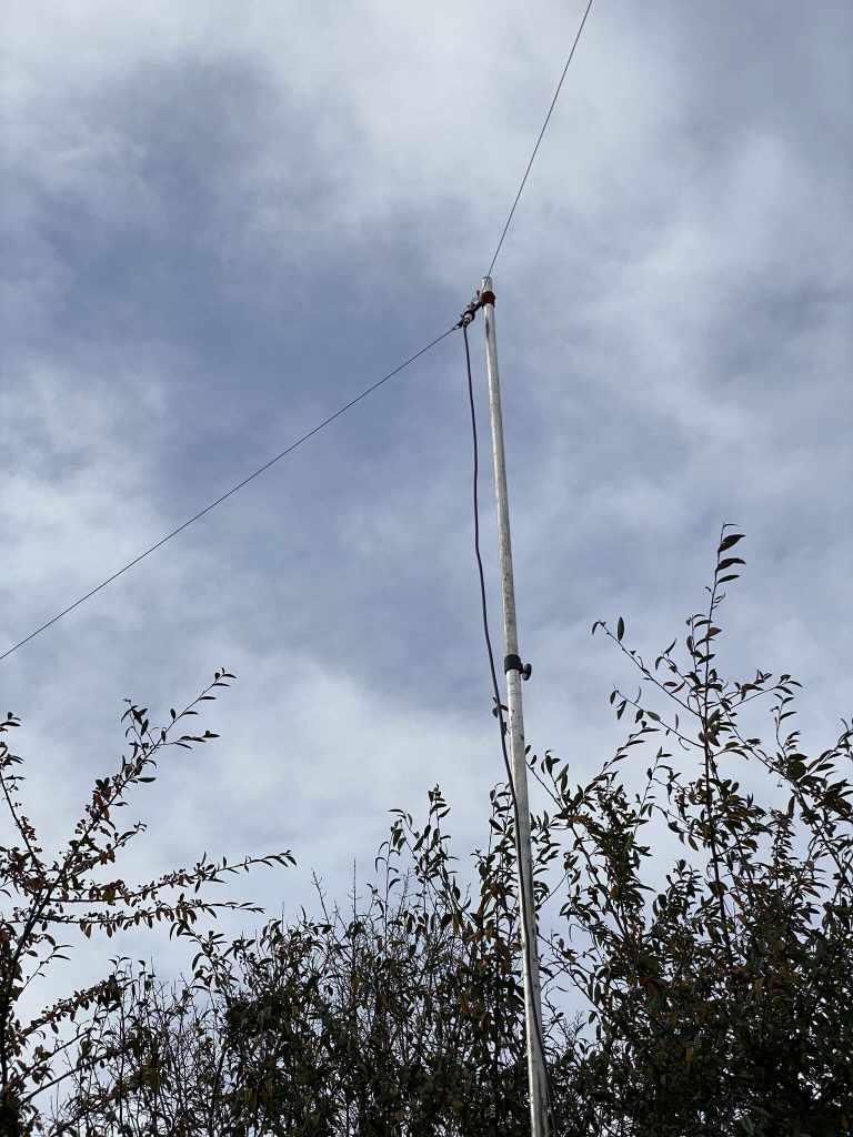
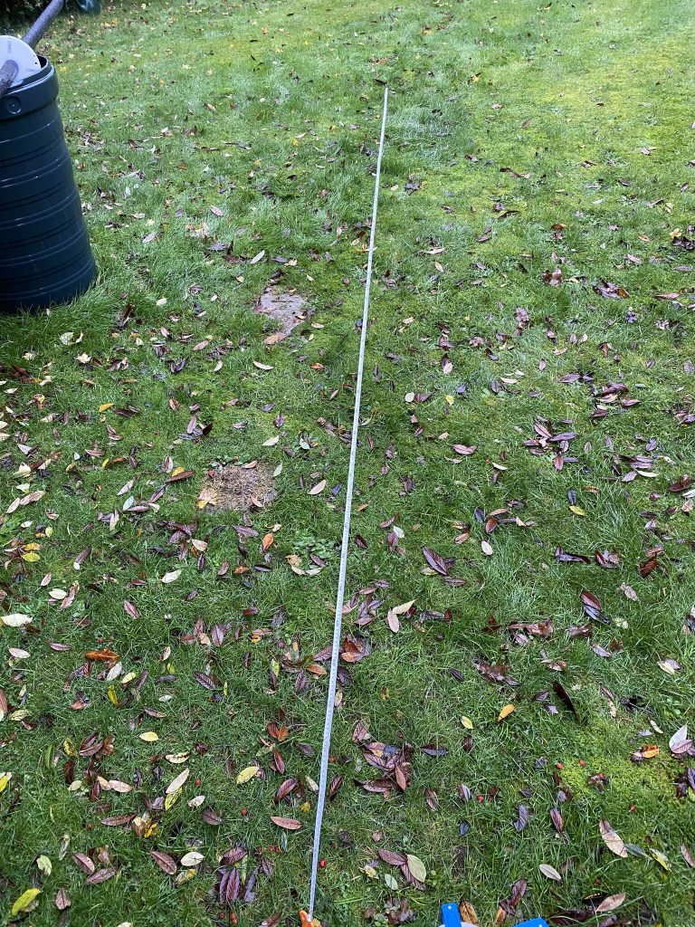
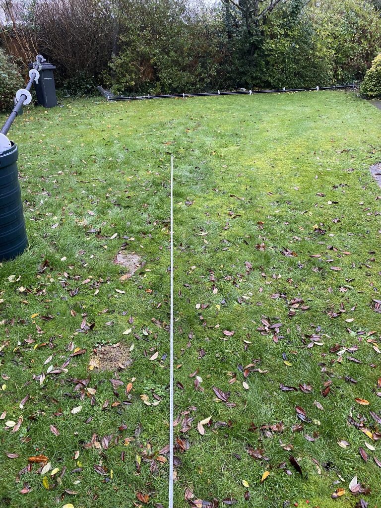
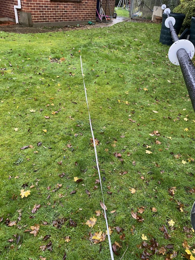
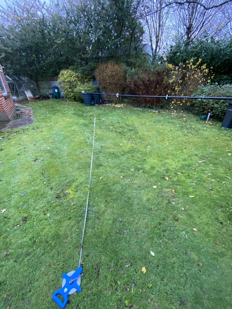
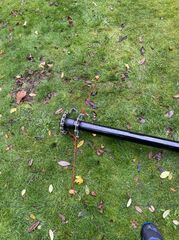
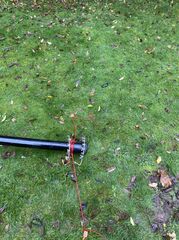
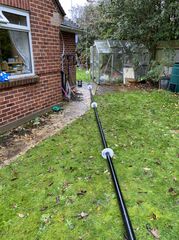
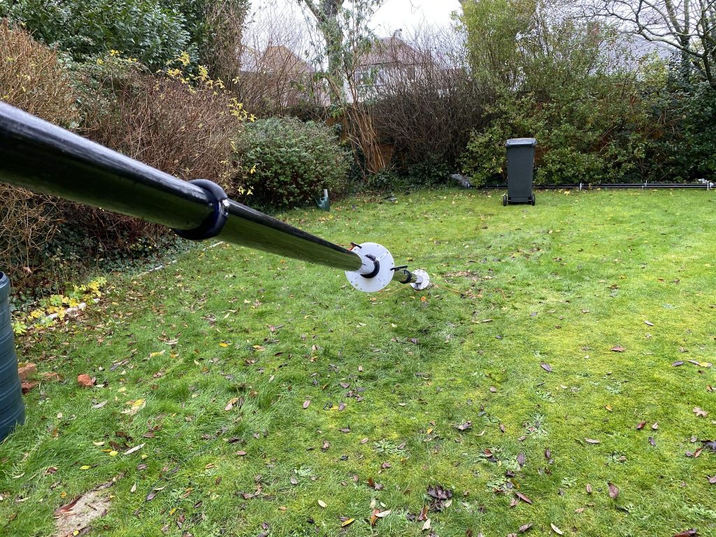
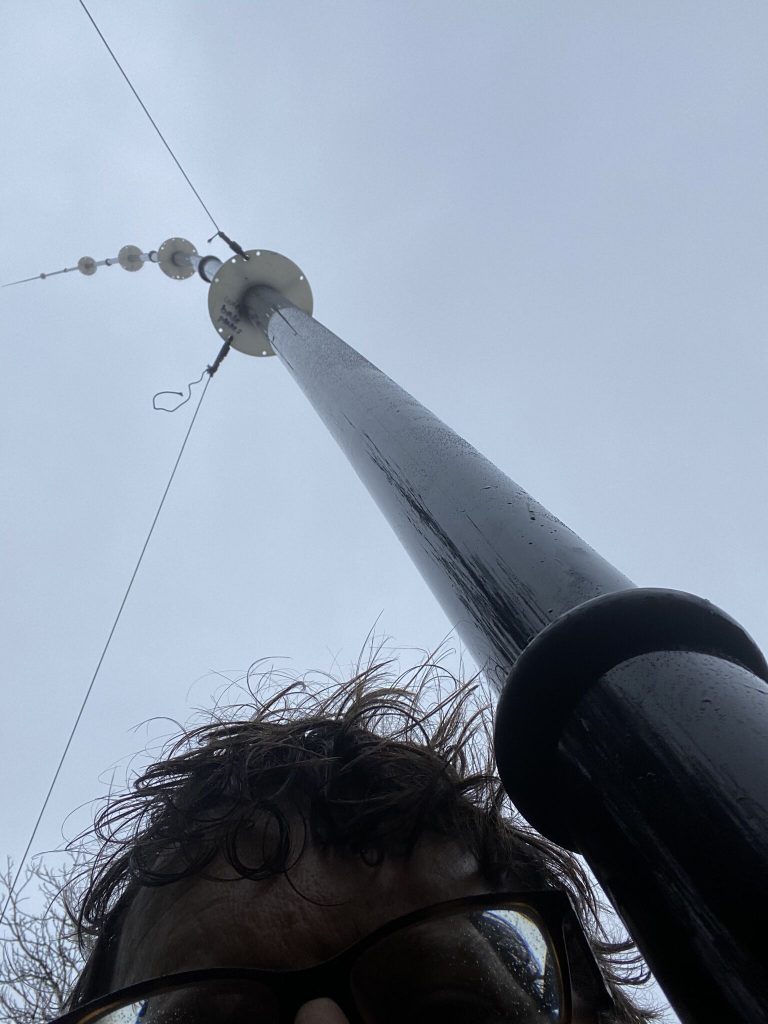
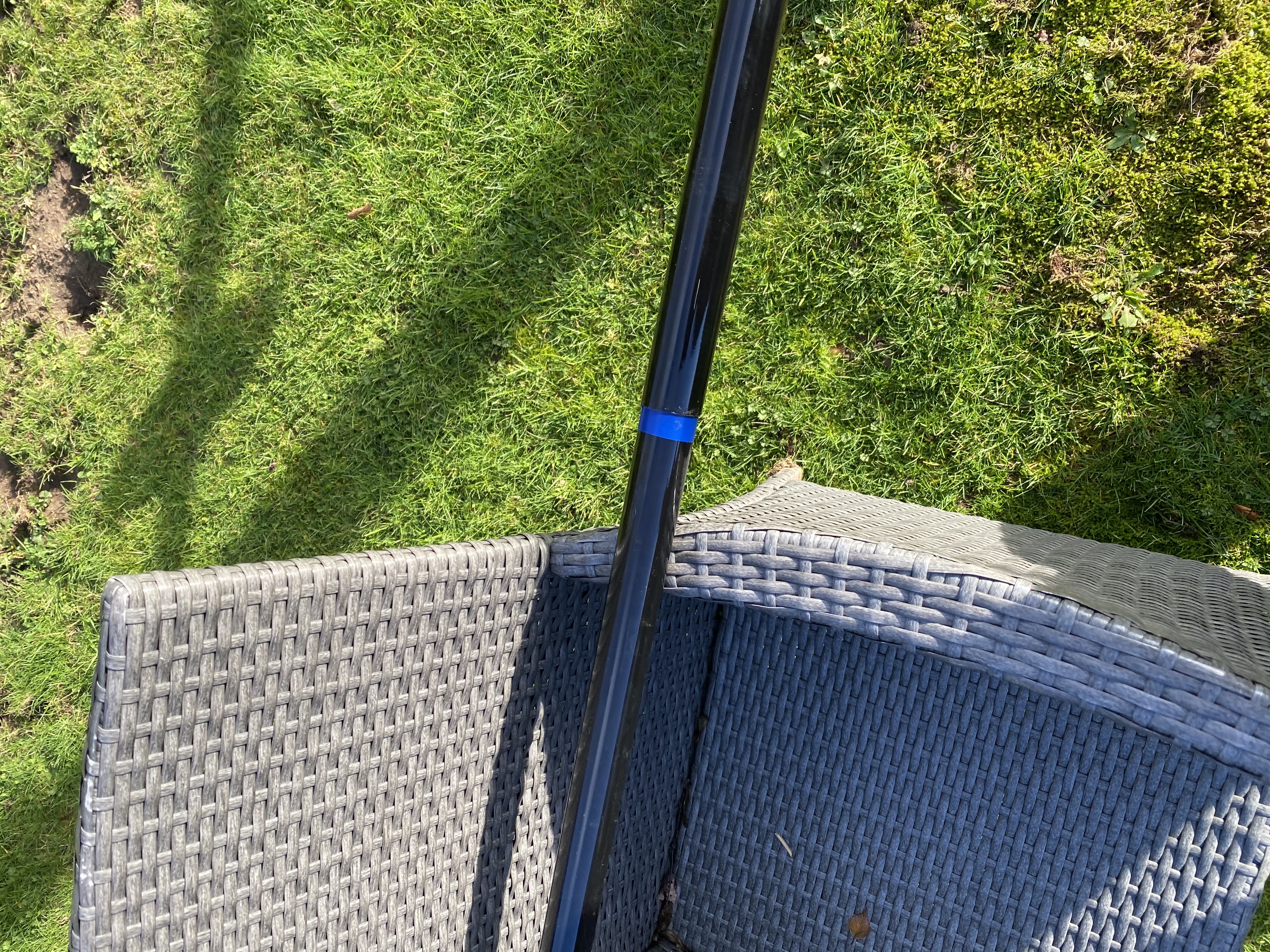
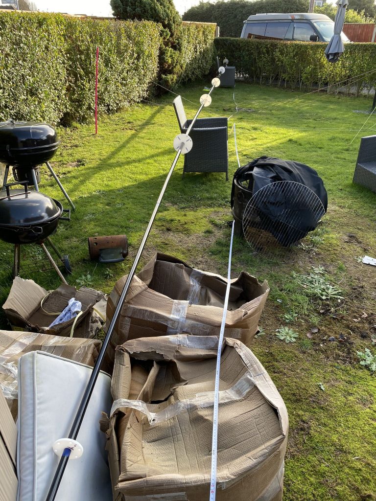
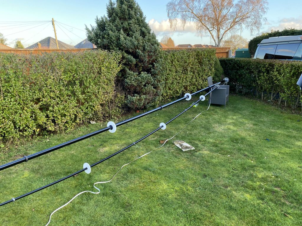
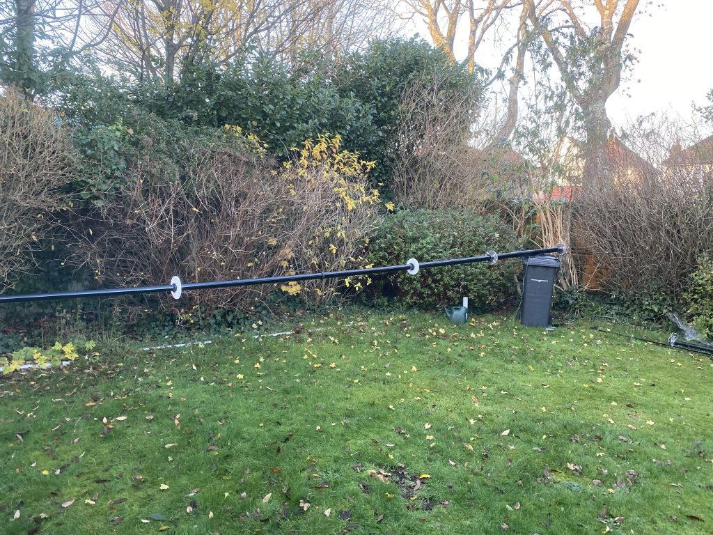
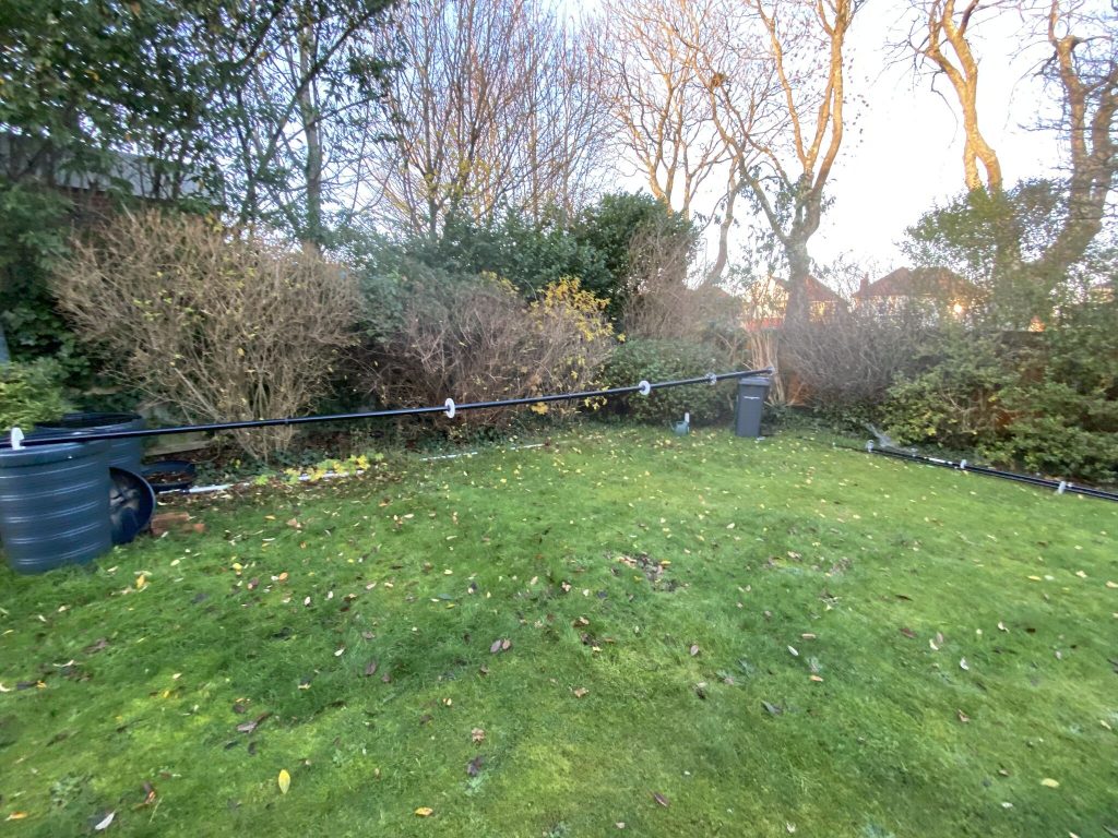
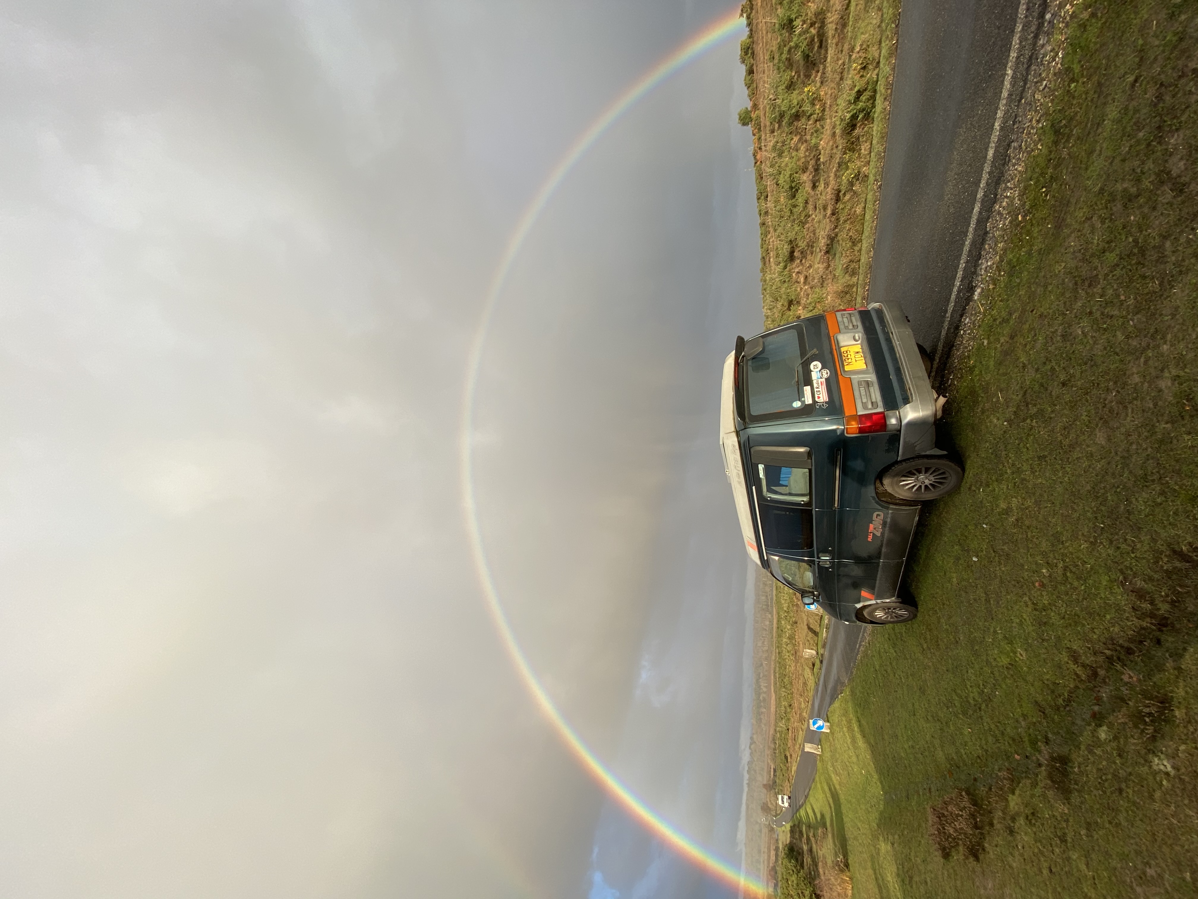
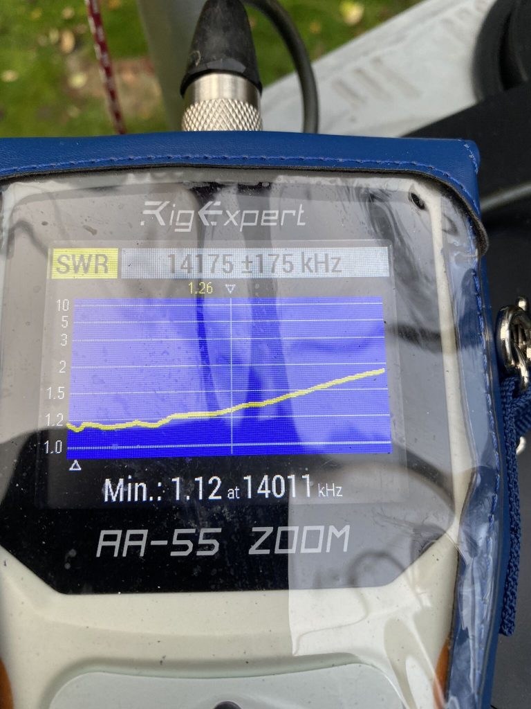
With one end attached to a washing line, another to fence post, it got my 40m antenna up in the air ! Now, time to see, how is the SWR..
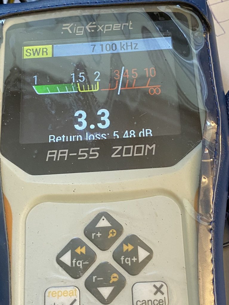
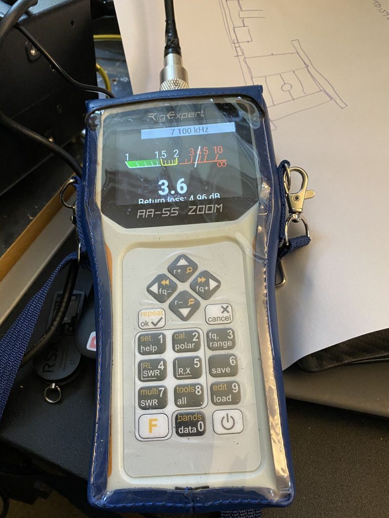
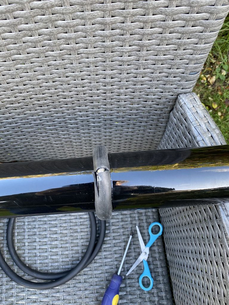
So i only had so much time, usually i’d be looking for between 1.5-2 on the SWR, but 3.3 was good enough – i did have to reposition the right-arm of the dipole as it was just touching the mast, that did get the SWR down a further .3 points.
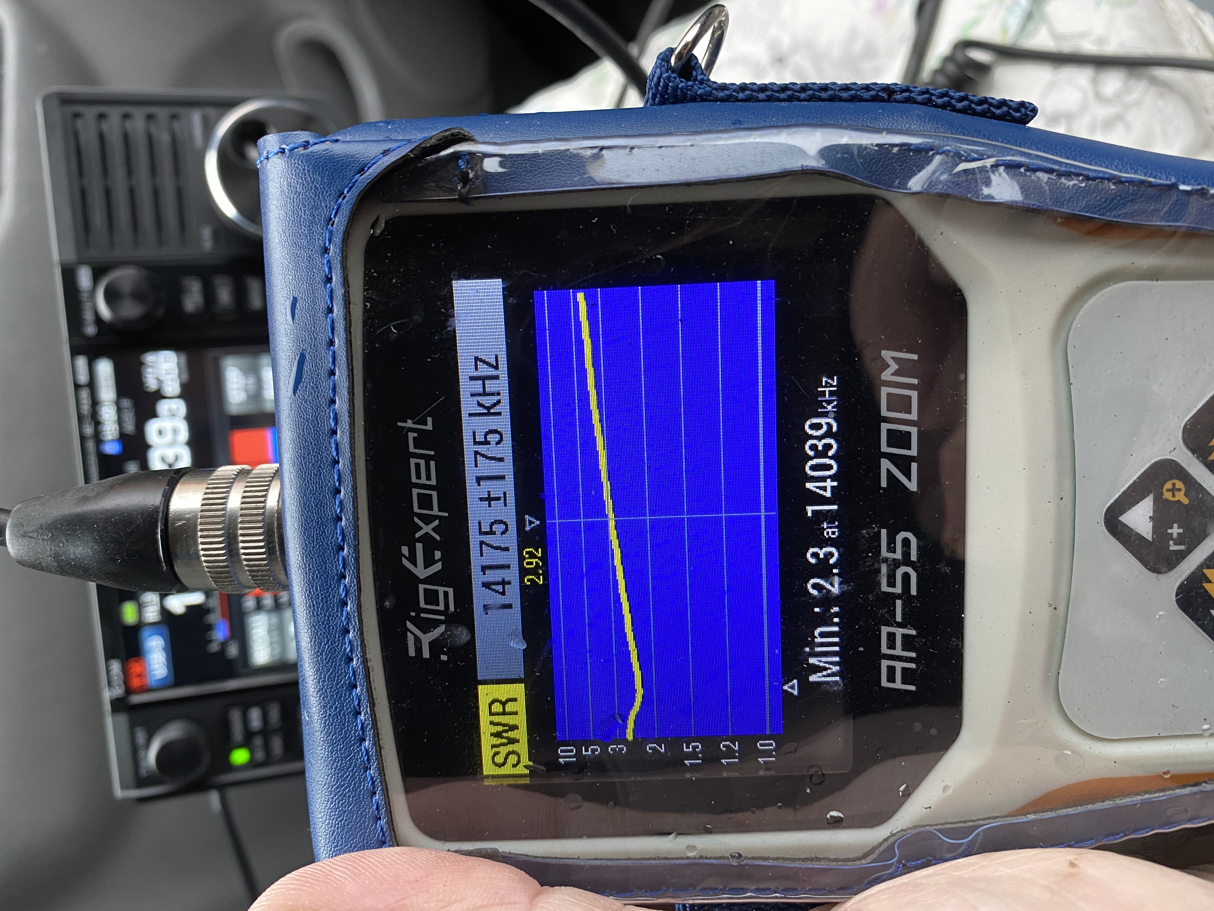
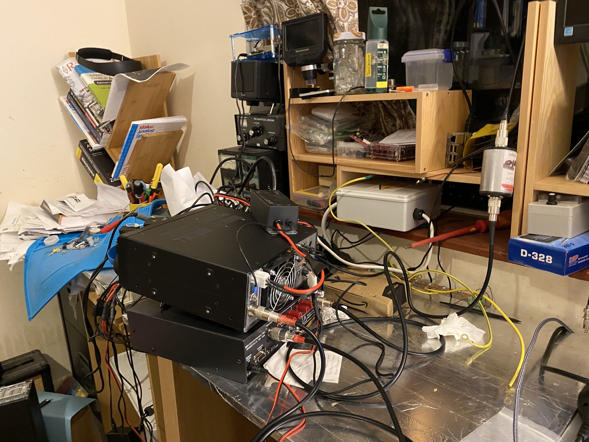
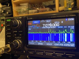
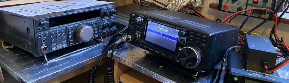
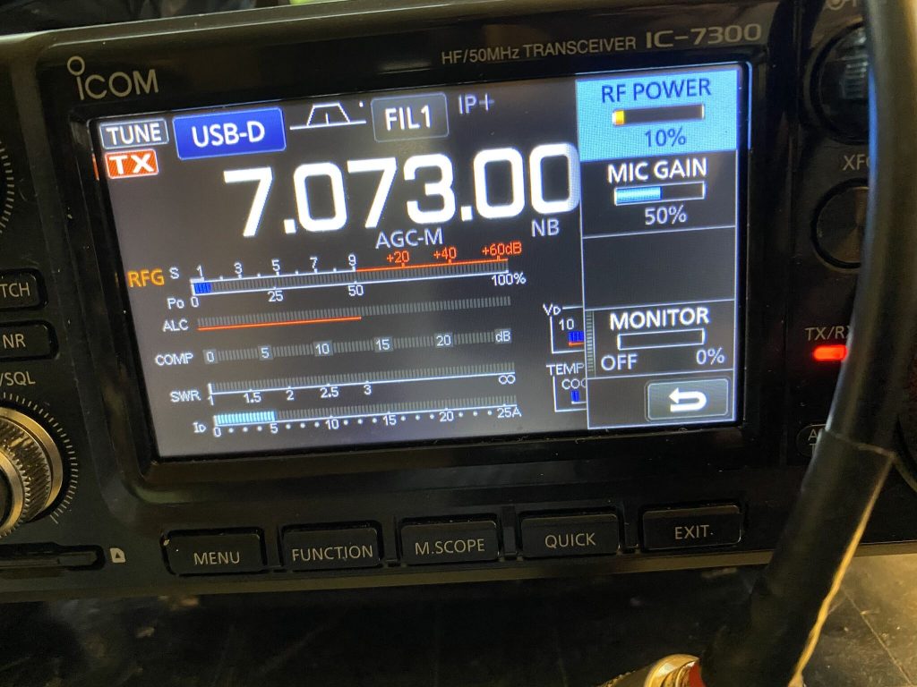
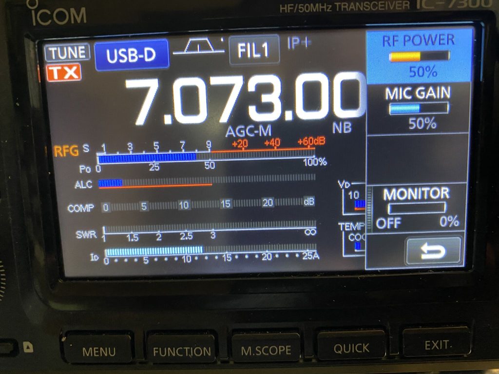
I went in and put it on the 7300, sure enough I could hit the ‘TUNE’ button and SWR was restored to 1:1 – this is on the 7300 internal tuner !
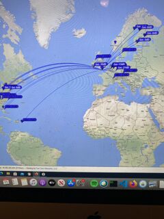
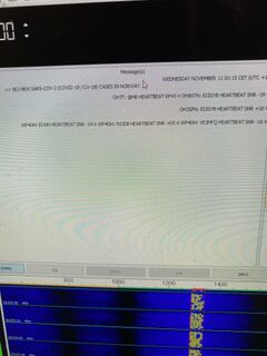
A quick test on FT8 yeilded positive results !
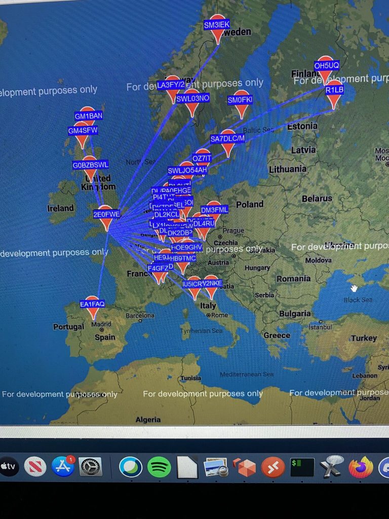
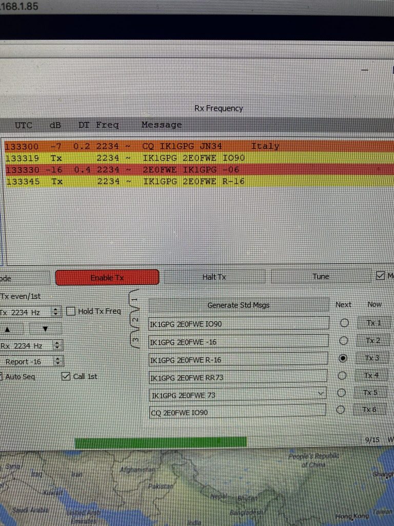
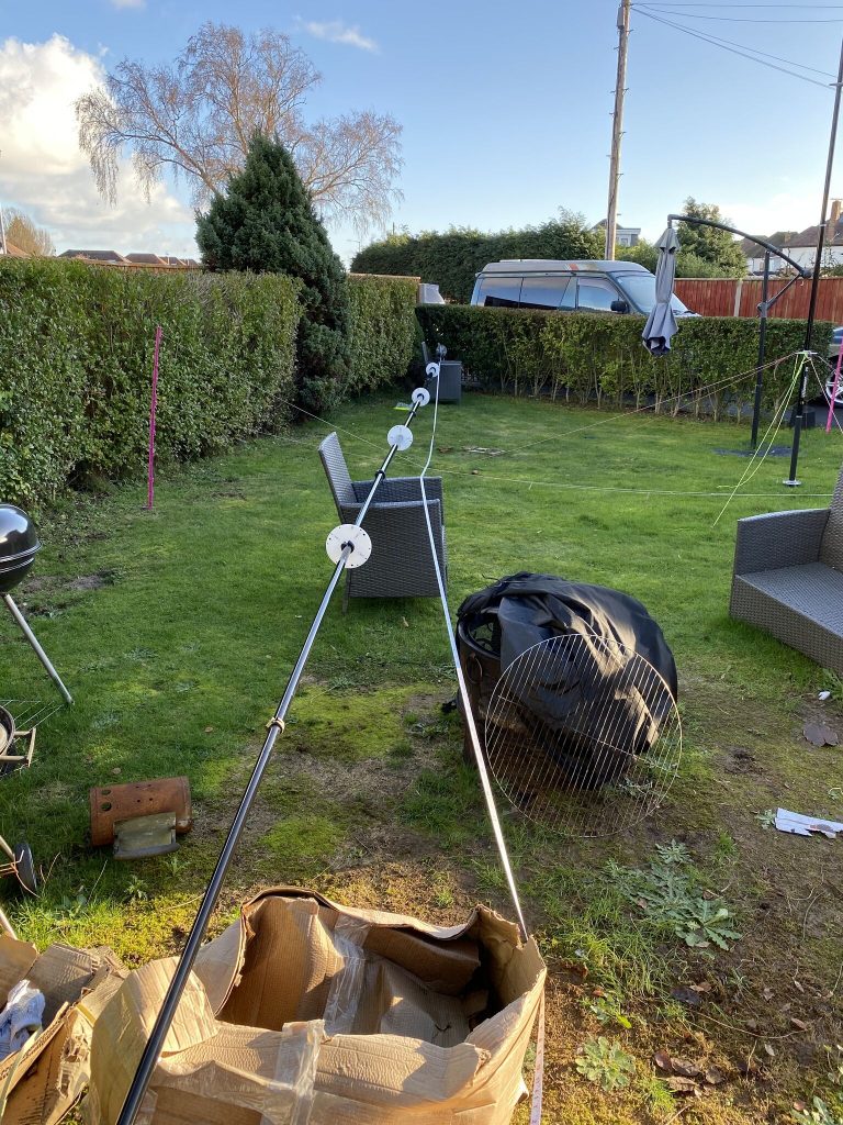
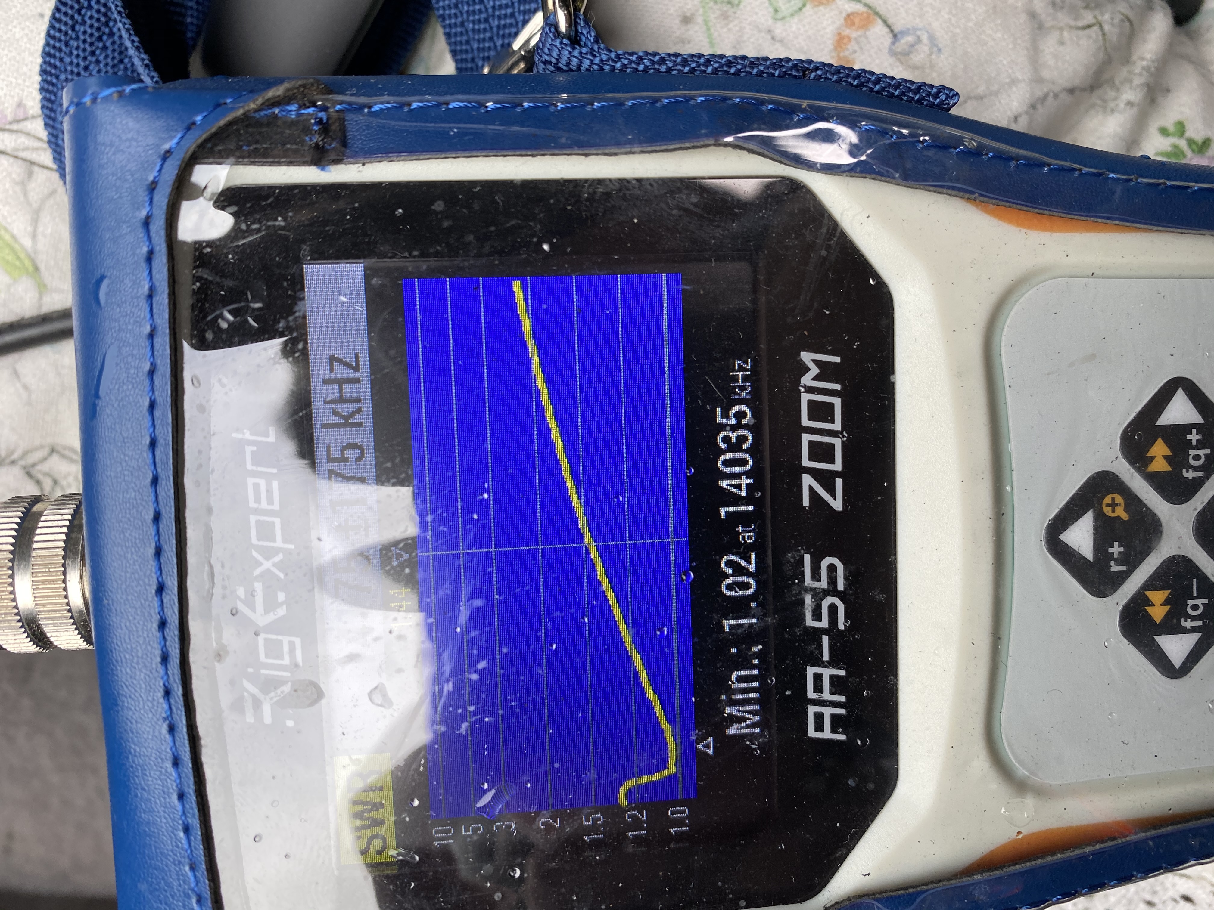
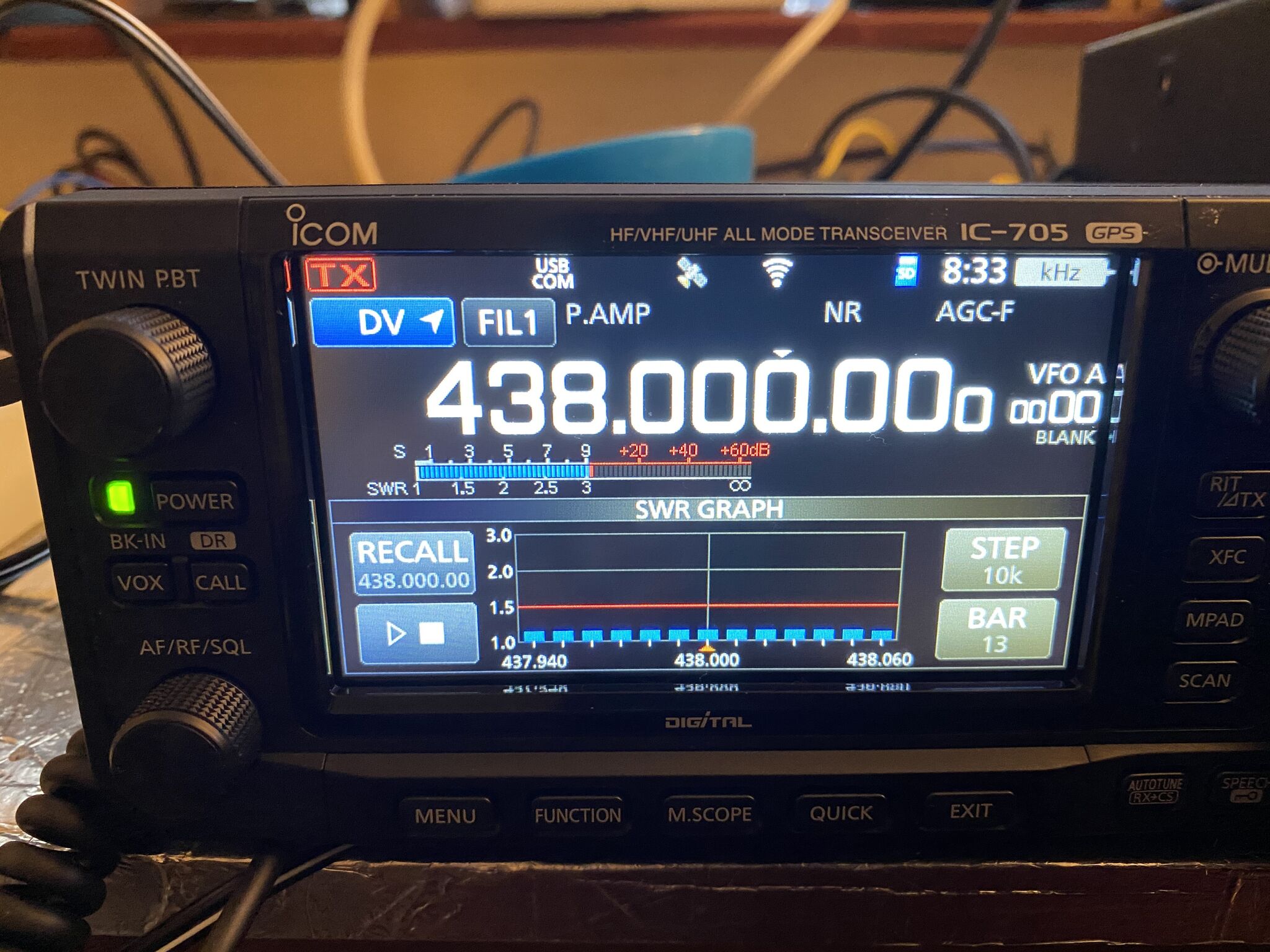
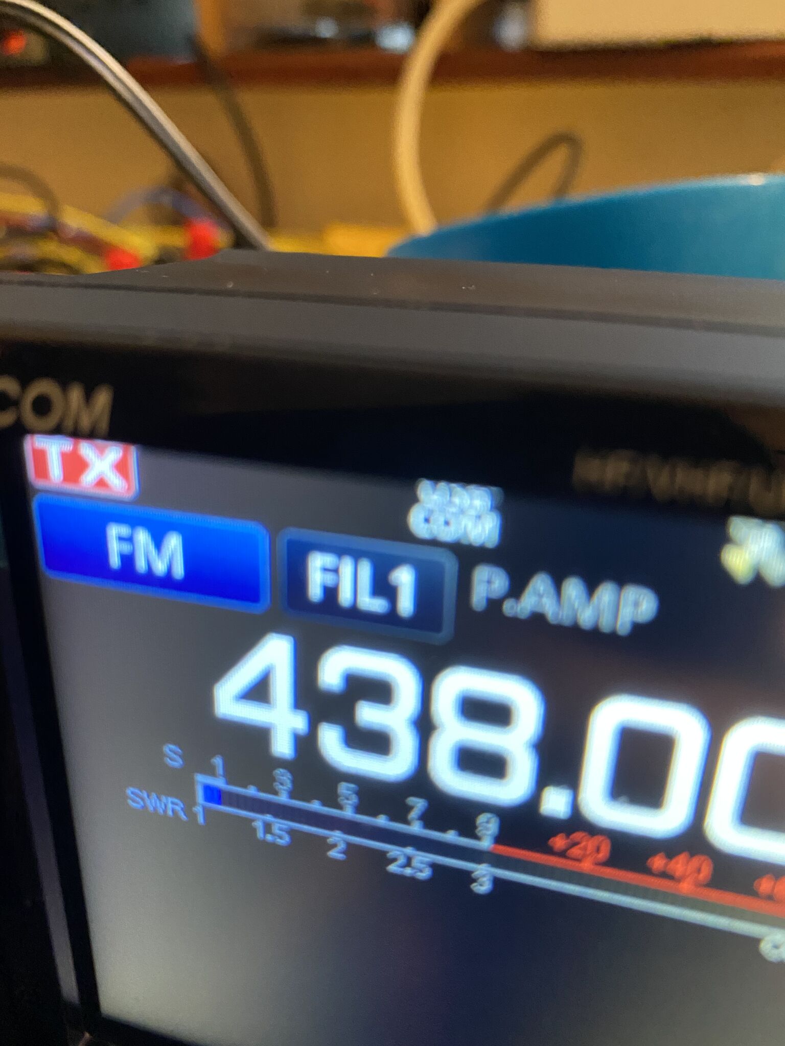
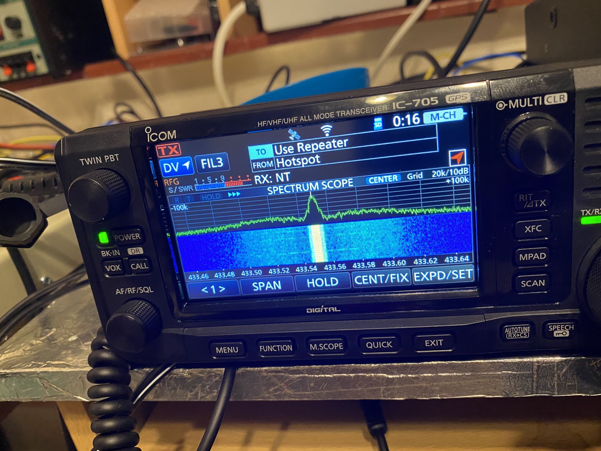
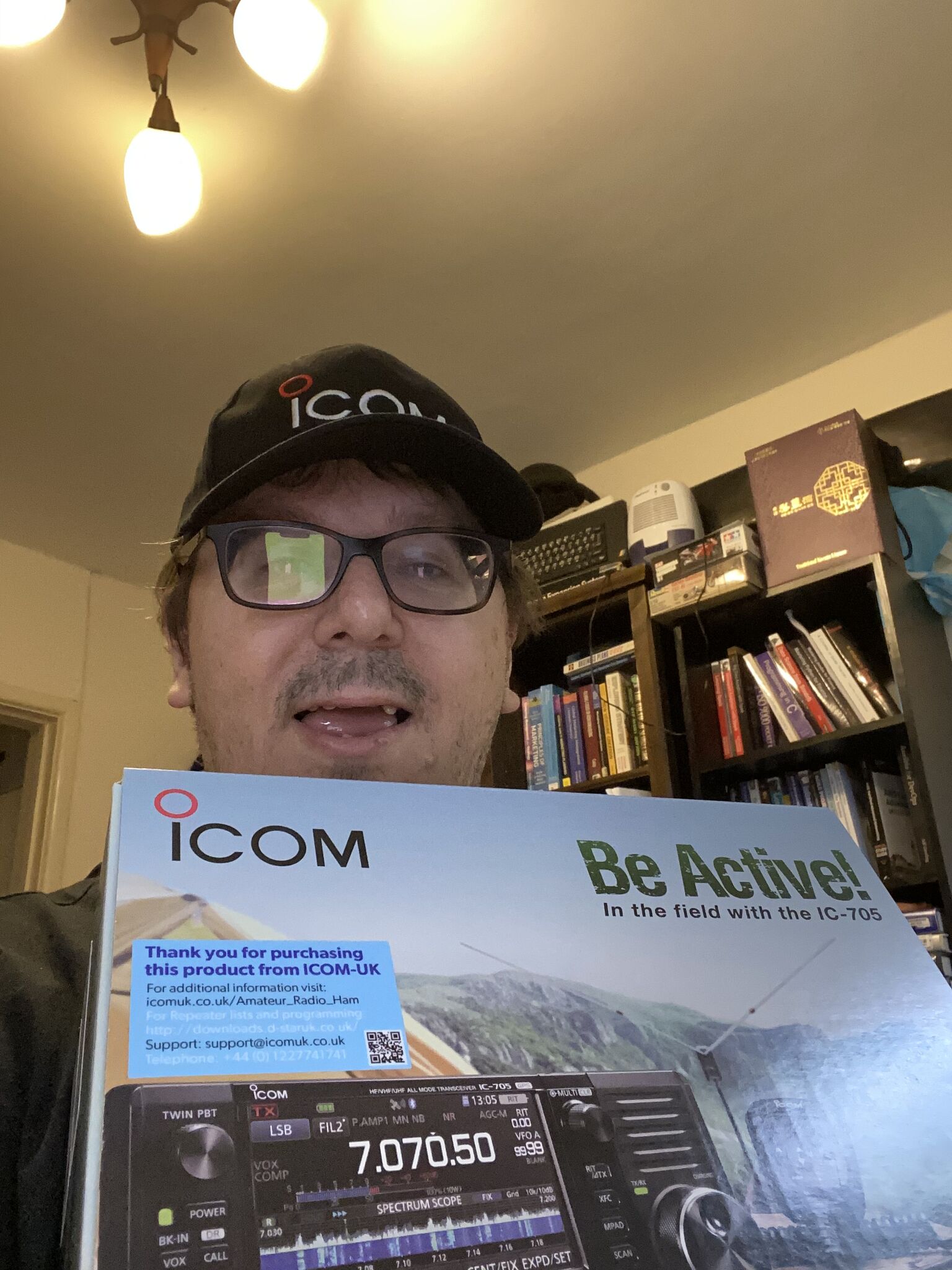
What a result, for less than an hours work, i was back on 40 meters. Then I eyeed the 705.. could i use that with 20m ‘whip’ on the mag mount ? hell, lets give it a try !
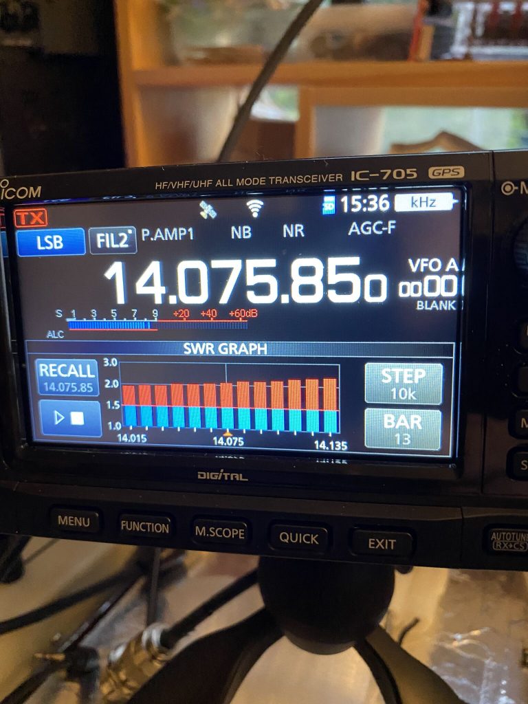
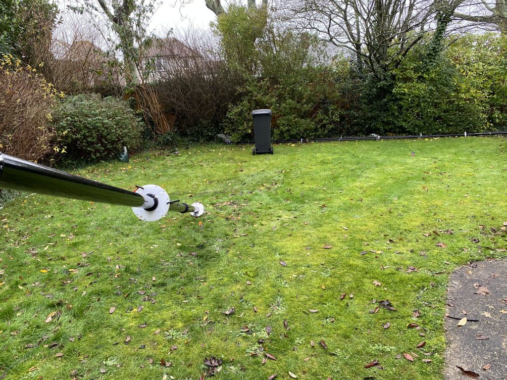
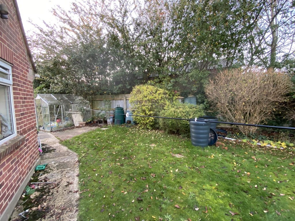
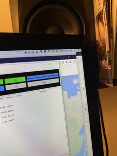
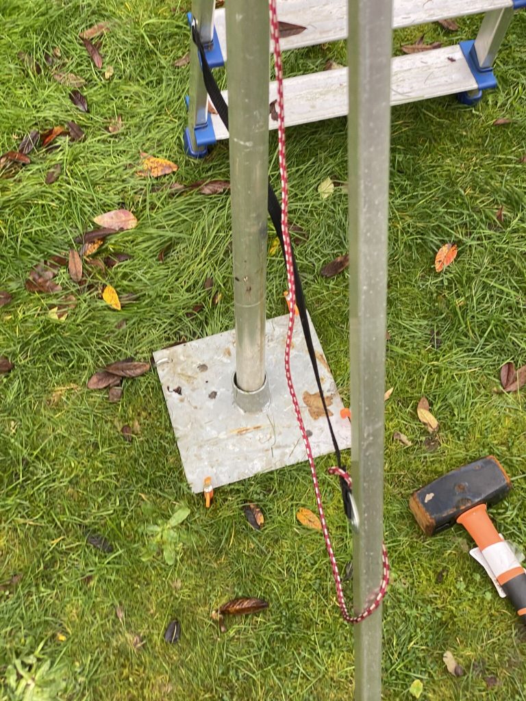
This really was ‘plug and play’ antenna, the mag-mount is on my step ladder, which gives some support (it is guyed as well) to my dipole mast. The SWR results on the 705 were slightly higher than the Rig Expert, but still not bad for such a quick, and somewhat crazy, setup.
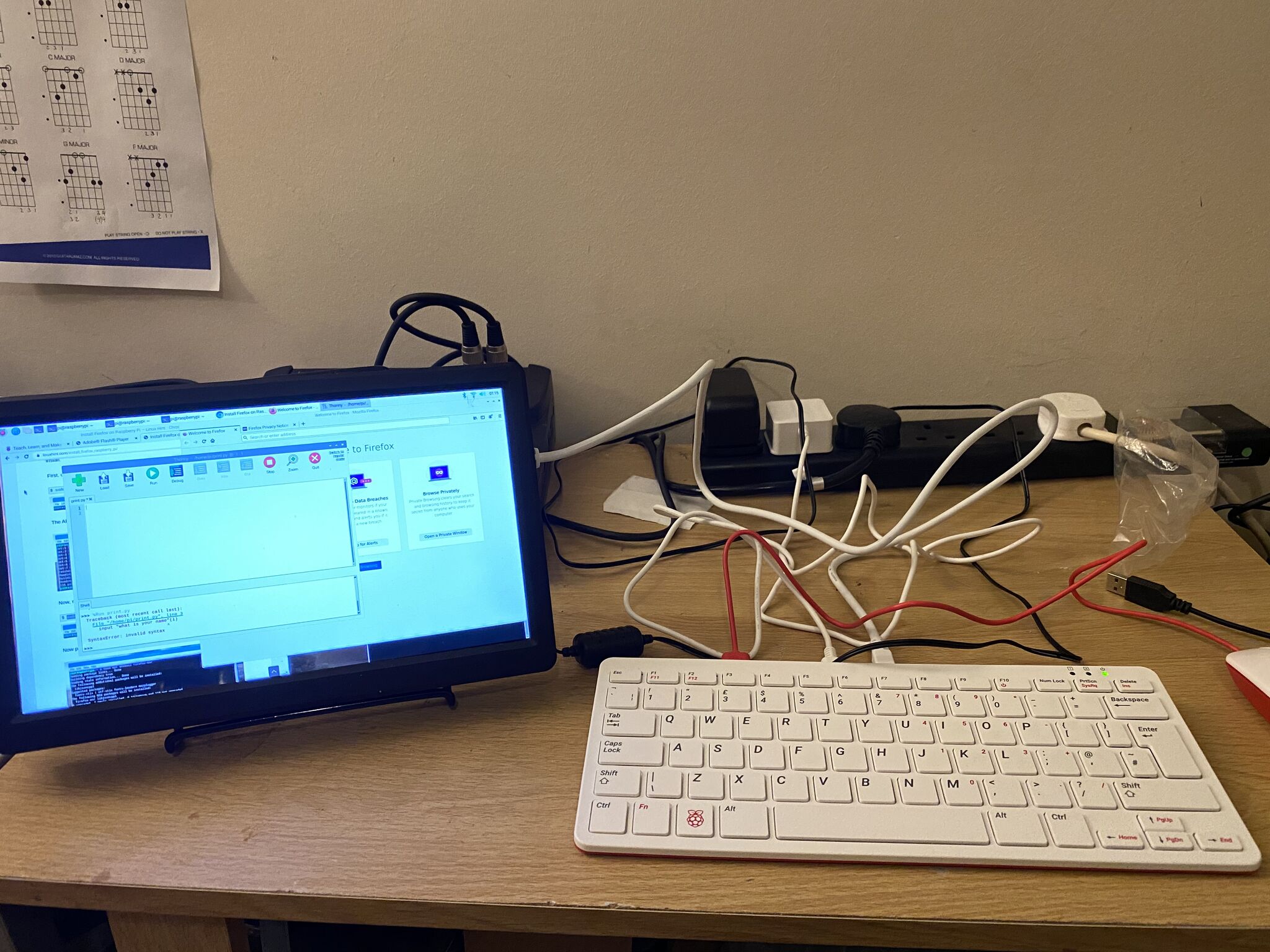
I was able to tune FT8 audiably, but have nothing to receive. Next project – Raspberry Pi 400 on the IC705 !
Conclusion
So I’m back on air, able to enjoy listening and transmitting on 40m and potenitally 20m as well , as well as a fix in plan to get the Nebula up. I’m really happy that i can quickly get back on line and also progress the Nebula.
Hopefully tomorrow I will be able to test 20m in the day, even WSPR would be amazing, at a push FT8 ? (FT8 requires working/engaging with the app, I’m working in the day).
Big thanks to “John the Brush” (who is a ham, but doesnt go on air!), Tim and of course Callum !